¶ Touch Sensor Module
¶ Overview
In this experiment, we will learn how to use the metal touch module.
¶ Touch sensor module
Touch sensitive switch. Touching the sensor pin produces an output at the ‘DO’ pin. The output is not a clean signal but includes 50 Hz mains induced signals (‘mains hum’). The output signal is ‘active high’ and the circuit sensitivity can be adjusted with a pot. An analog output signal from the sensor is available at pin ‘AO’.
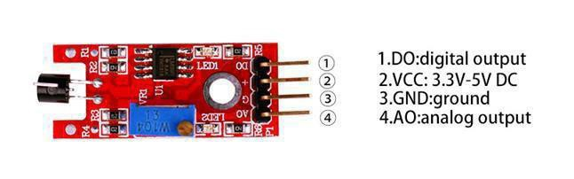
This sensor can output both analog and digital signals simultaneously. In most application scenarios, only the digital signal is used to realize switching functions. It outputs a high level when the built-in metal probe of the sensor is physically touched, and a low level when the probe remains untouched.
¶ Connection Schematic
¶ Wiringdiagram
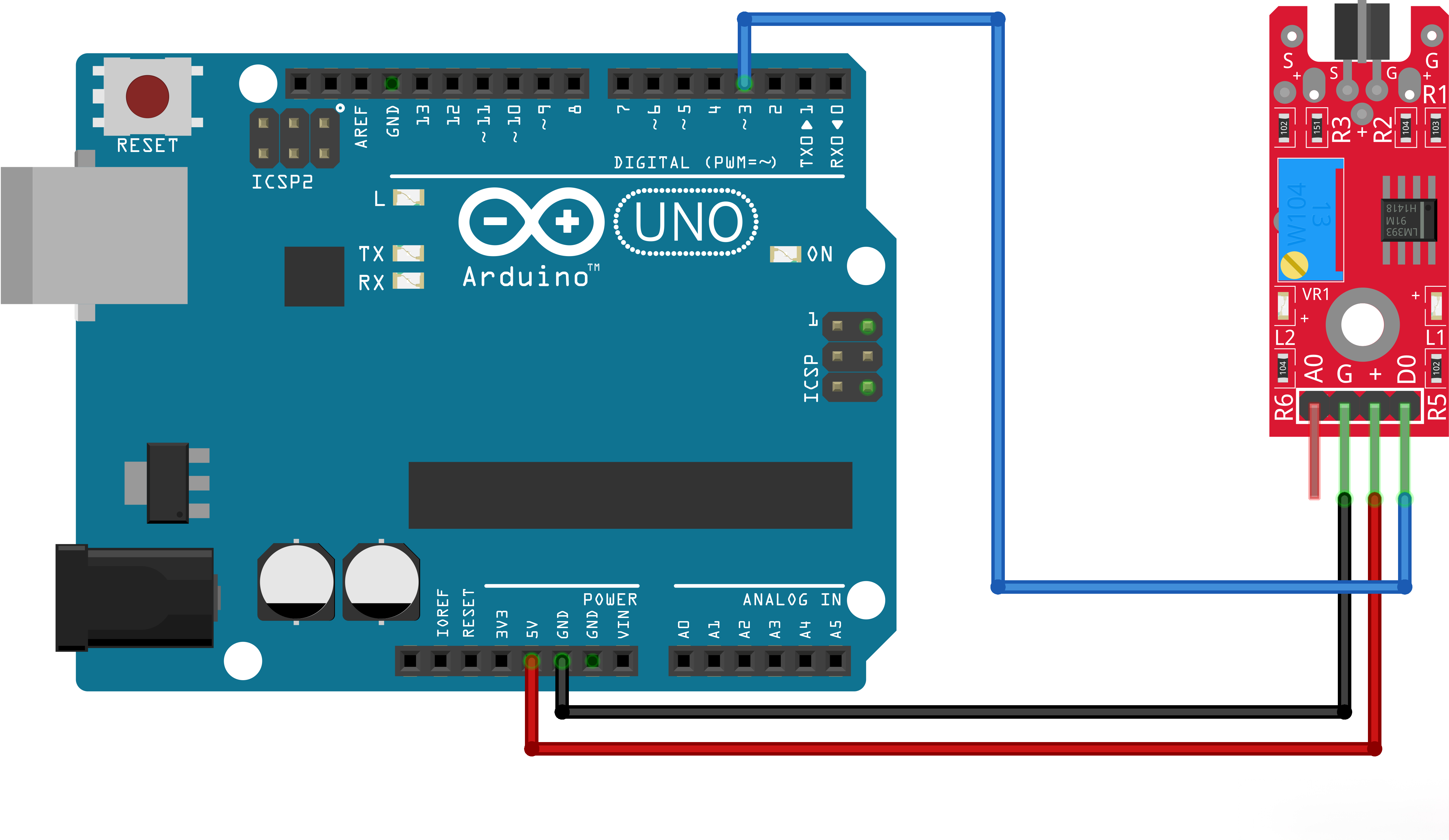
¶ Code
You can click the blue text link to download the program file to your local device, and double-click the file to open it after the download is complete. Please note: Before opening the file, ensure that you have installed the Arduino IDE development environment and completed the installation of relevant components such as the board support package and driver corresponding to the board.
int Led=5; //define LED port
int buttonpin=18; //define switch port;
int val; //define digital variable valvoid setup()
{
pinMode(Led,OUTPUT);//define LED as a output port
pinMode(buttonpin,INPUT);//define switch as a output port
}
void loop(){ val=digitalRead(buttonpin);//read the value of the digital interface 3 assigned to val
if(val==HIGH)//when the switch sensor have signal, LED blink
{
digitalWrite(Led,HIGH);
}
else
{
digitalWrite(Led,LOW);
}
}
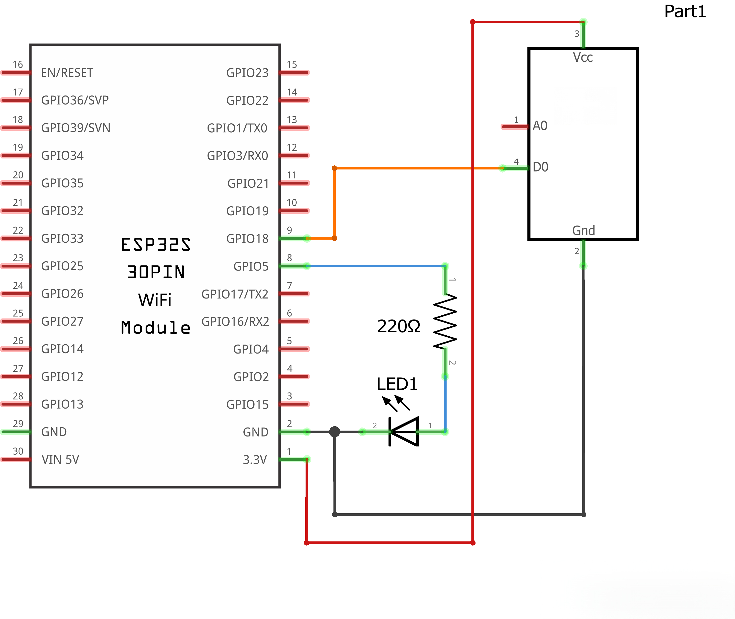
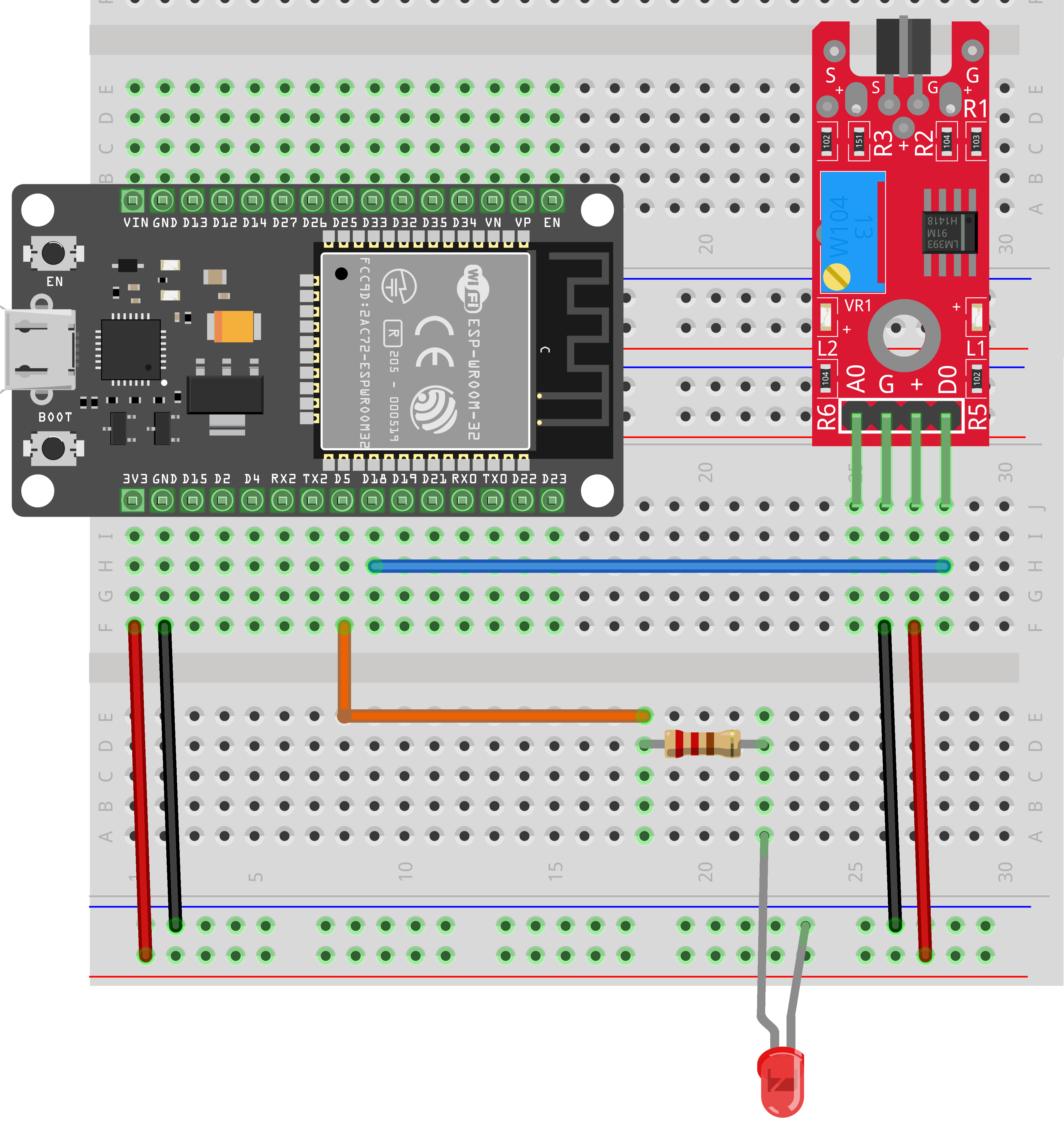
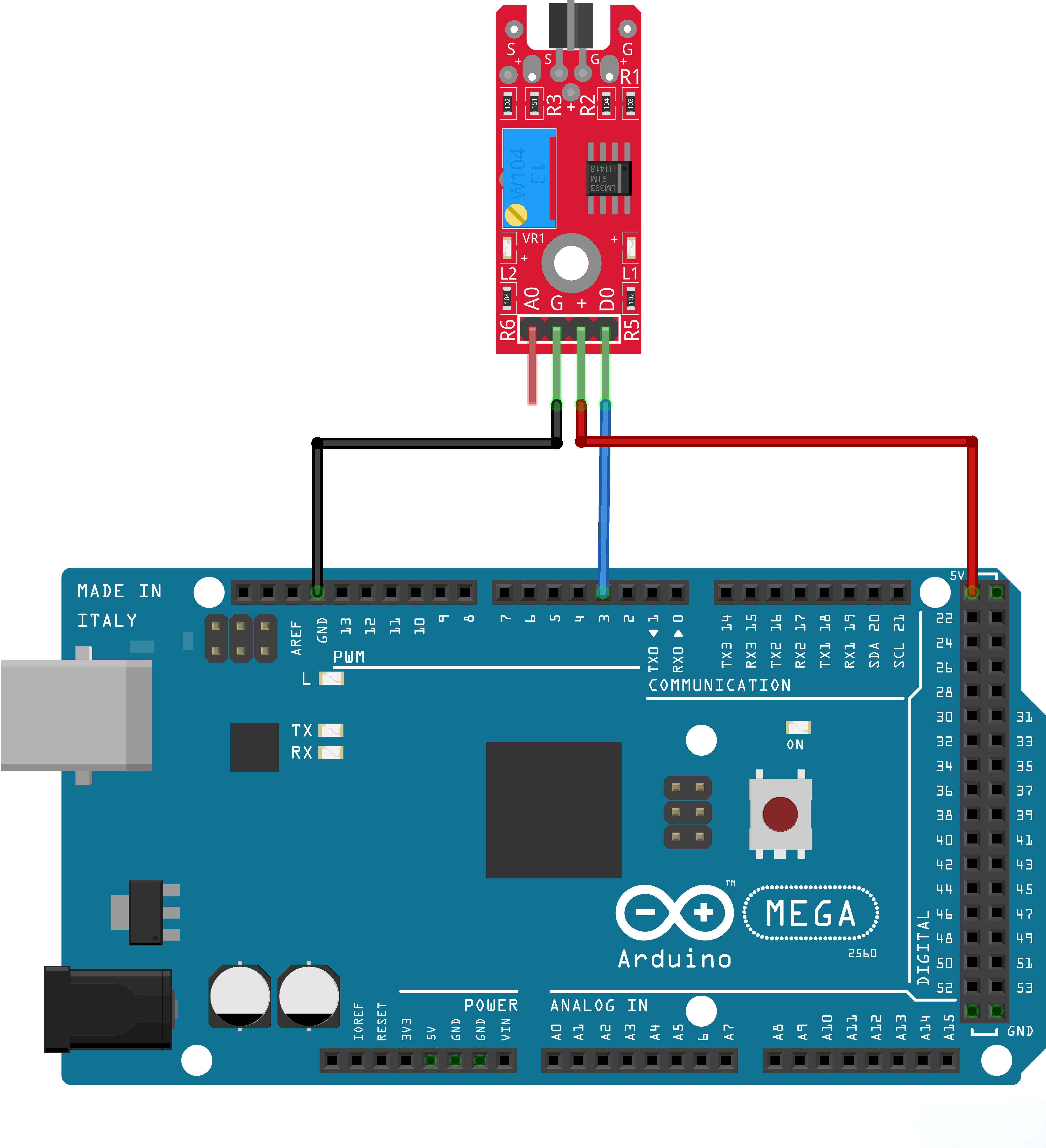
This piece of code is similar to the previous examples. It uses digitalRead() to read the level value of the sensor pin and turns the LED on or off according to the sensor status. This program takes ESP32 as the main controller. If you use other types of mainboards, just modify the corresponding pin numbers in the code.
If you need to acquire readings via pin A0, you can use the analogRead() function to obtain the corresponding analog value of this pin.