¶ Arduino Simple Remote Controller (ESP32 + UNO R4 WiFi)
Note: This tutorial uses ESP32 and UNO R4 WiFi boards. If you have two UNO R4 boards, you can also use them by configuring one in AP mode and the other in STA mode. For specific details, refer to the previous tutorial or simply modify the current code.
If you are using two ESP32 boards, please refer to the wiring tutorial below.
https://wiki.elegoo.com/en/oshw-getting-started-&-kits/dualboard-esp32
¶ Relevant Knowledge
¶ What is a Remote Control System?
A remote controller is a system that controls one device remotely through another. Common remote controls in daily life include: TV remotes, air conditioner remotes, garage door remotes, etc. This project is a typical "wireless remote control" application:
- Remote End (Transmitter): UNO R4 WiFi reads button states and sends commands via WiFi
- Transport Layer (Communication): Two boards communicate with each other through WiFi's TCP protocol
- Receiver End (Executor): ESP32 receives commands and controls the RGB LED and buzzer
Simple analogy: Just like pressing buttons on a TV remote changes channels/adjusts volume — the UNO R4 is the remote controller, the ESP32 is the "TV" being controlled, and WiFi is the invisible "signal line" between them.
¶ Project Architecture Overview (Dual-Board Collaboration)
This project consists of two boards, each with distinct roles that work together. This architecture is closer to real-world products than single-board projects.
| Board | Role | File Name | Core Function |
|---|---|---|---|
| ESP32 | Receiver (Controlled Device) | esp32.ino |
Creates WiFi hotspot, TCP server, controls RGB LED and buzzer |
| UNO R4 WiFi | Transmitter (Remote Controller) | unor4.ino |
Connects to hotspot, reads 5 buttons, sends control commands |
¶ Why Use a Dual-Board Architecture?
| Advantage | Description |
|---|---|
| Clear Division of Labor | Separation between the remote controller and the controlled device makes logic clear |
| Realistic | Real remote controls (TV, air conditioner) all use this structure |
| Strong Scalability | One receiver can connect to multiple remote controllers, and vice versa |
| High Learning Value | Learn AP/STA modes, TCP communication, button debouncing, and more at the same time |
| Decoupled Design | Modifying the remote controller code won't affect the receiver, and vice versa |
¶ ESP32 Board
ESP32 is a powerful, cost-effective IoT development board:
- Built-in WiFi and Bluetooth
- Dual-core processor, performance far exceeds the traditional Arduino UNO
- Supports multiple PWM output pins (for dimming, sound)
- In this project, the ESP32 acts as the "controlled device," creating a hotspot and waiting for remote controllers to connect
¶ RGB LED
An RGB LED integrates red (R), green (G), and blue (B) light-emitting chips internally:
- By adjusting the brightness of the R/G/B channels, various colors can be mixed
- This project presets 7 colors: red, green, blue, yellow, cyan, purple, white
- Divided into common cathode (common terminal to GND) and common anode (common terminal to VCC) types
Simple analogy: An RGB LED is like a "palette" — mixing red, green, and blue in different proportions can produce any color.
¶ Buzzer
Buzzers are divided into active and passive types:
- Active Buzzer: Sounds when powered on, only needs on/off control
- Passive Buzzer: Requires a square wave signal to produce sound, pitch can be controlled by frequency
- This project uses a passive buzzer, driven by a 1000Hz square wave from the
tone()function
Simple analogy: A passive buzzer is like a "small speaker" — giving it electrical signals of different frequencies produces sounds of different pitches.
¶ Button Debounce
Button debouncing is an important technique for handling mechanical button bounce:
- When mechanical buttons are pressed/released, the contacts produce several milliseconds of "bounce," causing multiple rapid state changes to be read
- Without debouncing, pressing a button once may be recognized as multiple presses
- This project uses
millis()timing to wait 50ms after detecting a level change before confirming the state
Simple analogy: When pressing a button, your finger may tremble slightly. Debouncing is about "waiting for your hand to steady before determining whether you actually pressed it."
¶ TCP Communication Protocol
TCP (Transmission Control Protocol) is a reliable transport layer protocol:
- Communication can only be established after a connection is set up (three-way handshake)
- Guarantees data arrives in order and without loss
- This project uses TCP for "command-feedback" style communication
Communication Flow:
- ESP32 creates a hotspot and starts a TCP server (port 8080)
- UNO R4 connects to the hotspot, then connects to ESP32's TCP server
- UNO R4 presses button → sends command string (e.g.,
RGB_ON) - ESP32 receives command → executes action → returns feedback (e.g.,
OK: RGB_ON)
¶ Library Installation Guide
This project uses few libraries, most of which are built into the board.
¶ Installing ESP32 Board Support
- Open Arduino IDE
- Click menu File → Preferences
- In "Additional Boards Manager URLs", add the ESP32 package address:
https://dl.espressif.com/dl/esp32/esp32-arduino-index.json - Click menu Tools → Board → Boards Manager
- Search for
esp32, install esp32 by Espressif Systems
¶ Key Function Reference
¶ ESP32 WiFi and TCP Related Functions
| Function/Variable | Description | Role in This Project |
|---|---|---|
WiFi.softAP(ssid, password) |
Start AP hotspot | ESP32 creates a hotspot named ESP32_AP |
WiFi.softAPIP() |
Get AP mode IP | Returns default IP 192.168.4.1 |
WiFiServer server(8080) |
Create TCP server | Listens on port 8080 for connections |
server.begin() |
Start server | Start accepting client connections |
server.hasClient() |
Check for new connections | Determine if a remote controller requests connection |
server.available() |
Accept connection | Get client object |
client.connected() |
Check connection status | Confirm if remote controller is online |
client.available() |
Check for data | Determine if a command has been received |
client.readStringUntil('\n') |
Read a line of data | Read command sent by remote controller |
client.println(...) |
Send a line of data | Return feedback to remote controller |
¶ UNO R4 WiFi and TCP Related Functions
| Function/Variable | Description | Role in This Project |
|---|---|---|
WiFi.status() |
Check WiFi status | Determine if connected successfully / module exists |
WiFi.begin(ssid, password) |
Start STA mode | Connect to ESP32's hotspot |
WiFi.localIP() |
Get local IP | View assigned IP address |
WiFiClient client |
Create TCP client | Used to connect to ESP32 server |
client.connect(ip, port) |
Connect to server | Connect to ESP32's port 8080 |
client.println(cmd) |
Send command | Send button command to ESP32 |
client.connected() |
Check connection status | Determine if reconnection is needed |
¶ ESP32 RGB LED and Buzzer Functions
| Function | Description | Role in This Project |
|---|---|---|
analogWrite(pin, value) |
PWM output | Controls brightness of RGB's three channels (0~255) |
setRGB(r, g, b) |
Custom function | Set RGB LED color (compatible with common cathode/anode) |
updateRGB() |
Custom function | Refresh RGB LED based on switch state |
tone(pin, freq) |
Output square wave | Make passive buzzer sound at 1000Hz |
noTone(pin) |
Stop square wave | Stop buzzer from sounding |
¶ UNO R4 Button and Debounce Functions
| Function/Variable | Description | Role in This Project |
|---|---|---|
pinMode(pin, INPUT_PULLUP) |
Enable internal pull-up | Button pressed is low level, released is high level |
digitalRead(pin) |
Read pin level | Get current button state |
millis() |
Milliseconds since boot | Used for debounce timing |
checkButton(index) |
Custom function | Debounce detection and trigger command sending |
sendCommand(cmd) |
Custom function | Send command via TCP |
connectToServer() |
Custom function | Connect to ESP32 server |
debounceDelay |
Debounce delay (50ms) | Time threshold for waiting for level to stabilize |
¶ Command Protocol Table
| Command String | Direction | Function | ESP32 Feedback |
|---|---|---|---|
REMOTE_CONNECTED |
UNO R4 → ESP32 | Connection handshake | OK: CONNECTED |
RGB_ON |
UNO R4 → ESP32 | Turn on RGB LED | OK: RGB_ON |
RGB_OFF |
UNO R4 → ESP32 | Turn off RGB LED | OK: RGB_OFF |
RGB_COLOR |
UNO R4 → ESP32 | Switch to next color | OK: RGB_COLOR or ERR: LIGHT_IS_OFF |
BUZZ_ON |
UNO R4 → ESP32 | Buzzer on | OK: BUZZ_ON |
BUZZ_OFF |
UNO R4 → ESP32 | Buzzer off | OK: BUZZ_OFF |
¶ Color Table (Built into ESP32)
| Index | Color | R | G | B |
|---|---|---|---|---|
| 0 | Red | 255 | 0 | 0 |
| 1 | Green | 0 | 255 | 0 |
| 2 | Blue | 0 | 0 | 255 |
| 3 | Yellow | 255 | 255 | 0 |
| 4 | Cyan | 0 | 255 | 255 |
| 5 | Purple | 255 | 0 | 255 |
| 6 | White | 255 | 255 | 255 |
Each press of the "Color Adjust" button increments the color index by 1, cycling from 6 back to 0.
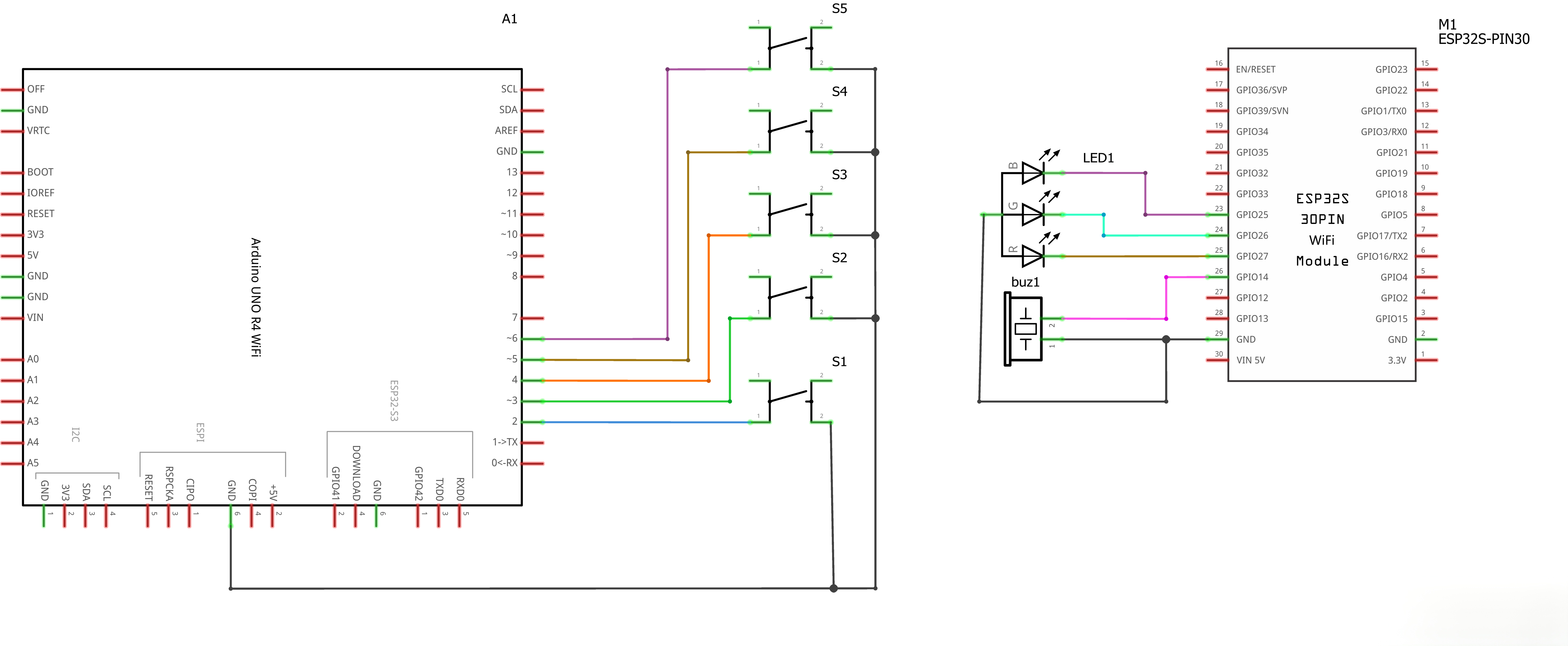
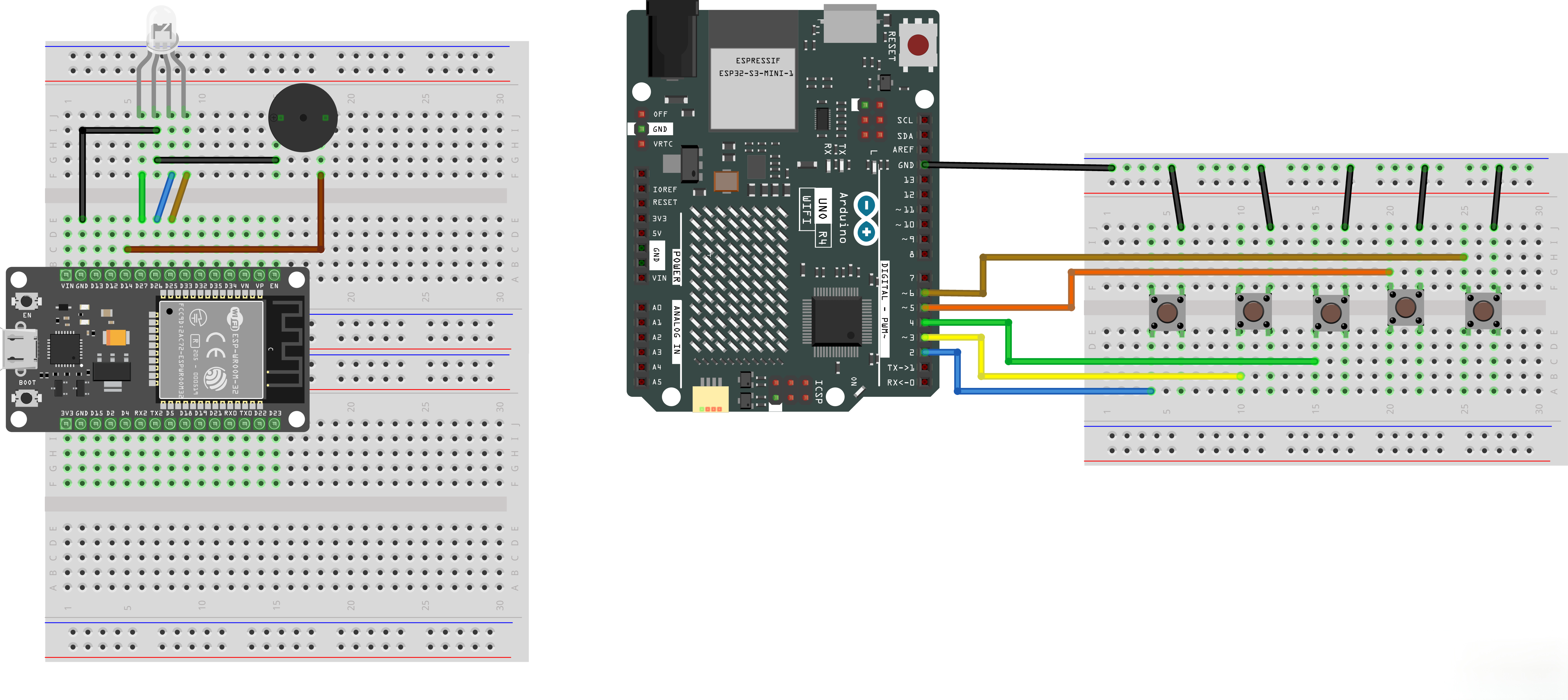
¶ Connection Schematic
¶ Wiring diagram
¶ Complete Code Analysis
¶ 1. ESP32 Receiver Program (esp32.ino)
The ESP32 is the controlled device, responsible for creating a hotspot, receiving commands, and controlling the RGB LED and buzzer.
¶ 1. Header Includes and Pin Definitions
#include <WiFi.h>

const char* ssid = "ESP32_AP";
const char* password = "12345678";

// RGB LED Pins
const int PIN_R = 27;
const int PIN_G = 26;
const int PIN_B = 25;
const int PIN_BUZZER = 14;

// RGB type: false = common cathode, true = common anode
const bool COMMON_ANODE = false;

WiFiServer server(8080);
WiFiClient client;

bool rgbOn = false;
int colorIndex = 0;

// Color table (R, G, B)
const int colors[][3] = {
  {255, 0, 0},    // 0 Red
  {0, 255, 0},    // 1 Green
  {0, 0, 255},    // 2 Blue
  {255, 255, 0},  // 3 Yellow
  {0, 255, 255},  // 4 Cyan
  {255, 0, 255},  // 5 Purple
  {255, 255, 255} // 6 White
};
const int numColors = 7;

// Buzzer state
bool buzzerOn = false;
Code Description:
ssid/password: Hotspot name and password, UNO R4 must use the same parameters to connectPIN_R/G/B: RGB LED's three color channels connected to ESP32's pins 27/26/25 (all support PWM)PIN_BUZZER: Buzzer connected to pin 14COMMON_ANODE: RGB LED type switch,falsefor common cathode,truefor common anodecolors[][]: Preset RGB value table for 7 colorsserver(8080): Create TCP server on port 8080 (avoids port 80 for easier distinction)
¶ 2. setup() Initialization Function
void setup() {
  Serial.begin(115200);
  delay(1000);

  pinMode(PIN_R, OUTPUT);
  pinMode(PIN_G, OUTPUT);
  pinMode(PIN_B, OUTPUT);
  pinMode(PIN_BUZZER, OUTPUT);

  setRGB(0, 0, 0);
  noTone(PIN_BUZZER);

  Serial.println("\n=== ESP32 Receiver ===");

  WiFi.softAP(ssid, password);
  IPAddress IP = WiFi.softAPIP();
  Serial.print("AP IP: ");
  Serial.println(IP);

  server.begin();
  Serial.println("TCP Server: 8080");
}
Step Breakdown:
- Serial Initialization: Baud rate 115200, used for debug output
- Pin Configuration: 4 pins set to output mode
- Initial State: RGB LED off, buzzer muted, to avoid accidental actions at power-on
- Start AP Hotspot:
WiFi.softAP()creates hotspot, default IP is192.168.4.1 - Start TCP Server:
server.begin()starts listening on port 8080
¶ 3. setRGB() Color Setting Function
void setRGB(int r, int g, int b) {
  if (COMMON_ANODE) {
    analogWrite(PIN_R, 255 - r);
    analogWrite(PIN_G, 255 - g);
    analogWrite(PIN_B, 255 - b);
  } else {
    analogWrite(PIN_R, r);
    analogWrite(PIN_G, g);
    analogWrite(PIN_B, b);
  }
}
Code Logic Analysis:
analogWrite(PIN_R, r);
Common cathode RGB LED writing: The common terminal connects to GND, and the pin outputs high level (higher value = brighter), so you can write r/g/b directly. analogWrite(pin, value) outputs a PWM wave with value ranging from 0 to 255 to control brightness.
analogWrite(PIN_R, 255 - r);
Common anode RGB LED writing: The common terminal connects to VCC, and the pin outputs low level (lower value = brighter), so you need to invert the value with 255 - r — if you want red brightness of 255 (brightest), you actually write 255 - 255 = 0 (lowest level). This is the part about common anode that most confuses beginners — just remember to "invert."
if (COMMON_ANODE) { ... } else { ... }
Through the COMMON_ANODE switch, one piece of code is compatible with both types of RGB LEDs without changing wiring. Before use, just set this variable to true (common anode) or false (common cathode) based on your RGB LED type.
¶ 4. updateRGB() State Refresh Function
void updateRGB() {
  if (!rgbOn) {
    setRGB(0, 0, 0);
    Serial.println("[Status] RGB OFF");
  } else {
    setRGB(colors[colorIndex][0], colors[colorIndex][1], colors[colorIndex][2]);
    Serial.print("[Status] RGB ON Color#");
    Serial.print(colorIndex);
    Serial.print(" (");
    Serial.print(colors[colorIndex][0]);
    Serial.print(",");
    Serial.print(colors[colorIndex][1]);
    Serial.print(",");
    Serial.print(colors[colorIndex][2]);
    Serial.println(")");
  }
}
Code Logic Analysis:
- Determines whether to turn on or off based on the
rgbOnswitch state - When turning on, takes the RGB value corresponding to the current
colorIndexfrom thecolorstable - Prints the current color index and specific RGB values to serial port for debugging
- This function is called uniformly every time the light is switched or color is adjusted, ensuring display state matches variables
¶ 5. handleCommand() Command Processing Function (Core)
void handleCommand(String cmd) {
  cmd.trim();
  Serial.print("[Command] ");
  Serial.println(cmd);

  if (cmd == "RGB_ON") {
    rgbOn = true;
    updateRGB();
    client.println("OK: RGB_ON");
  }
  else if (cmd == "RGB_OFF") {
    rgbOn = false;
    updateRGB();
    client.println("OK: RGB_OFF");
  }
  else if (cmd == "RGB_COLOR") {
    // Only adjust color when light is on
    if (!rgbOn) {
      Serial.println("[Rejected] Light is off, color adjustment invalid");
      client.println("ERR: LIGHT_IS_OFF");
      return;
    }
    colorIndex = (colorIndex + 1) % numColors;
    updateRGB();
    client.println("OK: RGB_COLOR");
  }
  else if (cmd == "BUZZ_ON") {
    buzzerOn = true;
    tone(PIN_BUZZER, 1000);  // 1000Hz square wave
    Serial.println("[Status] Buzzer ON (1000Hz)");
    client.println("OK: BUZZ_ON");
  }
  else if (cmd == "BUZZ_OFF") {
    buzzerOn = false;
    noTone(PIN_BUZZER);  // Stop sound
    digitalWrite(PIN_BUZZER, LOW);
    Serial.println("[Status] Buzzer OFF");
    client.println("OK: BUZZ_OFF");
  }
  else if (cmd == "REMOTE_CONNECTED") {
    client.println("OK: CONNECTED");
  }
  else {
    client.println("ERR: UNKNOWN");
  }
}
Code Logic Step-by-Step Analysis:
cmd.trim();
Removes whitespace characters (like \r, spaces) from the beginning and end of the command string to avoid match failures. Since the remote controller sends with println() which automatically appends \r\n, the command read by ESP32 may have a trailing \r. Without removing it, cmd == "RGB_ON" would fail to match due to the extra \r at the end.
if (cmd == "RGB_ON") { ... }
Uses == for precise string comparison, executing the corresponding branch on successful match. This approach requires command strings to be completely identical, so command names in the protocol (like RGB_ON, BUZZ_OFF) must be spelled uniformly in both pieces of code.
else if (cmd == "RGB_COLOR") {
  if (!rgbOn) {
    Serial.println("[Rejected] Light is off, color adjustment invalid");
    client.println("ERR: LIGHT_IS_OFF");
    return;
  }
  ...
}
RGB_COLOR safety check: Before adjusting color, first checks rgbOn. If the light is off, it directly returns ERR: LIGHT_IS_OFF without executing the color adjustment. This is a deliberately designed protection logic — avoiding "adjusting colors while the light is off," which would cause unpredictable colors on the next power-on. return exits the function early, skipping subsequent color switching code.
colorIndex = (colorIndex + 1) % numColors;
Color cycling: Uses the modulo operation % to implement a cycle of 0→1→2→...→6→0. When colorIndex is 6, 6 + 1 = 7, 7 % 7 = 0, returning to the first color. This approach is simpler than using if judgments and is a common technique for loop counters.
tone(PIN_BUZZER, 1000);      // 1000Hz square wave
...
noTone(PIN_BUZZER);          // Stop sound
digitalWrite(PIN_BUZZER, LOW);
Buzzer control: tone(pin, 1000) outputs a 1000Hz square wave to make the passive buzzer sound; noTone(pin) stops the square wave output. The additional call to digitalWrite(PIN_BUZZER, LOW) pulls the pin level low to ensure the buzzer is completely muted, avoiding residual signals causing slight noise.
client.println("OK: RGB_ON");
Feedback mechanism: After processing each command, returns OK: or ERR: feedback to the remote controller via client.println(). The remote controller can use this to determine whether the command executed successfully (e.g., it will receive ERR: LIGHT_IS_OFF when color adjustment fails).
else { client.println("ERR: UNKNOWN"); }
Unknown command handling: This branch executes when all if/else if fail to match, returning ERR: UNKNOWN. This helps troubleshoot protocol errors — if the remote controller misspells a command name, it can be immediately discovered from the feedback.
¶ 6. loop() Main Loop Function
void loop() {
  if (server.hasClient()) {
    if (!client || !client.connected()) {
      if (client) client.stop();
      client = server.available();
      Serial.println("[Network] Remote controller connected");
    }
  }

  if (client && client.connected() && client.available()) {
    String cmd = client.readStringUntil('\n');
    handleCommand(cmd);
  }
}
Core Function Analysis:
Core 1: Client Connection Management
if (server.hasClient()) {
  if (!client || !client.connected()) {
    if (client) client.stop();
    client = server.available();
  }
}
server.hasClient()detects whether a new client requests connection- Only accepts new connections when there is no active client currently, to avoid overwriting the client currently communicating
- If the old client has disconnected, first
stop()to release resources before accepting a new connection
Core 2: Command Receiving and Processing
if (client && client.connected() && client.available()) {
  String cmd = client.readStringUntil('\n');
  handleCommand(cmd);
}
- Triple condition check: client exists, connected, and has data readable
readStringUntil('\n')reads until the newline character, corresponding to the remote controller'sprintln()(which automatically adds\n)- After receiving the command, hands it to
handleCommand()for processing
¶ 2. UNO R4 Remote Controller Program (unor4.ino)
The UNO R4 is the remote controller, responsible for connecting to the ESP32 hotspot, reading buttons, and sending commands via TCP.
¶ 1. Header Includes and Pin Definitions
#include <WiFiS3.h>

// Network Configuration
const char* ssid = "ESP32_AP";
const char* password = "12345678";
const char* serverIP = "192.168.4.1";
const int serverPort = 8080;

// Button Pins
const int BTN_RGB_ON    = 2;
const int BTN_RGB_OFF   = 3;
const int BTN_RGB_COLOR = 4;
const int BTN_BUZZ_ON   = 5;
const int BTN_BUZZ_OFF  = 6;

const int btnPins[] = {BTN_RGB_ON, BTN_RGB_OFF, BTN_RGB_COLOR, BTN_BUZZ_ON, BTN_BUZZ_OFF};
const char* btnCmds[] = {"RGB_ON", "RGB_OFF", "RGB_COLOR", "BUZZ_ON", "BUZZ_OFF"};

WiFiClient client;
unsigned long lastReconnectAttempt = 0;

// Debounce Variables (Key Fix)
bool lastReading[5] = {HIGH, HIGH, HIGH, HIGH, HIGH};  // Last raw reading values
bool buttonState[5] = {HIGH, HIGH, HIGH, HIGH, HIGH};  // Stable state
unsigned long lastDebounceTime[5] = {0, 0, 0, 0, 0};
const unsigned long debounceDelay = 50;
Code Description:
ssid/password: Must be exactly the same as the ESP32 sideserverIP: ESP32's default IP in AP mode192.168.4.1serverPort: Consistent with ESP32 server port (8080)btnPins[]/btnCmds[]: Uses two arrays to correspond "pin numbers" with "command strings" one-to-one, avoiding writing 5 copies of repetitive code- Debounce variables use array form, with each button independently maintaining a set of debounce states
lastReconnectAttempt: Records the last reconnection time to avoid frequent reconnections
¶ 2. setup() Initialization Function
void setup() {
  Serial.begin(115200);
  while (!Serial) { ; }
  delay(1000);

  for (int i = 0; i < 5; i++) {
    pinMode(btnPins[i], INPUT_PULLUP);
  }

  Serial.println("\n=== UNO R4 Remote Controller ===");

  if (WiFi.status() == WL_NO_MODULE) {
    Serial.println("WiFi module not found!");
    while (true);
  }

  Serial.print("Connecting WiFi");
  WiFi.begin(ssid, password);
  int attempts = 0;
  while (WiFi.status() != WL_CONNECTED && attempts < 30) {
    delay(500);
    Serial.print(".");
    attempts++;
  }

  if (WiFi.status() == WL_CONNECTED) {
    Serial.print("\nWiFi connected, IP: ");
    Serial.println(WiFi.localIP());
  } else {
    Serial.println("\nWiFi connection failed!");
  }
}
Step Breakdown:
- Serial Initialization:
while (!Serial)waits for serial port to be ready (UNO R4 specific) - Button Pin Configuration: Loop sets 5 pins to
INPUT_PULLUP(internal pull-up). Button one end connects to pin, the other end to GND. When pressed, it becomes low level - WiFi Module Detection:
WiFi.status() == WL_NO_MODULEchecks if hardware exists; if not, enters an infinite loop - Connect WiFi:
WiFi.begin()starts STA mode to connect to ESP32 hotspot, retries up to 30 times (500ms each, 15 seconds total) - Print Results: On success, displays local IP; on failure, gives a prompt (subsequent
loop()will continuously reconnect to the server)
¶ 3. connectToServer() Connection Function
void connectToServer() {
  Serial.print("Connecting to ESP32...");
  if (client.connect(serverIP, serverPort)) {
    Serial.println("Success!");
    client.println("REMOTE_CONNECTED");
  } else {
    Serial.println("Failed, retrying in 5 seconds");
  }
}
Code Logic Analysis:
client.connect(ip, port)initiates a TCP connection to ESP32- After successful connection, immediately sends the
REMOTE_CONNECTEDhandshake command. ESP32 will reply withOK: CONNECTED - Connection failure doesn't block; the main loop retries every 5 seconds
¶ 4. sendCommand() Send Command Function
void sendCommand(const char* cmd) {
  if (client.connected()) {
    client.println(cmd);
    Serial.print("[Sent] ");
    Serial.println(cmd);
  } else {
    Serial.println("[Error] Not connected, command not sent");
  }
}
Code Logic Analysis:
- Before sending, checks
client.connected()first to avoid writing data to an already disconnected connection println(cmd)sends the command and automatically appends\n, corresponding to ESP32'sreadStringUntil('\n')- Synchronously prints the sent content to serial port for debugging
¶ 5. checkButton() Button Debounce Detection Function (Core)
void checkButton(int index) {
  bool reading = digitalRead(btnPins[index]);

  // If reading value changes, reset debounce timer
  if (reading != lastReading[index]) {
    lastDebounceTime[index] = millis();
  }

  // Debounce time elapsed, update stable state
  if ((millis() - lastDebounceTime[index]) > debounceDelay) {
    if (reading != buttonState[index]) {
      buttonState[index] = reading;

      // Press event (low level, because INPUT_PULLUP is used)
      if (buttonState[index] == LOW) {
        Serial.print("[Button] ");
        Serial.println(btnCmds[index]);
        sendCommand(btnCmds[index]);
      }
    }
  }

  lastReading[index] = reading;
}
Code Logic Step-by-Step Analysis:
bool reading = digitalRead(btnPins[index]);
Read current level: digitalRead() gets the real-time level of the button pin. Since INPUT_PULLUP is used, the button is HIGH when not pressed and LOW when pressed.
if (reading != lastReading[index]) {
  lastDebounceTime[index] = millis();
}
Detect level change: If the current reading is different from lastReading, it indicates that the level has changed (could be mechanical bounce or a real press). At this point, reset the debounce timer lastDebounceTime to the current time, starting a new round of "waiting for stability" timing.
if ((millis() - lastDebounceTime[index]) > debounceDelay) {
  ...
}
Wait for debounce: Use millis() - lastDebounceTime to calculate how much time has elapsed since the last change. Only when it exceeds debounceDelay (50ms) is the level considered stable. 50ms is sufficient to filter out mechanical bounce (typically only 5~10ms) without affecting response speed. This is the key to non-blocking timing — without delay(), the main loop can continue polling other buttons.
if (reading != buttonState[index]) {
  buttonState[index] = reading;
  ...
}
Update stable state: Write the stable level to buttonState and compare it with the previously saved state. Only when an "effective change" occurs (stable level is different from last time) does it continue processing, avoiding repeated triggers in each loop iteration.
if (buttonState[index] == LOW) {
  Serial.print("[Button] ");
  Serial.println(btnCmds[index]);
  sendCommand(btnCmds[index]);
}
Trigger press event: Since INPUT_PULLUP is used, pressing is LOW. A command is sent only once when the level changes from HIGH to LOW (the moment of pressing). This is "edge-triggered" — holding the button won't repeatedly send, and releasing won't trigger either, preventing one press from being recognized as multiple.
lastReading[index] = reading;
Save reading value: Store the current level in lastReading to prepare for the next loop's comparison. This step must be placed at the end of the function to ensure the entire debounce logic uses the "previous" reading value.
Design Features:
- Edge-Triggered: Only triggers once at the moment of pressing; holding won't repeatedly send, and releasing won't trigger
- Independent Debounce Per Button: Each of the 5 buttons has its own
lastReading,buttonState, andlastDebounceTime, without interference - Non-Blocking Design: Uses
millis()timing withoutdelay(), the main loop can quickly poll all buttons - 50ms Threshold: Empirical value, sufficient to filter mechanical bounce (typically 5~10ms) without affecting response speed
¶ 6. loop() Main Loop Function
void loop() {
  // Maintain TCP connection
  if (!client.connected()) {
    if (millis() - lastReconnectAttempt > 5000) {
      lastReconnectAttempt = millis();
      connectToServer();
    }
  }

  // Check 5 buttons
  for (int i = 0; i < 5; i++) {
    checkButton(i);
  }

  // Receive ESP32 feedback
  if (client.connected() && client.available()) {
    String response = client.readStringUntil('\n');
    response.trim();
    Serial.print("[Received] ");
    Serial.println(response);
  }
}
Core Function Analysis:
Core 1: Connection Maintenance and Auto-Reconnection
if (!client.connected()) {
  if (millis() - lastReconnectAttempt > 5000) {
    lastReconnectAttempt = millis();
    connectToServer();
  }
}
- Each loop iteration checks whether the TCP connection is still active
- When disconnected, attempts reconnection every 5 seconds to avoid frequent reconnections consuming resources
- Uses
millis()for timing intervals, non-blocking
Core 2: Button Polling
for (int i = 0; i < 5; i++) {
  checkButton(i);
}
- Each loop iteration sequentially checks 5 buttons
- The array-based design keeps the code simple; adding a new button only requires adding an item to the array
Core 3: Receiving Feedback
if (client.connected() && client.available()) {
  String response = client.readStringUntil('\n');
  response.trim();
  Serial.print("[Received] ");
  Serial.println(response);
}
- Reads the
OK:/ERR:feedback returned by ESP32 response.trim()removes trailing\rand other whitespace characters- Prints to serial port to confirm successful command execution
¶ Hardware Wiring Guide
¶ ESP32 Receiver Wiring
| Component | Pin | ESP32 Pin | Description |
|---|---|---|---|
| RGB LED - R | R | GPIO 27 | Red channel (PWM) |
| RGB LED - G | G | GPIO 26 | Green channel (PWM) |
| RGB LED - B | B | GPIO 25 | Blue channel (PWM) |
| RGB LED - Common | + / - | VCC or GND | Common anode to VCC, common cathode to GND |
| Buzzer | + | GPIO 14 | Passive buzzer signal end |
| Buzzer | - | GND | Ground |
Note: Each RGB channel is recommended to have a 220Ω current-limiting resistor in series to prevent LED or board damage from excessive current.
¶ UNO R4 Remote Controller Wiring
| Button | Pin | UNO R4 Pin | Other End |
|---|---|---|---|
| Button 1 (RGB On) | - | D2 | GND |
| Button 2 (RGB Off) | - | D3 | GND |
| Button 3 (Color Adjust) | - | D4 | GND |
| Button 4 (Buzzer On) | - | D5 | GND |
| Button 5 (Buzzer Off) | - | D6 | GND |
Note: Buttons don't need external resistors. The code uses
INPUT_PULLUPinternal pull-up. One end of the button connects to the digital pin, the other end to GND.
¶ Operation Steps Guide
¶ Step 1: Install Board Support
- Open Arduino IDE
- Install ESP32 board core
- Install Arduino UNO R4 board core
¶ Step 2: Connect Hardware
- Connect the ESP32 side's RGB LED and buzzer according to the "Hardware Wiring Guide"
- Connect the UNO R4 side's 5 buttons according to the "Hardware Wiring Guide"
- Confirm the RGB LED type (common cathode/anode) and set
COMMON_ANODEinesp32.ino
¶ Step 3: Flash ESP32 Receiver
- Connect ESP32 to computer via USB
- Select in Arduino IDE:
- Board: ESP32 Dev Module (or your specific model)
- Port: Correct COM port
- Open
esp32.ino, click Upload - After flashing completes, open serial monitor (115200), confirm it displays
AP IP: 192.168.4.1
¶ Step 4: Flash UNO R4 Remote Controller
- Connect UNO R4 WiFi to computer via USB
- Select in Arduino IDE:
- Board: Arduino UNO R4 WiFi
- Port: Correct COM port
- Open
unor4.ino, click Upload - After flashing completes, open serial monitor (115200), confirm WiFi connection is successful
¶ Step 5: Observe Startup Process
ESP32 Serial Should Display:
=== ESP32 Receiver ===
AP IP: 192.168.4.1
TCP Server: 8080
UNO R4 Serial Should Display:
=== UNO R4 Remote Controller ===
Connecting WiFi.......
WiFi connected, IP: 192.168.4.2
Connecting to ESP32...Success!
¶ Step 6: Start Remote Control
- Confirm both boards' serial ports display successful connections
- Press buttons on UNO R4:
- Press "RGB On" button → ESP32's RGB LED lights up (default red)
- Press "Color Adjust" button → Colors switch sequentially: red→green→blue→yellow→cyan→purple→white→red...
- Press "RGB Off" button → RGB LED turns off
- Press "Buzzer On" button → Buzzer sounds (1000Hz)
- Press "Buzzer Off" button → Buzzer stops
- Observe the
[Sent]and[Received]messages on UNO R4's serial port to confirm command execution status
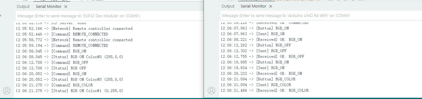
¶ Expected Serial Output
¶ ESP32 Receiver Serial
At Startup:
=== ESP32 Receiver ===
AP IP: 192.168.4.1
TCP Server: 8080
After Remote Controller Connects:
[Network] Remote controller connected
[Command] REMOTE_CONNECTED
When Pressing Buttons:
[Command] RGB_ON
[Status] RGB ON Color#0 (255,0,0)
[Command] RGB_COLOR
[Status] RGB ON Color#1 (0,255,0)
[Command] RGB_COLOR
[Status] RGB ON Color#2 (0,0,255)
[Command] BUZZ_ON
[Status] Buzzer ON (1000Hz)
[Command] BUZZ_OFF
[Status] Buzzer OFF
[Command] RGB_OFF
[Status] RGB OFF
[Command] RGB_COLOR
[Rejected] Light is off, color adjustment invalid
¶ UNO R4 Remote Controller Serial
At Startup:
=== UNO R4 Remote Controller ===
Connecting WiFi.......
WiFi connected, IP: 192.168.4.2
Connecting to ESP32...Success!
[Received] OK: CONNECTED
When Pressing Buttons:
[Button] RGB_ON
[Sent] RGB_ON
[Received] OK: RGB_ON
[Button] RGB_COLOR
[Sent] RGB_COLOR
[Received] OK: RGB_COLOR
[Button] BUZZ_ON
[Sent] BUZZ_ON
[Received] OK: BUZZ_ON
[Button] BUZZ_OFF
[Sent] BUZZ_OFF
[Received] OK: BUZZ_OFF
Auto-Reconnection After ESP32 Restart:
[Error] Not connected, command not sent
Connecting to ESP32...Success!
[Received] OK: CONNECTED
¶ Troubleshooting
¶ Frequently Asked Questions
Q1: Serial monitor displays garbled text?
A: Please confirm both serial monitors' baud rates are set to 115200. Note that ESP32 and UNO R4 require separate serial port windows (if only one serial window is available, you can switch ports to view).
Q2: UNO R4 prompts "WiFi module not found"?
A: Please check:
- Is the board selected as Arduino UNO R4 WiFi (not UNO R4 Minima)?
- Does the USB cable support data transmission (some cables can only charge)?
- Is the board core installed correctly?
Q3: UNO R4 keeps failing to connect to WiFi?
A: Please check:
- Has ESP32 been flashed and started (serial port should display
AP IP: 192.168.4.1)? - Are
ssidandpasswordexactly consistent with the ESP32 side? - Is the distance between the two boards too far (recommended within 5 meters)?
- Is ESP32 powered on (can't only rely on computer USB, need to confirm startup completion)?
Q4: UNO R4 connects to WiFi but can't connect to TCP server?
A: Please check:
- Is
serverIP192.168.4.1? - Is
serverPort8080(consistent with ESP32 side)? - Does ESP32 serial port display
TCP Server: 8080? - UNO R4 auto-reconnects every 5 seconds, wait a moment and observe if it recovers
Q5: RGB LED color is wrong or partially not lit?
A: Please check:
- Is the RGB LED type set correctly: common cathode
COMMON_ANODE = false, common anodeCOMMON_ANODE = true? - Is the wiring correct (R→27, G→26, B→25)?
- Are current-limiting resistors (220Ω) in series?
- Is the common terminal connected correctly (common cathode to GND, common anode to VCC)?
Q6: Buzzer doesn't sound or sound is very faint?
A: Please check:
- Is a passive buzzer used (using
tone()with active buzzer may not sound or have abnormal sound)? - Is the wiring correct (signal end to GPIO 14)?
- Does the buzzer need extra power supply (some high-power buzzers require external power + transistor driver)?
Q7: Pressing a button once triggers multiple commands?
A: This is a debounce not working issue, please check:
- Is
debounceDelayset to 50 (milliseconds)? - Is the debounce code complete (three arrays:
lastReading,buttonState,lastDebounceTime)? - Is the button in poor contact (try replacing the button)?
Q8: Color adjustment button has no response?
A: This is a normal safety design. The RGB_COLOR command is only effective when the RGB LED is already on. Please press the "RGB On" button to turn on the light first, then press the "Color Adjust" button. When the light is off, color adjustment will return ERR: LIGHT_IS_OFF.
Q9: UNO R4 doesn't work after ESP32 restarts?
A: UNO R4 will detect the connection disconnection and auto-reconnect every 5 seconds. Please wait a few seconds; the serial port will display Connecting to ESP32...Success!. If it doesn't recover for a long time, press UNO R4's Reset button to restart.
¶ Modification Suggestions
¶ 1. Modify Hotspot Name and Password
Simultaneously modify in both esp32.ino and unor4.ino (must be consistent):
// esp32.ino
const char* ssid = "MyRemote_AP";
const char* password = "mypassword123";  // At least 8 characters

// unor4.ino
const char* ssid = "MyRemote_AP";
const char* password = "mypassword123";
¶ 2. Adapt Common Anode RGB LED
If your RGB LED is common anode (common terminal to VCC), modify esp32.ino:
const bool COMMON_ANODE = true; // Change to true
When wiring, the common terminal connects to 5V/VCC instead of GND; everything else remains unchanged.
¶ 3. Add More Colors
Add custom colors in the color table of esp32.ino:
const int colors[][3] = {
  {255, 0, 0},     // 0 Red
  {0, 255, 0},     // 1 Green
  {0, 0, 255},     // 2 Blue
  {255, 255, 0},   // 3 Yellow
  {0, 255, 255},   // 4 Cyan
  {255, 0, 255},   // 5 Purple
  {255, 255, 255}, // 6 White
  {255, 128, 0},   // 7 Orange (newly added)
  {128, 0, 255},   // 8 Blue-purple (newly added)
};
const int numColors = 9;  // Modify count synchronously
¶ 4. Modify Buzzer Pitch
Modify the frequency parameter of tone() in esp32.ino:
tone(PIN_BUZZER, 2000);   // 2000Hz, higher pitch
tone(PIN_BUZZER, 500);    // 500Hz, lower pitch
¶ 5. Add More Buttons
Extend the button array in unor4.ino:
const int BTN_EXTRA = 7;  // New button connects to D7
const int btnPins[] = {BTN_RGB_ON, BTN_RGB_OFF, BTN_RGB_COLOR, BTN_BUZZ_ON, BTN_BUZZ_OFF, BTN_EXTRA};
const char* btnCmds[] = {"RGB_ON", "RGB_OFF", "RGB_COLOR", "BUZZ_ON", "BUZZ_OFF", "EXTRA_CMD"};
Also add corresponding command handling in handleCommand() on the ESP32 side. Remember to synchronously modify the debounce array size.
¶ 6. Modify Debounce Sensitivity
Adjust the debounce delay in unor4.ino:
const unsigned long debounceDelay = 20;  // 20ms, faster response but weaker anti-bounce
const unsigned long debounceDelay = 100; // 100ms, stronger anti-bounce but slightly slower response
¶ 7. Modify TCP Port
Simultaneously modify in both pieces of code (must be consistent):
// esp32.ino
WiFiServer server(9090);  // Change to 9090

// unor4.ino
const int serverPort = 9090;  // Modify synchronously
¶ Notes (Known Code Key Points)
¶ Note 1: Network Parameters Must Be Consistent Across Both Codes
ssid, password, and serverPort in esp32.ino and unor4.ino must be completely identical, otherwise connection cannot be established. When modifying, please update both codes simultaneously.
¶ Note 2: RGB Color Adjustment Safety Check
The RGB_COLOR command is rejected when the light is off (returns ERR: LIGHT_IS_OFF). This is a deliberately designed protection logic to avoid "adjusting colors while the light is off" causing unpredictable colors on the next power-on. If you want the light to turn on automatically when adjusting color, you can modify it to:
else if (cmd == "RGB_COLOR") {
  rgbOn = true;  // Auto turn on light
  colorIndex = (colorIndex + 1) % numColors;
  updateRGB();
  client.println("OK: RGB_COLOR");
}
¶ Note 3: Passive vs Active Buzzer Differences
This project uses tone() / noTone() to control a passive buzzer. If you are using an active buzzer (sounds when powered on), you need to switch to digitalWrite():
// Active buzzer control method
else if (cmd == "BUZZ_ON") {
  buzzerOn = true;
  digitalWrite(PIN_BUZZER, HIGH);  // Sounds when powered on
  client.println("OK: BUZZ_ON");
}
else if (cmd == "BUZZ_OFF") {
  buzzerOn = false;
  digitalWrite(PIN_BUZZER, LOW);   // Stops when powered off
  client.println("OK: BUZZ_OFF");
}
¶ Note 4: Single Client Limitation
The WiFiClient client in ESP32 code is a global single object, accepting only one remote controller connection at a time. If you need to support multiple remote controllers connecting simultaneously, you need to switch to a WiFiClient array and modify the connection management logic.
¶ Note 5: Buttons Use Internal Pull-Up
UNO R4 code uses INPUT_PULLUP. One end of the button connects to the pin, the other end to GND — no external resistor is needed. Incorrectly connecting an external pull-up resistor may cause level conflicts. Pressed is LOW, released is HIGH.
¶ Note 6: ESP32 Pins Must Support PWM
The R/G/B pins of the RGB LED must select GPIOs that support PWM output. This project uses 27/26/25, which all support it. If switching to other pins, please check the ESP32 pin documentation to confirm support for analogWrite() / ledcWrite().
¶ Future Extensions
¶ 1. Add More Controlled Devices
Expand more output devices on the ESP32 side:
- Relay (control headlights, fans, and other home appliances)
- Servo motor (control curtains, door locks)
- Stepper motor (control rotating devices)
- LED strip (WS2812 full-color strip lights, can achieve flowing light effects)
¶ 2. Add Sensor Feedback
Add sensors on the ESP32 side to feed back status to the remote controller:
- DHT11 temperature and humidity sensor, remote controller displays environment data
- Light-dependent resistor, automatically adjust RGB LED brightness
- Infrared human sensing, trigger alarm
¶ 3. Support Multiple Remote Controllers
Modify ESP32 code to support multiple clients connecting simultaneously:
- Use
WiFiClient clients[N]array to manage multiple connections - Implement one-to-many broadcast control
¶ 4. Switch to UDP Protocol
Change TCP to UDP communication:
- UDP doesn't require establishing a connection, lower latency
- Suitable for scenarios requiring high real-time performance (such as remote control cars)
- But doesn't guarantee reliable data delivery, need to handle packet loss yourself
¶ 5. Create Mobile APP Remote Controller
Develop a mobile APP using MIT App Inventor or Flutter:
- Mobile phone connects to ESP32 hotspot
- APP interface provides virtual buttons
- Sends the same command strings via TCP
- Replaces the UNO R4 physical remote controller
¶ 6. Add OLED Display
Add an OLED screen on the UNO R4 remote controller side:
- Display current connection status
- Display feedback information returned by ESP32
- Display current RGB LED color and buzzer status
¶ 7. Low Power Optimization
Optimize for battery-powered scenarios:
- ESP32 enables sleep mode, enters Light Sleep when no commands
- UNO R4 button interrupt wake-up, sleeps when idle
- Extend battery life