¶ IR Receiver
¶ Overview
Using an IR Remote is a great way to have wireless control of your project.Infrared remotes are simple and easy to use. In this tutorial we will be connecting the IR receiver to the UNO,It is not necessary to use a specific library here; instead, write a program to parse which key of the infrared remote control is pressed when a signal is received.
In our sketch we will have all the IR Hexadecimal codes that are available on this remote, we will also detect if the code was recognized and also if we are holding down a key.
¶ Component Required:
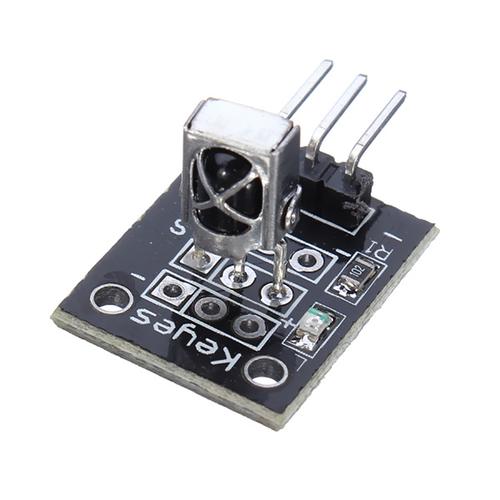
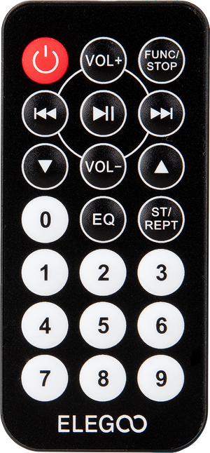
(1) x Elegoo Uno R4 WIFI
(1) x IR receiver module
(1) x IR remote
(3) x F-M wires (Female to Male DuPont wires)
¶ Component Introduction
¶ IR RECEIVER SENSOR:
IR detectors are little microchips with a photocell that are tuned to listen to infrared light. They are almost always used for remote control detection - every TV and DVD player has one of these in the front to listen for the IR signal from the clicker. Inside the remote control is a matching IR LED, which emits IR pulses to tell the TV to turn on, off or change channels. IR light is not visible to the human eye, which means it takes a little more work to test a setup.
There are a few difference between these and say a CdS Photocells:
IR detectors are specially filtered for IR light, they are not good at detecting visible light. On the other hand, photocells are good at detecting yellow/green visible light, and are not good at IR light.
IR detectors have a demodulator inside that looks for modulated IR at 38 KHz. Just shining an IR LED won't be detected, it has to be PWM blinking at 38KHz. Photocells do not have any sort of demodulator and can detect any frequency (including DC) within the response speed of the photocell (which is about 1KHz)
IR detectors are digital out - either they detect 38KHz IR signal and output low (0V) or they do not detect any and output high (5V). Photocells act like resistors, the resistance changes depending on how much light they are exposed to.
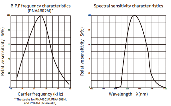
As you can see from these datasheet graphs, the peak frequency detection is at 38 KHz and the peak LED color is 940 nm. You can use from about 35 KHz to 41 KHz but the sensitivity will drop off so that it won't detect as well from afar. Likewise, you can use 850 to 1100 nm LEDs but they won't work as well as 900 to 1000nm so make sure to get matching LEDs! Check the datasheet for your IR LED to verify the wavelength.
Try to get a 940nm - remember that 940nm is not visible light!
¶ Connection Schematic
¶ Wiring diagram
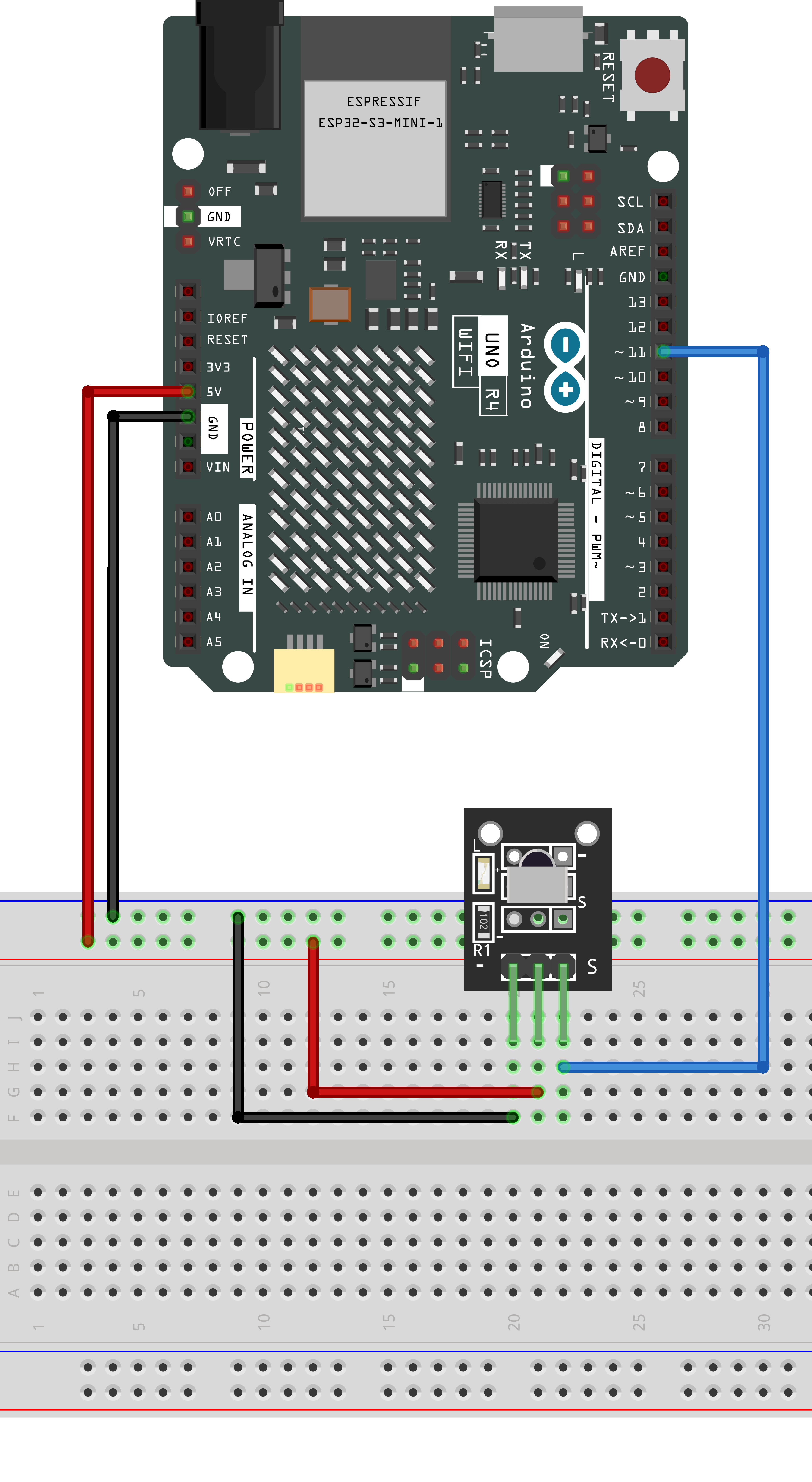
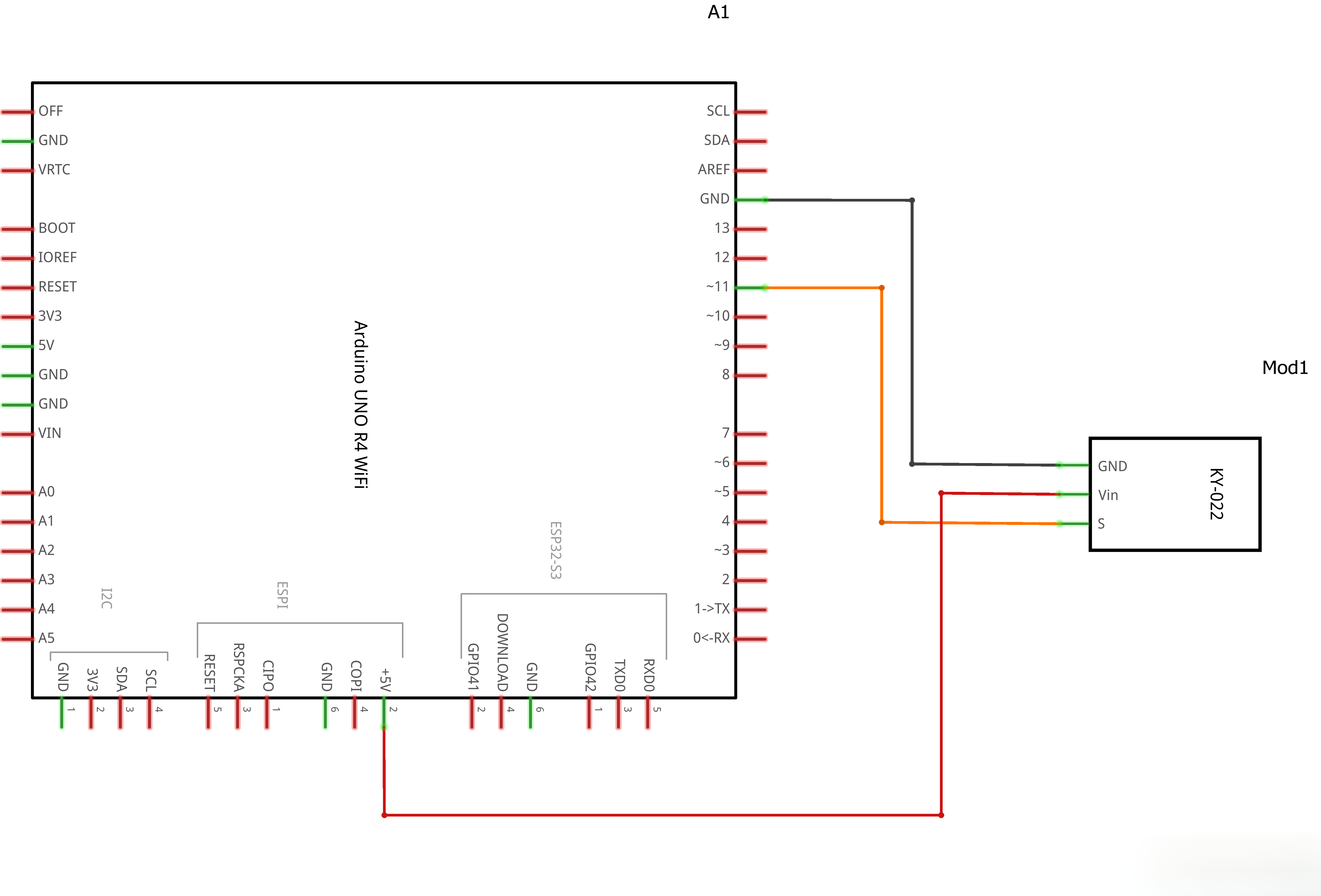
There are 3 connections to the IR Receiver.
The connections are: Signal, Voltage and Ground.
The“G”is the Ground,“Y”is signal, and“R”is Voltage 3.3V.
¶ Code
You can click the blue text link to download the program file to your local device, and double-click the file to open it after the download is complete. Please note: Before opening the file, ensure that you have installed the Arduino IDE development environment and completed the installation of relevant components such as the board support package and driver corresponding to the UNO development board. If you have any questions about this operation process, you can refer to the "part 1" chapter of the document for detailed guidance.
Click the Serial Monitor button to turn on the serial monitor.
¶ Pin Definition
const int IR = 11; // IR receiver data pin
Explanation: Defines the IR receiver data pin as digital pin 11. This is a critical configuration for infrared signal input, and all decoding operations are based on this pin.
¶ readPulse() Function
unsigned long readPulse(int level, unsigned long timeout = 20000) {
  unsigned long start = micros();
  while (digitalRead(IR) == level) {
    if (micros() - start > timeout) return 0;
  }
  return micros() - start;
}
Function: Measures the duration of a specified logic level (HIGH/LOW).
Parameters:
level: Target logic level, can beHIGHorLOWtimeout: Maximum waiting time in microseconds (default: 20000us = 20ms)
Return Value: Duration of the level in microseconds, 0 if timeout.
Working Principle:
- Use
micros()function to record the start time - Loop until the pin level changes or timeout occurs
- Return the actual measured time difference
Technical Point: The
micros()function is used to obtain microsecond-level precise timing, which is crucial for infrared decoding. Infrared signals require high timing precision, needing microsecond-level time measurement.
¶ loop() Function
void loop() {
  if (digitalRead(IR) == LOW) {
    unsigned long lowTime = readPulse(LOW);
    if (lowTime < 8000 || lowTime > 10000) return;

    unsigned long highTime = readPulse(HIGH);
    if (highTime < 4000 || highTime > 5000) return;

    unsigned long code = 0;
    for (int i = 0; i < 32; i++) {
      unsigned long bitLow = readPulse(LOW);
      if (bitLow < 400 || bitLow > 700) return;

      unsigned long bitHigh = readPulse(HIGH);
      if (bitHigh == 0) return;

      code <<= 1;
      if (bitHigh > 1000) code |= 1;
      else code |= 0;
    }

    Serial.print("Received code: 0x");
    Serial.println(code, HEX);

    switch (code) {
      case 0xFFA25D: Serial.println("POWER"); break;
      case 0xFFE21D: Serial.println("FUNC/STOP"); break;
      // ... other buttons
      case 0xFFFFFFFF: Serial.println("REPEAT"); break;
      default: Serial.println("OTHER BUTTON"); break;
    }

    delay(150);
  }
}
Function: Main loop that continuously receives and decodes infrared signals.
Decoding Process:
¶ 1. Detect Leader Code
if (digitalRead(IR) == LOW) {
  unsigned long lowTime = readPulse(LOW);
  if (lowTime < 8000 || lowTime > 10000) return;

  unsigned long highTime = readPulse(HIGH);
  if (highTime < 4000 || highTime > 5000) return;
}
NEC Protocol Leader Code Characteristics:
- LOW level duration: approximately 9000us (validation range: 8000~10000us)
- HIGH level duration: approximately 4500us (validation range: 4000~5000us)
Explanation: The IR receiver outputs HIGH level when no signal is present. When a LOW level is detected, it indicates a potential infrared signal. By validating the leader code, interference signals can be filtered out.
¶ 2. Read 32-bit Data
unsigned long code = 0;
for (int i = 0; i < 32; i++) {
  unsigned long bitLow = readPulse(LOW);
  if (bitLow < 400 || bitLow > 700) return;

  unsigned long bitHigh = readPulse(HIGH);
  if (bitHigh == 0) return;

  code <<= 1;
  if (bitHigh > 1000) code |= 1;
  else code |= 0;
}
NEC Protocol Bit Encoding Rules:
- Each bit starts with a 560us LOW level (validation range: 400~700us)
- Followed by HIGH level:
- Short HIGH (approx. 560us) = Logic 0
- Long HIGH (approx. 1680us) = Logic 1
Decoding Process:
- Each loop processes one bit
code <<= 1: Shift existing data left by one bit to make room for new bit- Determine bit value based on HIGH duration: >1000us = 1, otherwise = 0
¶ 3. Output Decoding Results
Serial.print("Received code: 0x");
Serial.println(code, HEX);
Explanation: Output the decoded 32-bit data in hexadecimal format to the serial monitor.
¶ 4. Button Matching
switch (code) {
  case 0xFFA25D: Serial.println("POWER"); break;
  case 0xFFE21D: Serial.println("FUNC/STOP"); break;
  case 0xFF629D: Serial.println("VOL+"); break;
  case 0xFF22DD: Serial.println("FAST BACK"); break;
  case 0xFF02FD: Serial.println("PAUSE"); break;
  case 0xFFC23D: Serial.println("FAST FORWARD"); break;
  case 0xFFE01F: Serial.println("DOWN"); break;
  case 0xFFA857: Serial.println("VOL-"); break;
  case 0xFF906F: Serial.println("UP"); break;
  case 0xFF9867: Serial.println("EQ"); break;
  case 0xFFB04F: Serial.println("ST/REPT"); break;
  case 0xFF6897: Serial.println("0"); break;
  case 0xFF30CF: Serial.println("1"); break;
  case 0xFF18E7: Serial.println("2"); break;
  case 0xFF7A85: Serial.println("3"); break;
  case 0xFF10EF: Serial.println("4"); break;
  case 0xFF38C7: Serial.println("5"); break;
  case 0xFF5AA5: Serial.println("6"); break;
  case 0xFF42BD: Serial.println("7"); break;
  case 0xFF4AB5: Serial.println("8"); break;
  case 0xFF52AD: Serial.println("9"); break;
  case 0xFFFFFFFF: Serial.println("REPEAT"); break;
  default: Serial.println("OTHER BUTTON"); break;
}
Explanation: Maps the decoded hexadecimal code to the corresponding button name using switch-case statements.
¶ 5. Debounce Delay
delay(150);
Explanation: A 150ms delay is used to prevent reading the same button signal repeatedly, acting as a debounce mechanism.
¶ Frequently Asked Questions
¶ Q1: Why am I not receiving any signals?
Possible Reasons:
- Incorrect hardware connection (check VCC, GND, signal pin)
- Remote control does not support NEC protocol
- IR receiver is too far from the remote control
- Strong infrared interference in the environment
- Your code uses the IRremote library, which is outdated and incompatible with UNO R4 WiFi
Solutions:
- Double-check hardware connections
- Test with a different NEC protocol compatible remote control
- Bring the remote control closer to the receiver (recommended distance: no more than 5 meters)
- Ensure no other infrared devices are causing interference
- Use the library-free version for better compatibility
¶ Q2: Why is the button name showing "OTHER BUTTON"?
Possible Reasons:
- The remote control button code is not in the preset code list
- Signal decoding error
Solutions:
- Check the hexadecimal code output in the serial monitor
- Add the new code to the switch-case statement
¶ Q3: How do I change the receiving pin?
Method: Modify the constant definition on line 2:
const int IR = 11; // Change to your desired pin number