¶ Required Tools
- Flush cutters
- 2.0 mm Allen key
- 2.5 mm Allen key
- Cable ties
¶ Preparation
Turn off the printer power switch and disconnect the power cable before servicing the printer.
¶ Remove the Right Z-Motor Cable and Z-Endstop Cable (Z+ and Z2)
¶ Disconnect the Right Z-Motor Cable and Z-Endstop Cable
Unplug all connectors from the right-rear chassis adapter board.
.png)
¶ Remove the Right PEI Build Plate Retaining Block
Use a 2.0 mm Allen key to remove the 2 screws securing the right PEI build plate retaining block, then remove the PEI build plate retaining block.
.png)
.png)
¶ Remove the Mainboard Box Cover
Use a 2.0 mm Allen key to remove the 8 screws securing the mainboard box cover.
.png)
.png)
.png)
First pull the mainboard box cover toward the underside of the heated bed, then lift the outer side of the mainboard box cover upward and remove it.
.png)
.png)
.png)
¶ Cut the Cable Ties
Use flush cutters to cut the cable ties securing the Z-motor cable and Z-endstop cable.
.png)
.png)
¶ Disconnect the Right Z-Endstop Connector
Unplug the right Z-endstop switch (Z+) connector, then remove the old right Z-endstop cable.
.png)
.png)
¶ Disconnect the Right Z-Motor Cable Connector
Unplug the right Z-motor cable connector (Z2), then remove the old right Z-motor cable.
.png)
.png)
¶ Install the Right Z-Motor Cable and Z-Endstop Cable (Z+ and Z2)
¶ Connect the Right Z-Endstop Cable
Take out the new Z-endstop cable, then connect both ends of the cable to the mainboard and the right Z-endstop switch.
.png)
.png)
¶ Connect the Right Z-Motor Cable
Take out the new right Z-motor cable, then connect both ends of the cable to the mainboard and the right Z motor.
.png)
.png)
¶ Install the Power Box Cover and PEI Build Plate Retaining Block
If you need to replace the left Z-motor cable and Z-limit switch cable at this stage, please skip this step. Proceed directly to the next step: "Remove the Left Z-Motor Cable and Z-Endstop Cable."
Automatic leveling is not required if only the right-side Z-motor cable and Z-limit switch cable are replaced.
Prepare the power box cover and insert its inner side under the heated bed. Align the screw holes, then slide the power box cover into the installation position.
.png)
.png)
Use a 2.0 mm Allen key to tighten the 8 screws securing the heated bed power box cover.
The long screws are used at the front and rear sides. The short screws are used on the left side.
.png)
.png)
.png)
Align the screw holes and place the PEI build plate retaining block into the installation position. Use a 2.0 mm Allen key to tighten the 2 screws securing the PEI build plate retaining block.
.png)
.png)
¶ Remove the Left Z-Motor Cable and Z-Endstop Cable (Z- and Z1)
¶ Remove the Left PEI Build Plate Retaining Blocks
Use a 2.0 mm Allen key to remove the 2 screws securing the left-front PEI build plate retaining block, then remove the PEI build plate retaining block.
.png)
Use a 2.0 mm Allen key to remove the 2 screws securing the left-rear PEI build plate retaining block, then remove the PEI build plate retaining block.
.png)
¶ Remove the Heated Bed Power Cover
Use a 2.0 mm Allen key to remove the 8 screws securing the heated bed power box cover.
.png)
.png)
.png)
First pull the heated bed power box cover toward the underside of the heated bed, then lift the outer side of the power box cover upward and remove it.
.png)
.png)
.png)
¶ Cut the Cable Ties
Use flush cutters to cut the cable ties securing the Z-motor cable and Z-endstop cable.
.png)
¶ Remove the PEI Build Plates
Remove the 2 PEI build plates from the front heated beds.
.png)
.png)
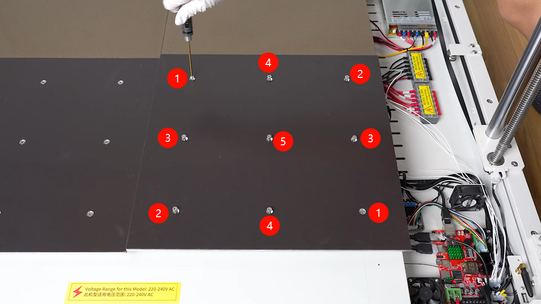
¶ Remove the Heated Bed
Use a 2.5 mm Allen key to gradually loosen the 9 screws in a diagonal sequence over several passes. After confirming that the stress on the heated bed has been released, remove the screws one by one.
.png)
Lift the heated bed from the rear side. When placing it down, avoid pulling the wire harness under the heated bed. If necessary, place a soft cloth under the heated bed to prevent scratching the platform, then remove the 9 springs from the bottom of the heated bed.
.png)
.png)
Use the same method to loosen and remove the right heated bed assembly.
.png)
.png)
¶ Disconnect the Left Z-Endstop Connector
Unplug the left Z-endstop connector.
.png)
.png)
¶ Disconnect the Left Z-Motor Connector
Unplug the left Z-motor connector.
.png)
.png)
¶ Pull Out the Cables
Remove the old Z-endstop cable and Z-motor cable along the cable channel.
.png)
¶ Install the Left Z-Motor Cable and Z-Endstop Cable (Z- and Z1)
¶ Route the Cables
Route the left Z-motor cable and Z-endstop cable from the right side of the cable channel to the left side.
.png)
¶ Connect the Left Z-Endstop Connector
Connect both ends of the left Z-endstop cable to the mainboard and the left Z-endstop switch.
.png)
.png)
¶ Connect the Left Z-Motor Connector
Connect both ends of the left Z-motor cable to the left Z motor and the mainboard.
.png)
.png)
¶ Install the Heated Bed
Place the 9 springs into their installation positions, then place the heated bed assembly into position.
.png)
.png)
Place the 9 heated bed mounting screws into their installation positions. Use a 2.5 mm Allen key to pre-tighten the 9 screws in a diagonal sequence to approximately half of their travel, then adjust them gradually until the heated bed height is basically level with the rear heated bed.
.png)
Then slightly tighten the 9 heated bed mounting screws until the heated bed is approximately level with the rear heated bed.
.png)
Use the same method to install the right heated bed assembly.
.png)
.png)
Install the 2 PEI build plates back onto the heated beds.
.png)
Inside the heated bed power box, use cable ties to secure the cables.
.png)
Inside the mainboard box, use cable ties to secure the cables.
.png)
¶ Install the Power Box Cover and PEI Build Plate Retaining Block
Prepare the power box cover and insert its inner side under the heated bed. Align the screw holes, then slide the power box cover into the installation position.
Use a 2.0 mm Allen key to tighten the 8 screws securing the heated bed power box cover.
The long screws are used at the front and rear sides. The short screws are used on the left side.
Align the screw holes and place the PEI build plate retaining block into the installation position. Use a 2.0 mm Allen key to tighten the 2 screws securing the PEI build plate retaining block.
¶ Install the Mainboard Box Cover and PEI Build Plate Retaining Block
Prepare the mainboard box cover and insert the inner side of the cover under the heated bed.
.png)
Organize the cables connected to the chassis adapter board. Do not leave any cables under the mainboard box cover.
.png)
.png)
Align the screw holes, then slide the mainboard box cover into the installation position.
.png)
Organize the Z-axis motor cables and endstop cables to prevent them from being pinched by the cover.
.png)
.png)
Use a 2.0 mm Allen key to tighten the 8 screws securing the mainboard box cover.
The long screws are used at the front and rear sides. The short screws are used on the right side.
.png)
.png)
.png)
According to the cable labels, connect the connectors to the chassis adapter board one by one.
.png)
Align the screw holes and place the PEI build plate retaining block into the installation position. Use a 2.0 mm Allen key to tighten the 4 screws securing the PEI build plate retaining block.
.png)
.png)
¶ Verification
- Connect the power cable and turn on the printer power switch.
- Check Z-axis up/down movement, Z-endstop triggering, installation of all four PEI build plates, and confirm that no wire harness is pinched before performing auto leveling.
¶ Heated Bed Leveling
¶ 1. Install the Leveling Plates
Replace the 2 front PEI build plates with leveling plates.
The holes on the leveling plates correspond to the screw holes on each heated bed plate.
.png)
.png)
¶ 2. Enter Platform Measurement
Turn on the printer. On the touchscreen, tap Settings > Advanced Settings > Platform Measurement.
.png)
.png)
¶ 3. Start Measuring the Front Heated Beds
After entering the Platform Measurement screen, the printer will start homing. Tap Auto Measure, and the printer will begin measuring the height values of the front heated beds.
Do not perform any other operation during measurement.
.png)
¶ 4. Confirm the Measurement Result
After the measurement is complete, tap Confirm.
.png)
¶ 5. Adjust the Screw Heights
According to the displayed 18-point data, manually adjust the screw height for any point higher or lower than 0.00.
After adjustment, you can manually select the corresponding position number to recheck the value. Adjust the value until it is close to 0.00.
Rotating the screw clockwise by one full turn lowers the platform by 0.7 mm. Rotating it counterclockwise raises the platform by 0.7 mm.
{.is-warning}
.png)
¶ 6. Swap the Leveling Plates and PEI Build Plates
Swap the 2 front leveling plates with the 2 rear PEI build plates.
.png)
¶ 7. Continue Measuring the Rear Heated Beds
Tap Continue Measurement and wait for the print head to measure the height values of the rear heated beds one by one.
.png)
.png)
¶ 8. Adjust the Rear Leveling Plate Points
Use the same method to manually adjust the points on the 2 rear leveling plates.
.png)
¶ 9. Raise the Z Axis
After completing the relative height adjustment of all four heated bed plates, tap Back > Prepare > 50 mm > Raise Z Axis on the touchscreen.
.png)
.png)
¶ 10. Reinstall the Rear PEI Build Plates
After the Z axis rises, replace the 2 rear leveling plates with PEI build plates.
.png)
¶ 11. Start Auto Leveling
Tap Leveling > Confirm > Auto Leveling.
.png)
¶ 12. Wait for the Print Head to Return to Home
Wait for the print head to return to the home position.
.png)
¶ 13. Collect the 100-Point Bed Mesh Data
After the nozzle and heated bed finish heating, the printer will automatically collect data from 100 points on the heated bed.
.png)
¶ 14. Adjust the Z-Offset
After data collection is complete, place a sheet of A4 paper between the nozzle and the platform, then adjust the compensation value. The setting is complete when there is noticeable resistance while pulling the A4 paper.
.png)
¶ 15. Save the Data
Tap Confirm > Save Data.
.png)
.png)
¶ 16. Finish
Return to the home screen. The printer is now ready for normal use.
.png)
.png)