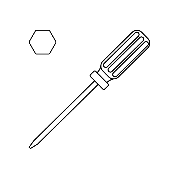
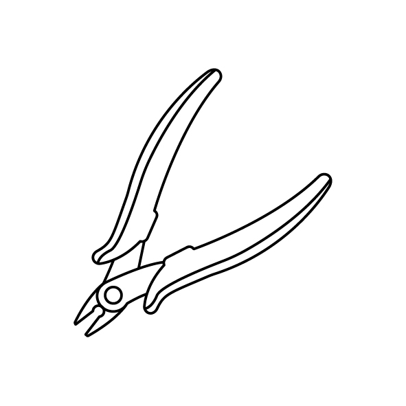
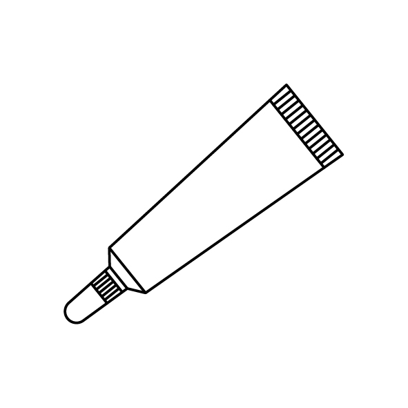
¶ Tools and Materials
- A 2.0 mm Allen wrench
- A pair of needle-nose pliers
- Thermal silicon grease
- New thermistor and new ceramic heating plate
¶ Tutorial Video
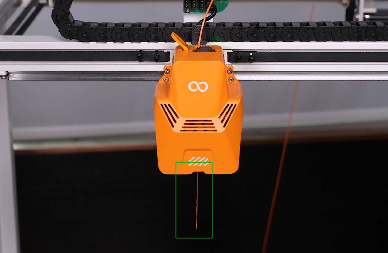
¶ Instruction
- Power off the printer and unplug the power cord.
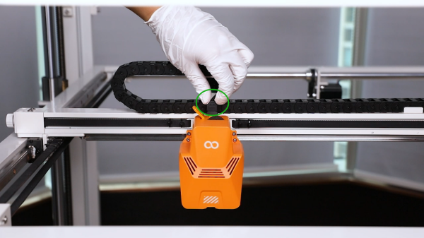
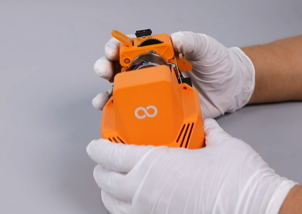
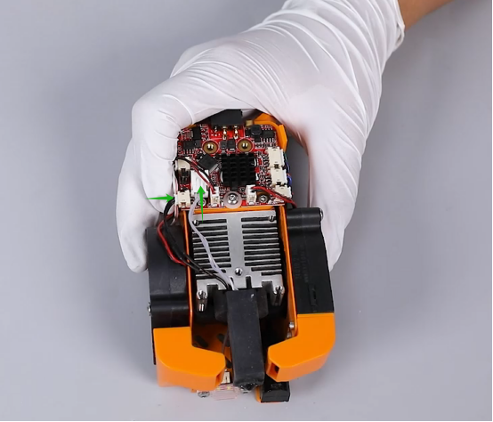
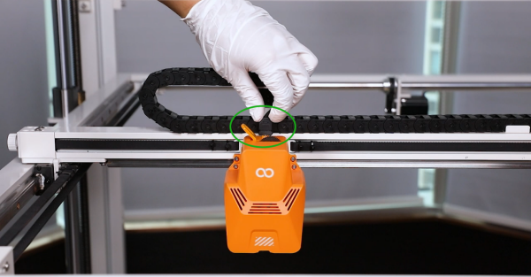
- Unplug the ribbon cables above the printing head.
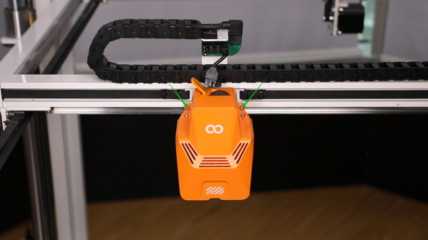
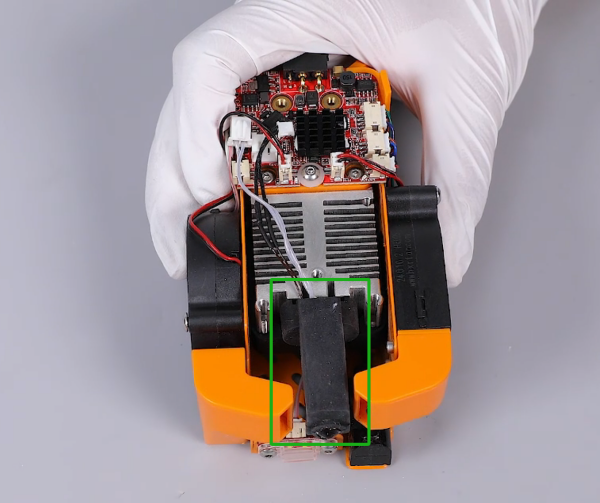
- Loosen the 2 screws securing the rear of the printing head using a 2.0 mm Allen wrench.
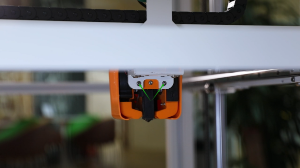
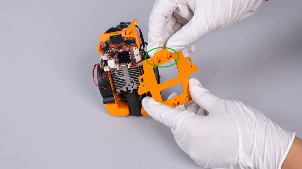
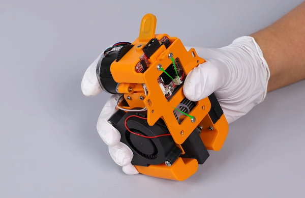
- Loosen the 2 screws securing the front of the printing head using a 2.0 mm Allen wrench and remove the entire printing head.
Note: Holding the printing head while loosening the last screw to prevent it from falling.
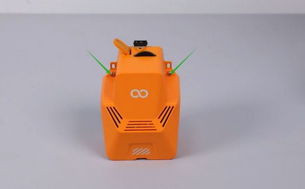
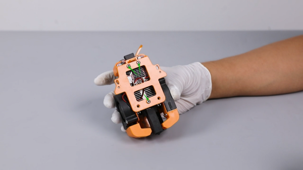
- Loosen the 2 screws securing the front cover of the printing head using a 2.0 mm Allen wrench and remove the front cover.
- Loosen the 3 screws securing the back plate of the print head using a 2.0 mm Allen wrench and remove the back plate and the pressing plate of the adapter board.
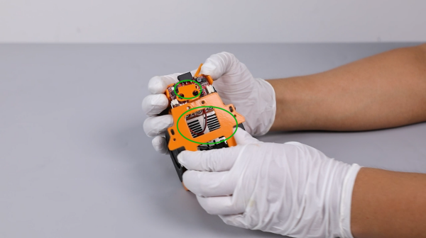
- Unplug the ribbon cables from the thermistor and the port of ceramic heating plate.

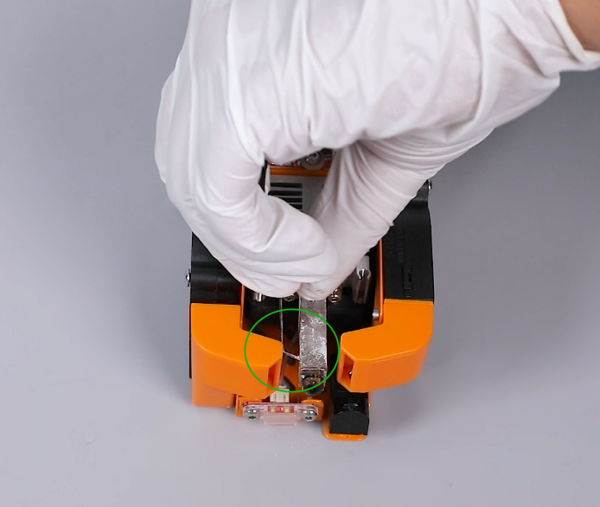
- Remove the black silicone sleeve.
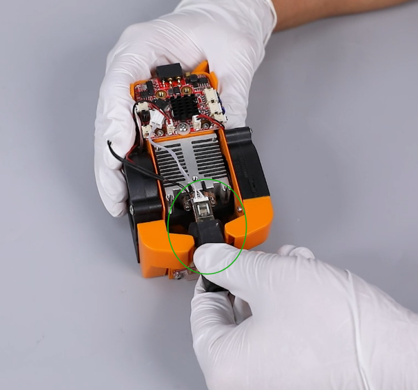
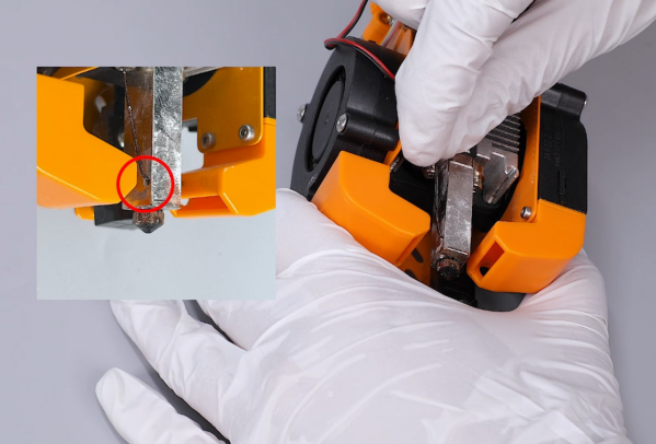
- Use a pair of needle-nose pliers to remove the two heating plate clip rings.
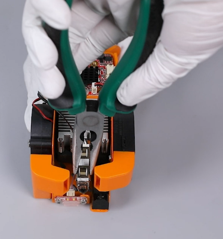
- Note: Apply gentle pressure to prevent damaging the ceramic heater.
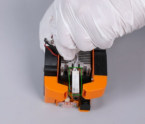
- Remove the old thermistor and the old ceramic heating plate.
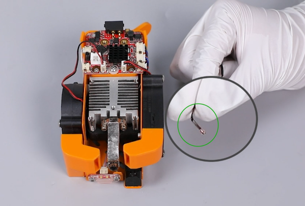
- Prepare the new thermistor. Bend the ribbon cable of the thermistor about 5 mm in front of it.
- Put the thermistor in the installation position by aligning it with the hole of it.
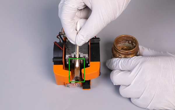
- Apply thermal paste evenly on the surface of the heating block where the heating plate is installed.
- Prepare the new ceramic heating plate. Put it in the installation position by aligning it with the heating block.
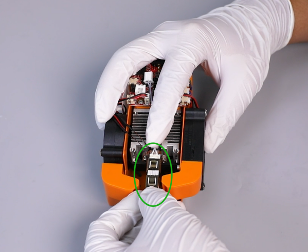
- Install the clip ring of the heating plate.
Note: Pay attention to the direction of the clip ring.
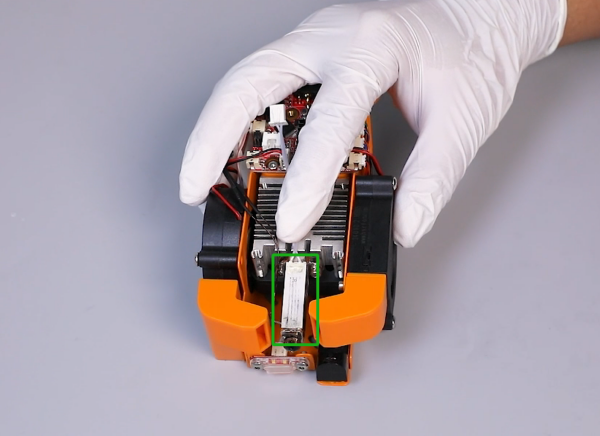
- Install the black silicone sleeve.
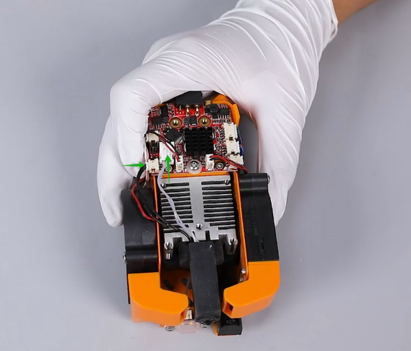
- Plug the ribbon cables of thermistor and the ceramic heating plate into the TH1 and HE0 ports on the adapter board of the printing head.
- Prepare the back plate of the printing head pressing plate of the adapter board. Attach pressing plate of the adapter board to the screw holes on the back plate of the printing head.
Note: The pressing plate of the adapter board has the fixed installation direction.
- Put the back plate of the printing heat in installation position by aligning it with the screw holes and tighten the 3 securing screws using a 2.0 mm Allen wrench.

- Put the front cover in the installation position by aligning it with the screw holes and tighten the2 securing screws using a 2.0 mm Allen wrench.

- Put the entire printing head in the installation position by aligning it with the screw holes. Tighten the 2 securing screws using a 2.0 mm Allen wrench.
Note: Align the level of the screw holes of the printing head’s two side with the level of the mounting bracket of the printing head.
- Tighten the two screws securing the rear of the printing head using a 2.0 mm Allen wrench.

- Plug in the ribbon cables above the printing head.
- Power on the printer.
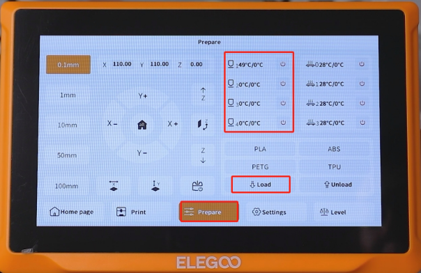
- Touch "Prepare" and set the nozzle temperature to 220 °C. After reaching the temperature, touch "Load" on the touchscreen.
- Observe the nozzle can work normally. Re-level the printer and the printer can be used as usual.