¶ Tools and Materials
- 2.5mm Allen key x 1
- 2.0mm Allen key x 1
- A Phillips screwdriver
- A pair of diagonal pliers
- Cable ties
¶ Tutorial Video
Coming soon.
¶ Instruction
¶ Remove the old heated bed assembly
- Power off the printer and unplug the power cord.
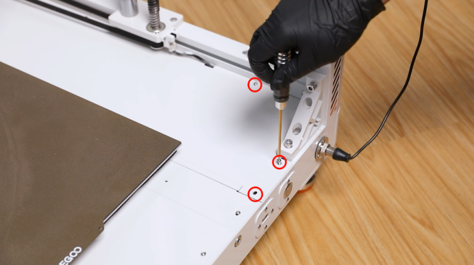
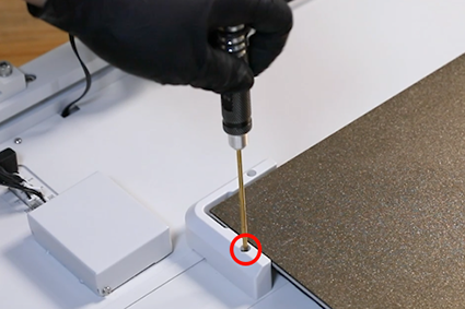
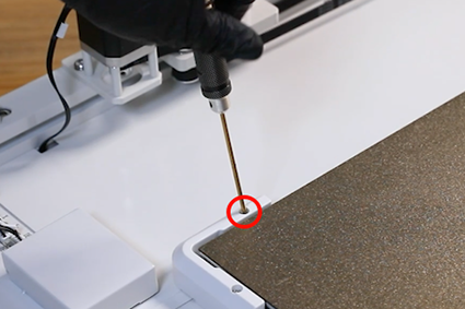
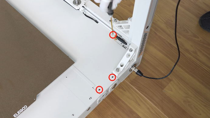
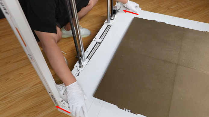
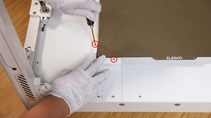
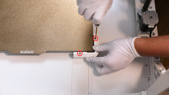
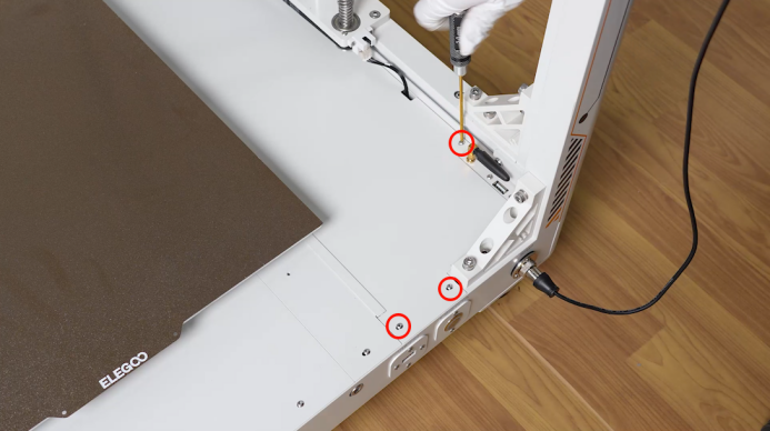
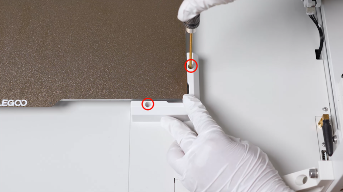
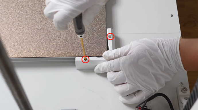
- Using the 2.0mm Allen key, remove the two screws securing the front and back PEI limiters at the right side of the printer. Remove the PEI limiters.
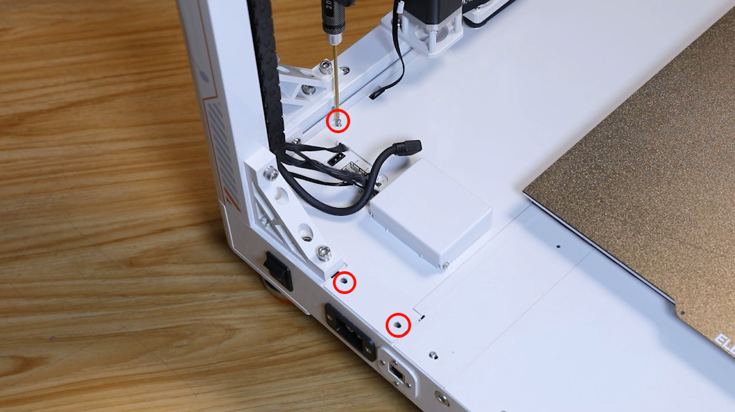
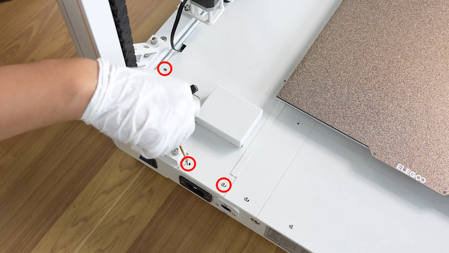
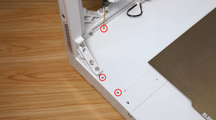
- Using a 2.0 mm Allen key, remove the eight screws securing the power box cover .
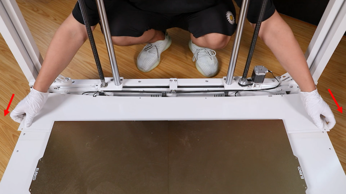
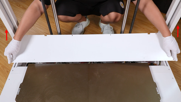
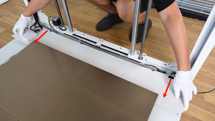
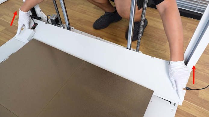
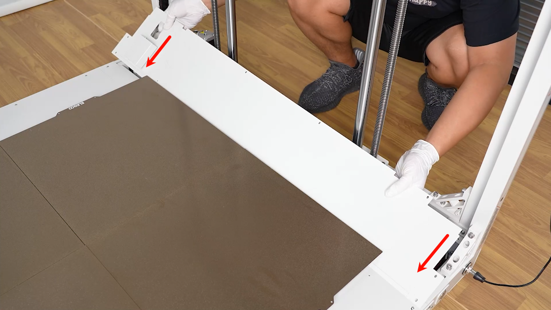
- Push the power box cover of the heated bed towards the heated bed. Lift the outer side of the cover and remove it.
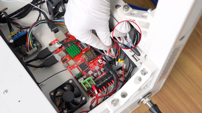
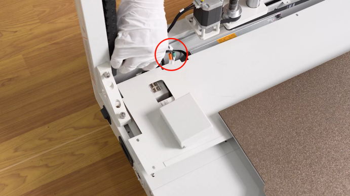
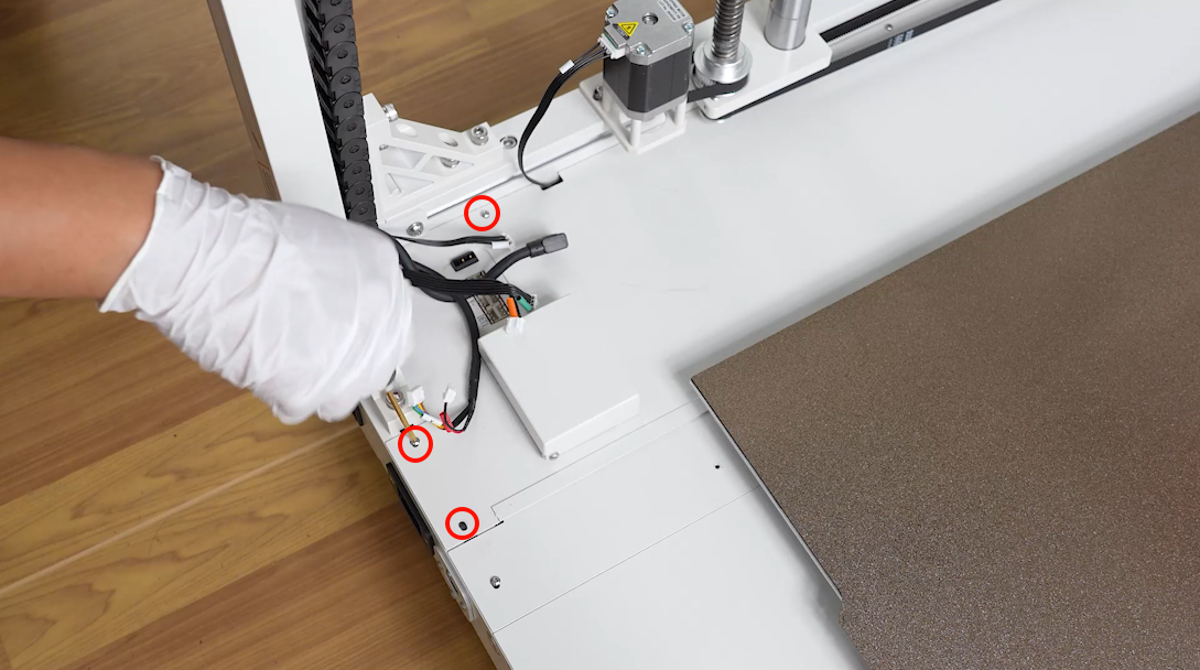
- Unplug the cables on the adapter board at the right back side of the printer.
- Using the 2.0mm Allen key, remove the two screws securing the front and back PEI limiters at the right side of the printer. Remove the PEI limiters.
- Using a 2.0 mm Allen key, remove the eight screws securing the motherboard box cover .
- Push the power motherboard box cover towards the heated bed. Lift the outer side of the cover and remove it.
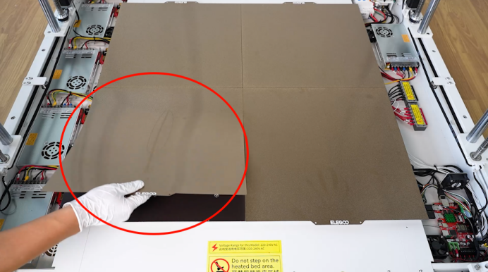
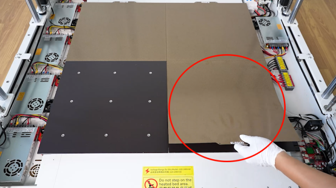
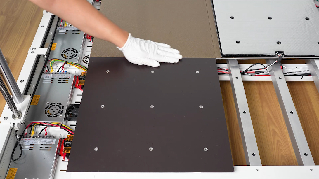
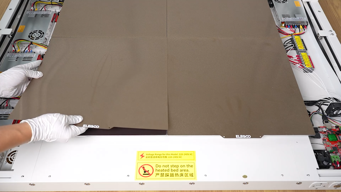
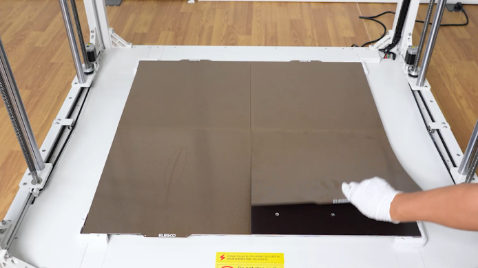
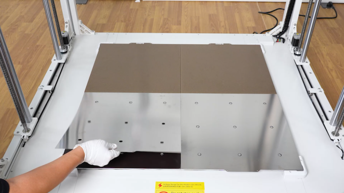
- Remove the PEI plates of the two heated bed on the front side.
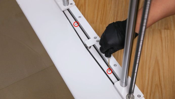
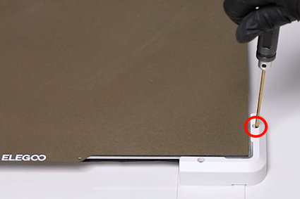
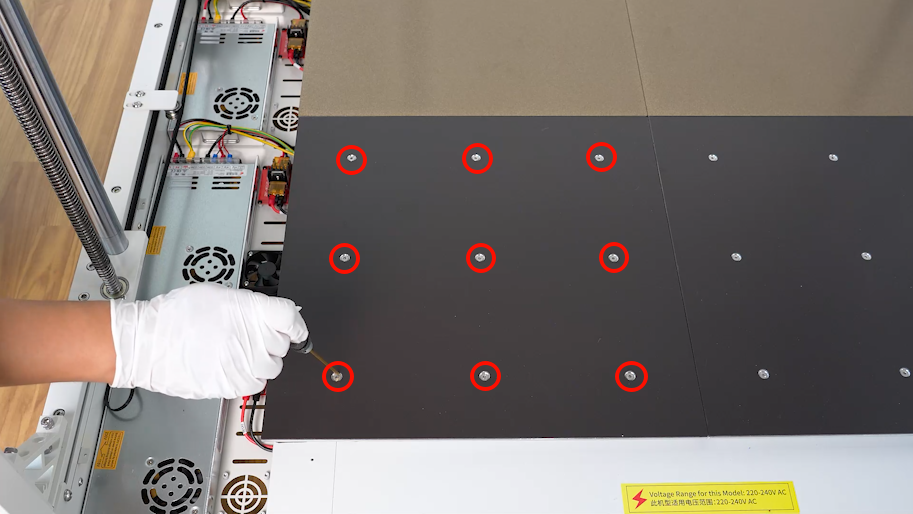
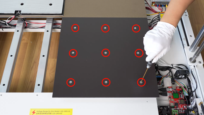
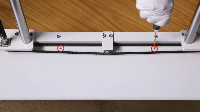
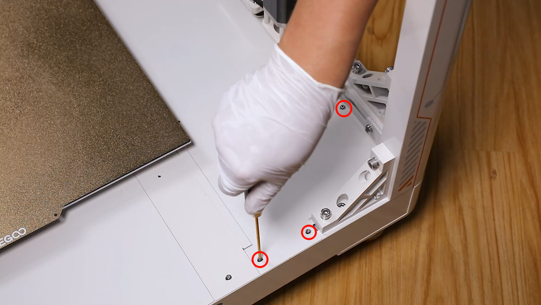
- Using a 2.5mm Allen key, loosen the nine screws securing the heated bed. And remove the screws.
NOTE: Do not remove the screws at once.
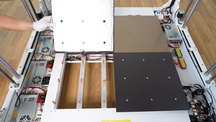
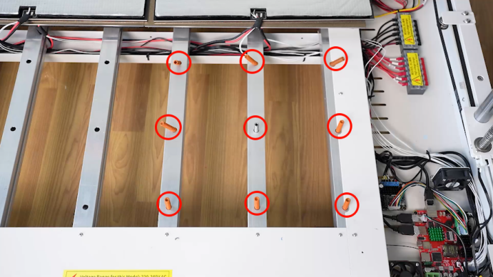
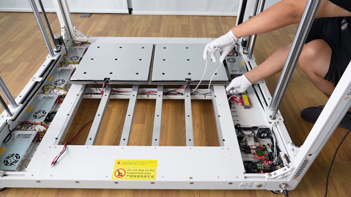
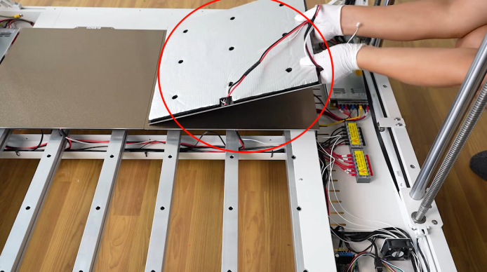
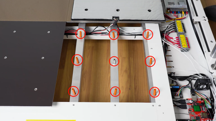
- Lift the heat bed and put it on the heated bed on the rear side. Remove the nine springs under the heated bed.
Note: There are cables under the heated bed. Take care to remove it.

- Remove the heated bed assembly on the right side in the same way.
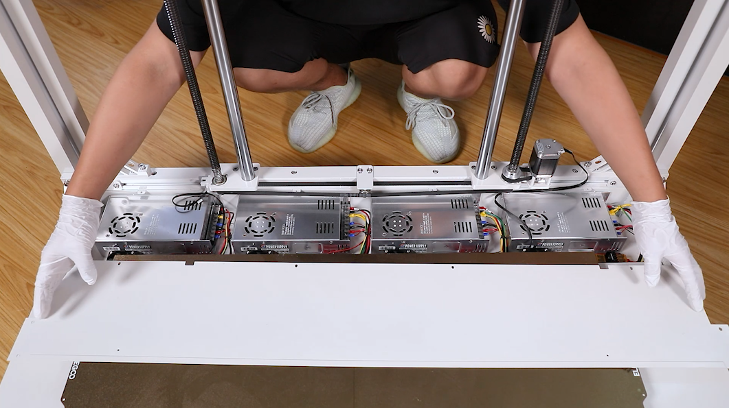
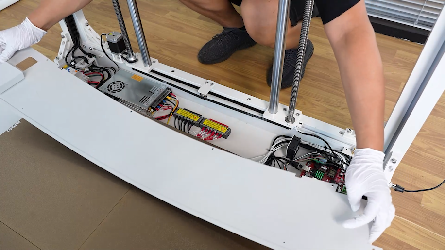
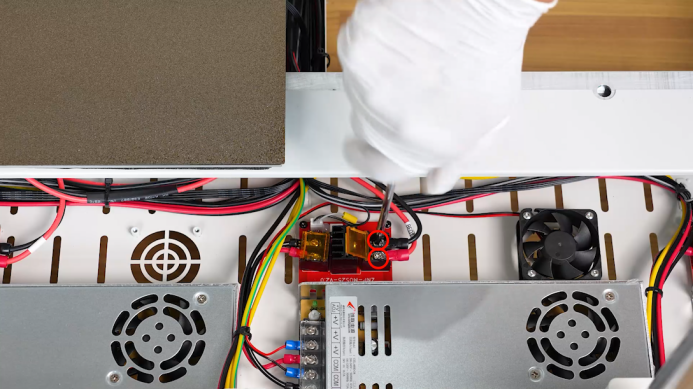
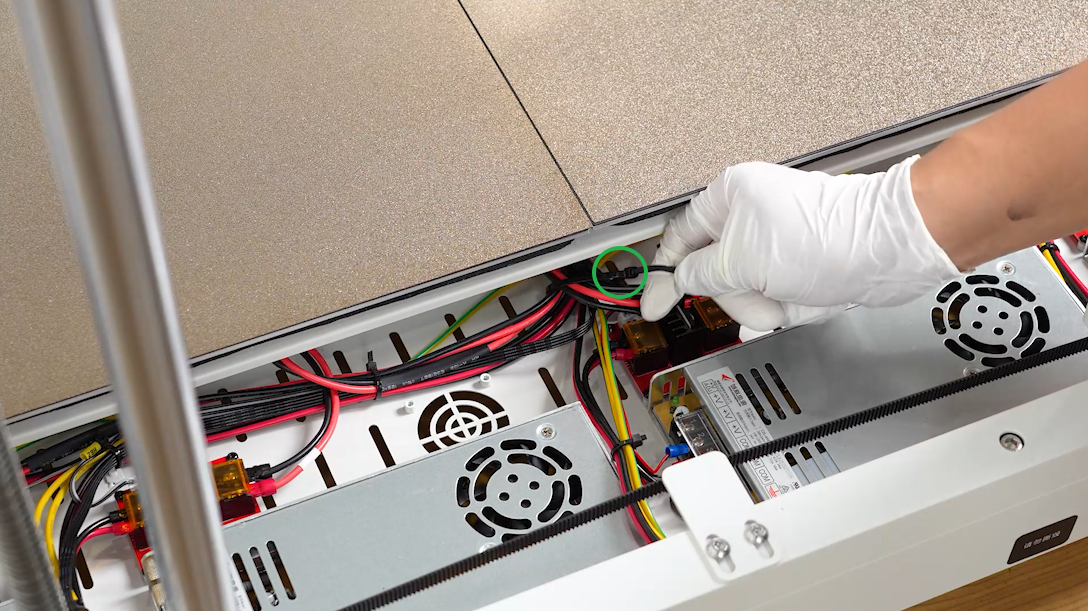
- In the power box, cut off the cable ties securing the connection cables of the heated bed using a pair of diagonal pliers.
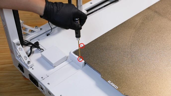
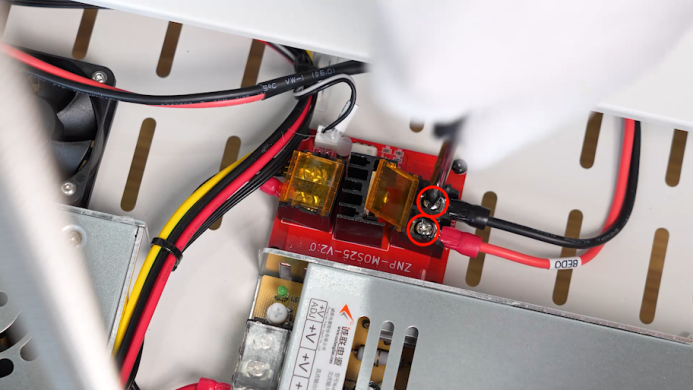
- Using a Phillips screwdriver, loosen the two screws securing heated bed connection cables on the MOS board on the motherboard. Organize and pull out the connection cables of the left-side heated bed.
NOTE: It is easier to find the connection cables from the bottom of the heated bed.
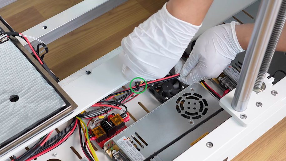
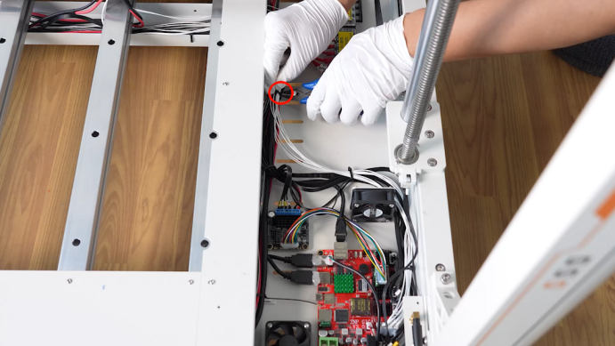
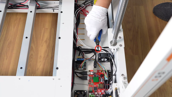
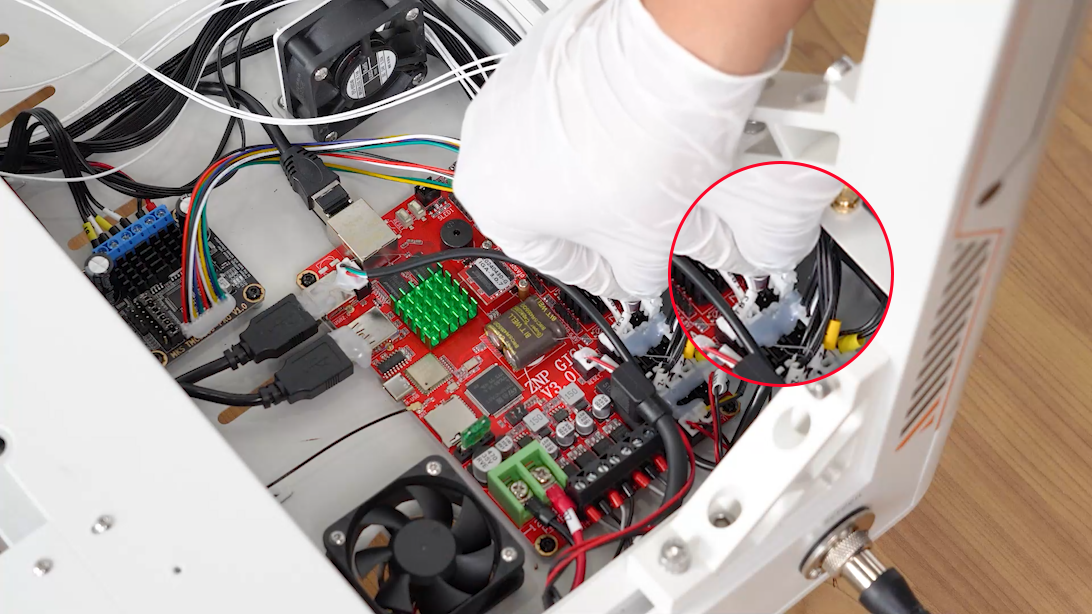
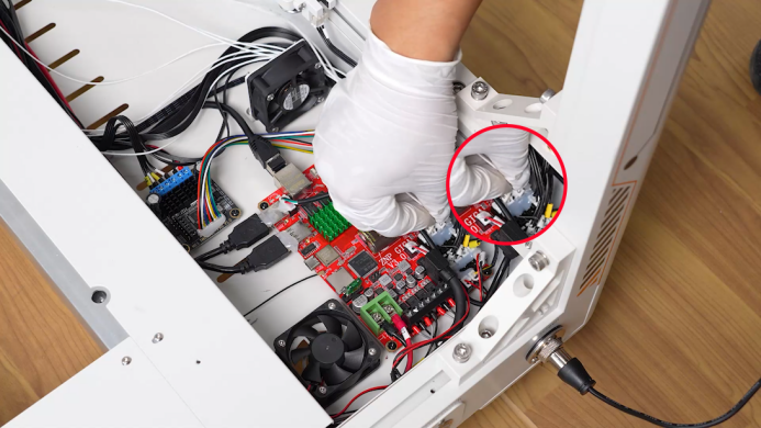
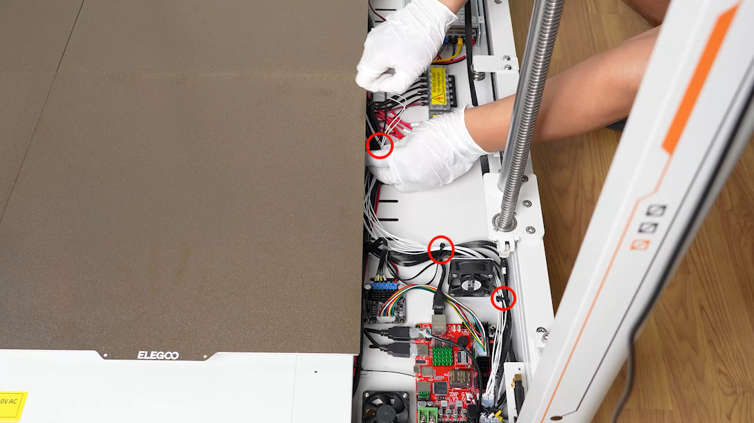
- In the motherboard box, using a pair of diagonal pliers, cut off the three cable ties securing the thermistor of the heated bed. Unplug the cable port of the thermistor of the heated bed.
NOTE: It is easier to find the connection cables from the bottom of the heated bed.
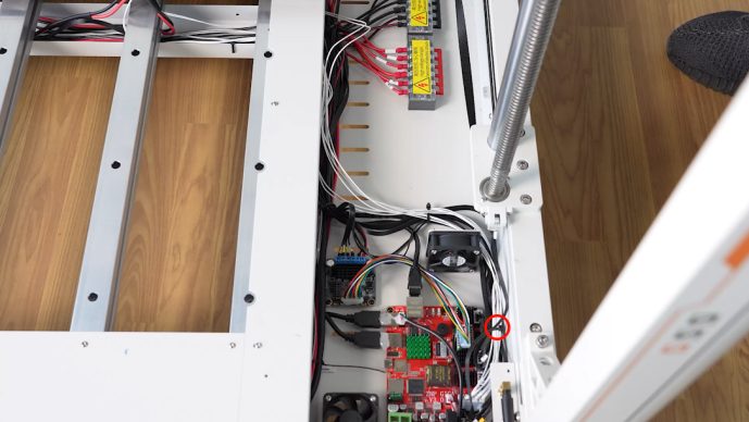
- Organize and pull out the cables of the thermistor of the heated bed on the right side. And remove the left-side heated bed assembly.
- Organize and pull out the connection cables of the heated bed on the right side in the same way. Remove the heated bed assembly.
¶ Install the new heated bed assembly
¶ Install the heated bed assembly
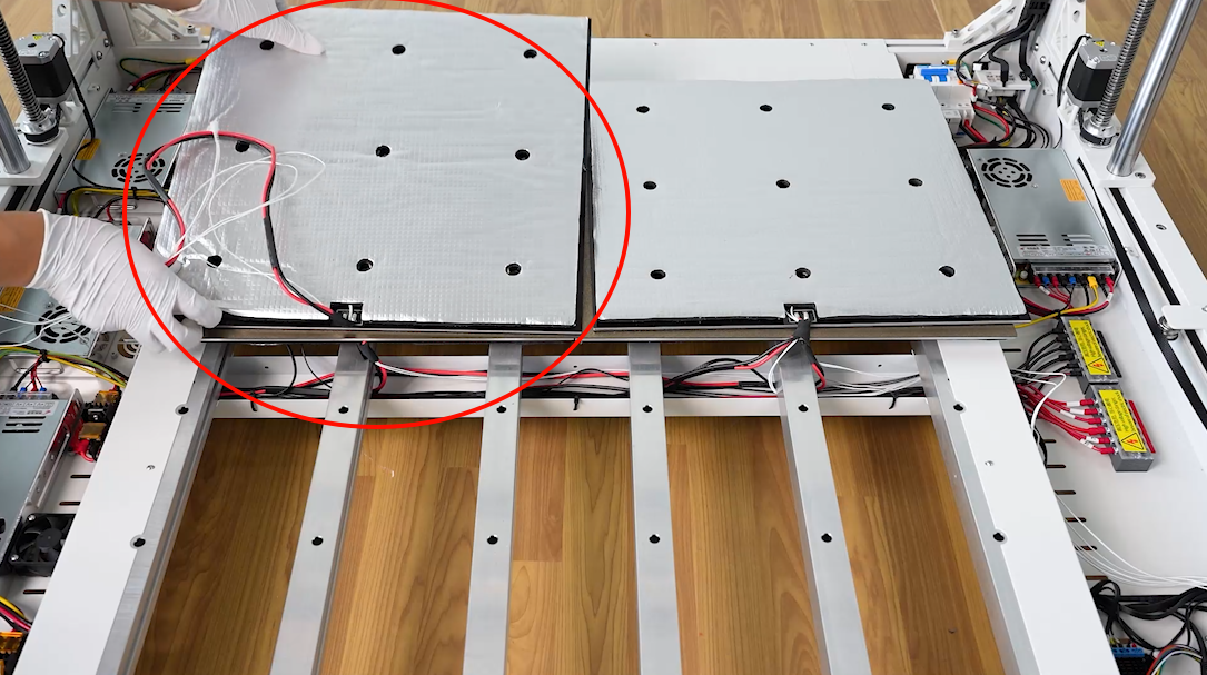
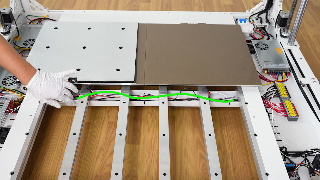
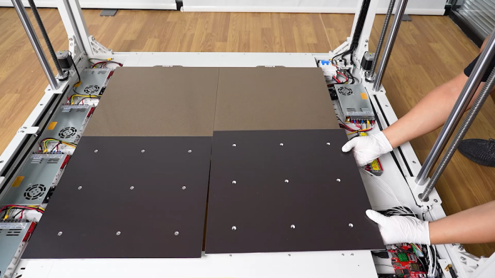
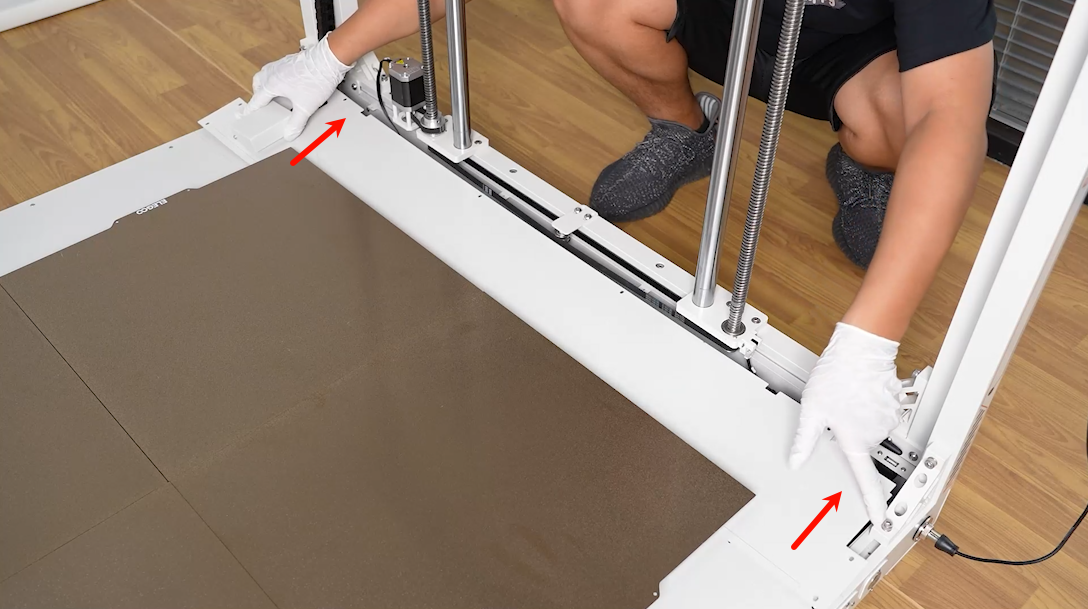
- Prepare the new heated bed assembly. Put it on the heated bed on the rear side.
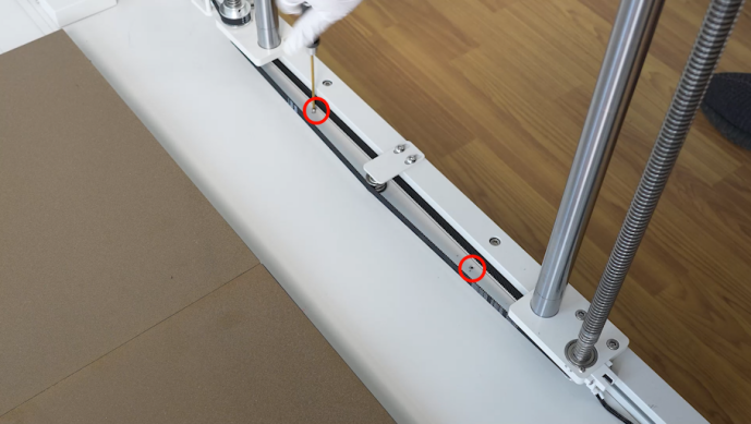
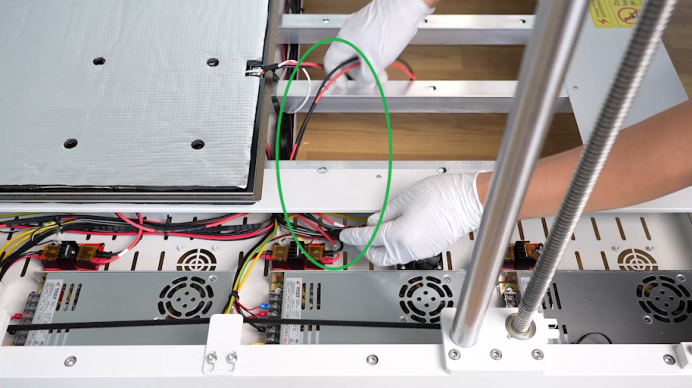
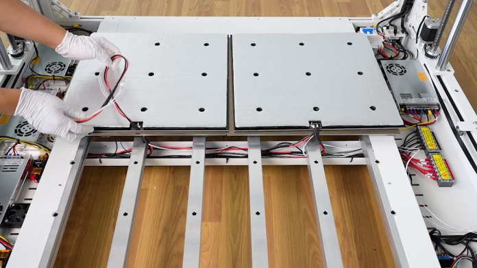
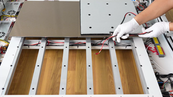
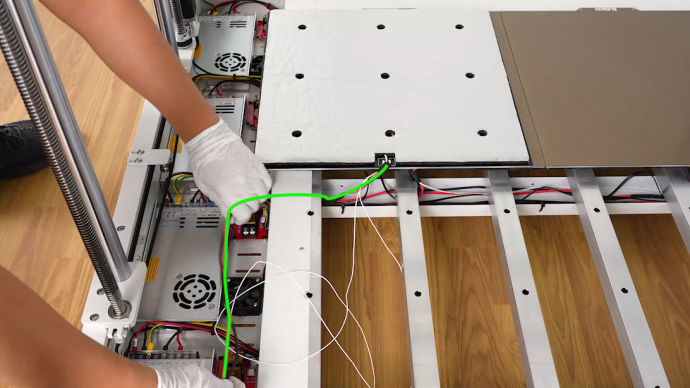
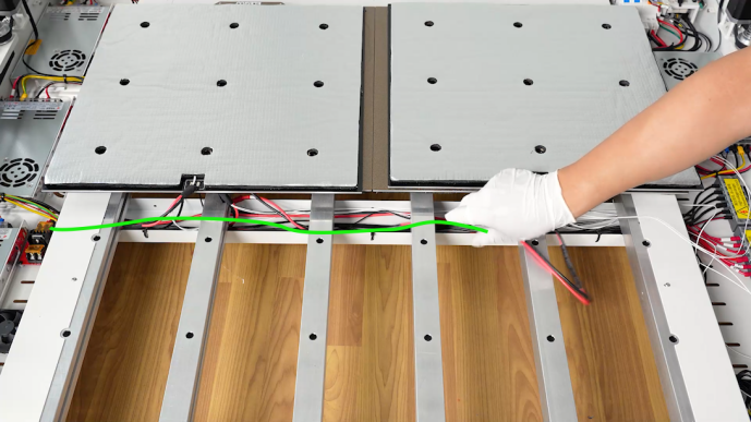
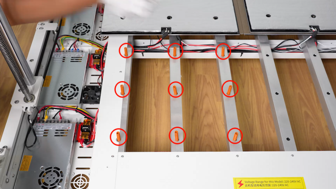
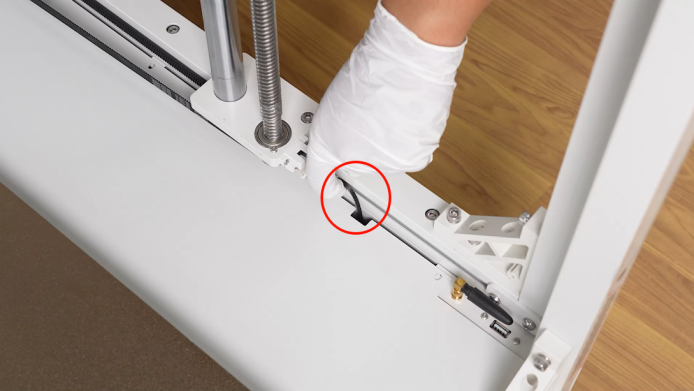
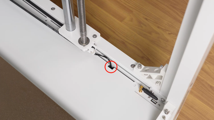
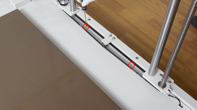
- Organize the cables. Pass the connection cables of the heated bed through the hole in the aluminum profile at the bottom of the printer and Insert the cables into the power box of the heated bed.
NOTE: The cables for the front and back heated beds should be routed along opposite sides of the aluminum profile.
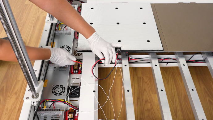
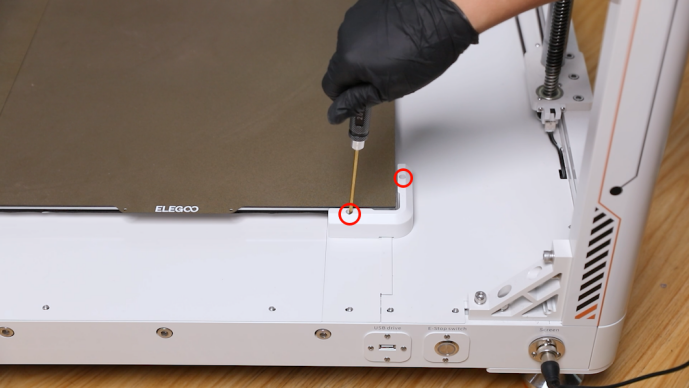
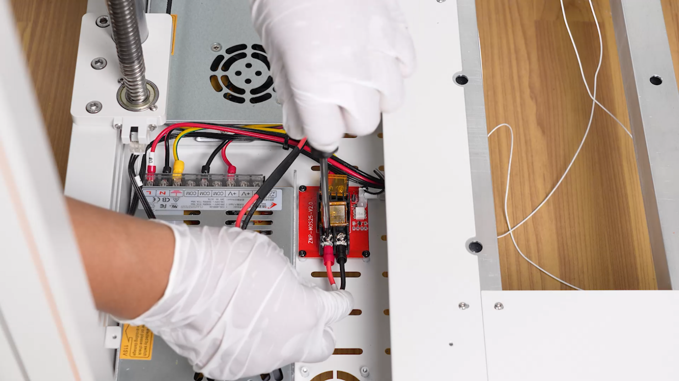
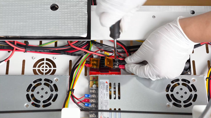
- Connect the red connection cable with the positive connector and the black connection with negative connector. Using a Phillips screwdriver, secure the two screws holding the heated bed connection cable. Cover the plate and organize the heated bed connection cables.
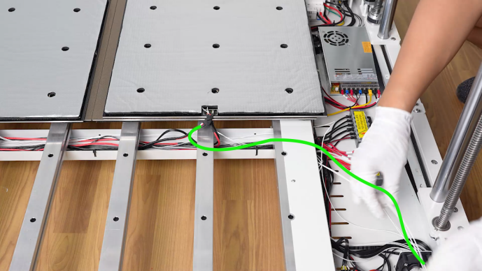
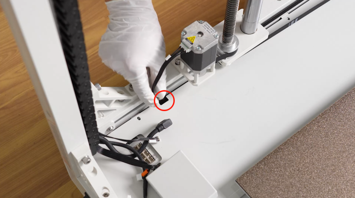
- Pass the connection cables of the heated bed thermistor through the hole in the aluminum profile at the bottom of the printer. Insert the cables into the motherboard box.
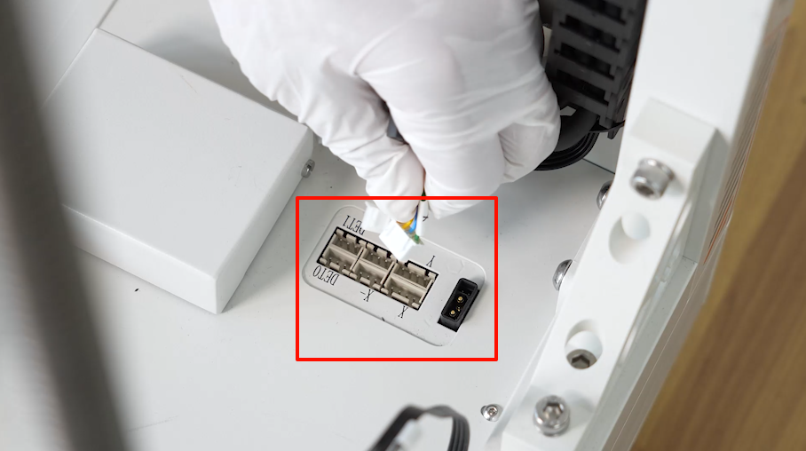
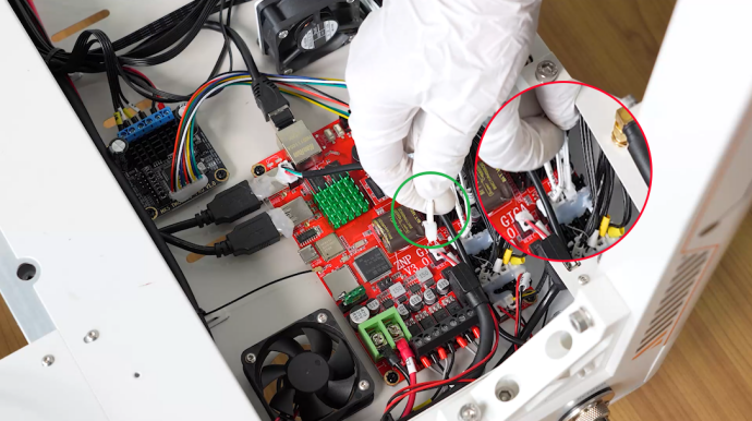
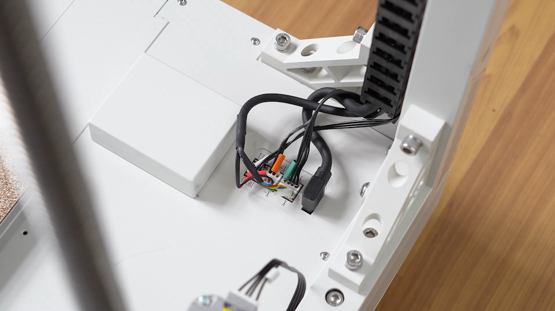
- Insert the cables of the heated bed thermistor on the left front side into the TB0 port on the motherboard.
- Organize and insert the connection cables of the heated bed on the right side in the same way.
- Insert the cables of the heated bed thermistor on the right front side into the TB1 port on the motherboard.
- Align the nine springs with the screw holes. Align the heated bed assembly with the springs and put it in the installation position.
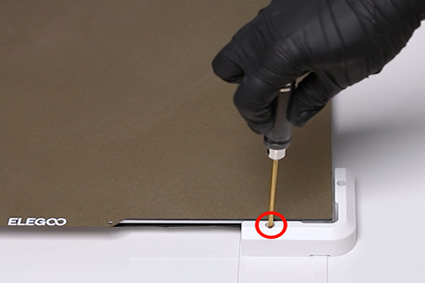
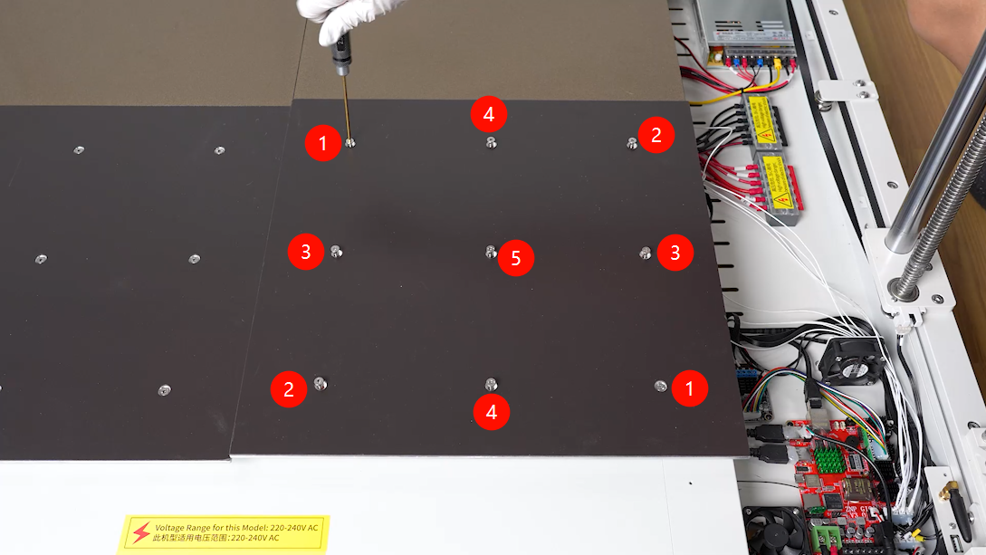
- Align the nine screws securing the heated bed with the screw holes and put them in the installation position. Using a 2.5mm Allen key, diagonally turn the nine screws securing the heated bed to half of its depth.
NOTE: Do not tighten the screws at once.
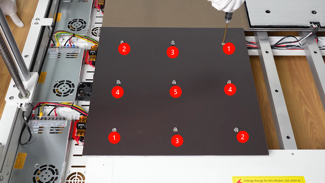
- Tighten slightly the nine screws a little bit more until they are approximately flush with the heated bed on the back side.
- Install heated bed assembly on the right side in the same way.
- Install the two PEI build plates to the heated bed.
- In the power box, secure the connection cables of the heated bed using a cable tie.
- In the motherboard box, secure the thermistor cables of the heated bed using three cable ties.
- The other two heated bed assemblies on the back side can be replaced in the same way.
¶ Install the power box cover and PEI limiters
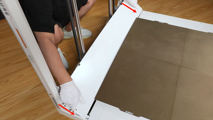
- Prepare the power box cover and put it under the heated bed by placing sideways. Align the power box plate with the screw holes and slide the plate to the installation position.
- Using a 2.0 mm Allen key, tighten the eight screws securing the power box cover .
NOTE: The front and rear sides are fixed with long screws and the left side is fixed with short screws.
- Align the PEI limiters with the screw holes and put them in the installation position. Using the 2.0 mm Allen key, tighten the two screws securing PEI limiters.
¶ Install the motherboard box cover and PEI limiters
- Prepare the motherboard box cover and put it under the heated bed by placing sideways.
- Organize the cables connected to the chamber interface board. Do not leave them under the cover plate.
- Align the power box plate with the screw holes and slide the plate to the installation position.
- Organize the cables of the Z-axis motor and the limit switch to to avoid being pinched by the cover plate.
- Using a 2.0 mm Allen key, tighten the eight screws securing the motherboard box cover.
NOTE: The front and rear sides are fixed with long screws and the right side is fixed with short screws.
- Insert the ribbon cables into the chamber interface board according to the label information.
- Align the PEI limiter with the screw holes and put it in the installation position. Using a 2.0 mm Allen key, tighten the two screws securing the PEI limiter.
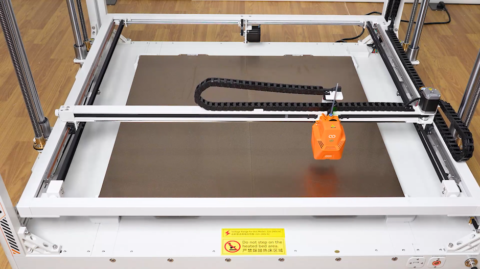
¶ Level the heated bed
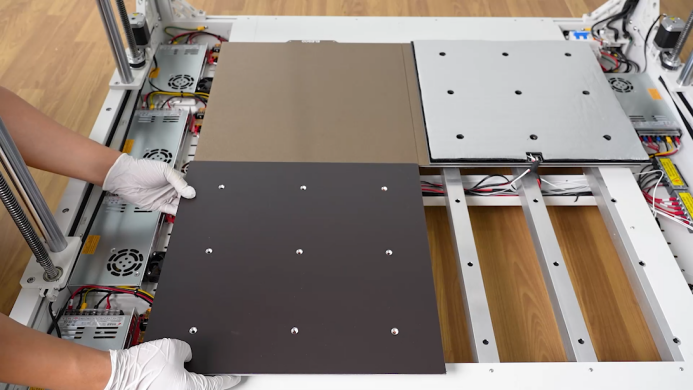
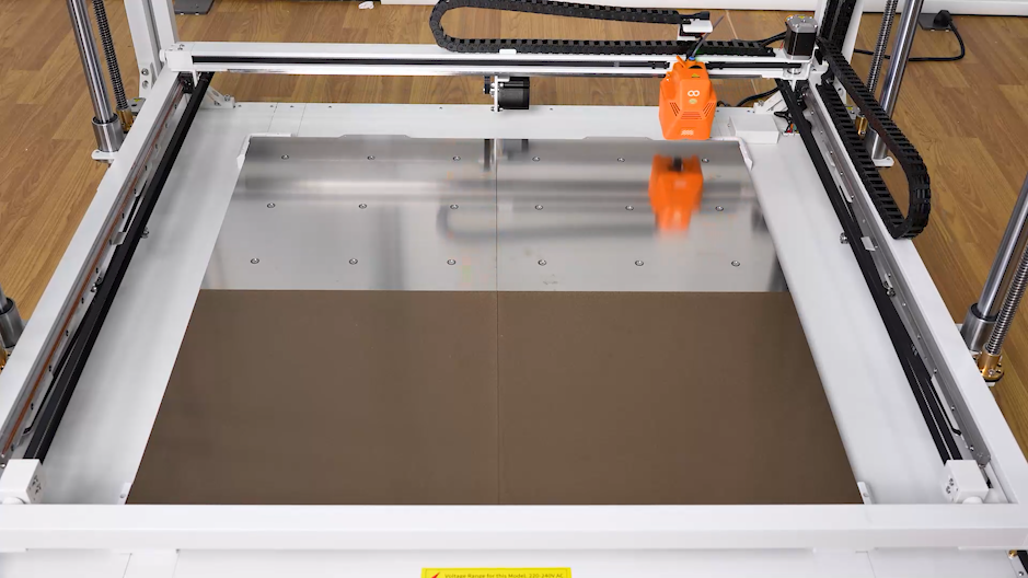
- Replace the two PEI platform boards in the front half with leveling plates.
NOTE: The hole positions on the leveling plate should correspond to each screw hole position on the heated bed.
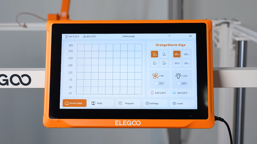
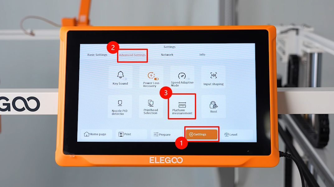
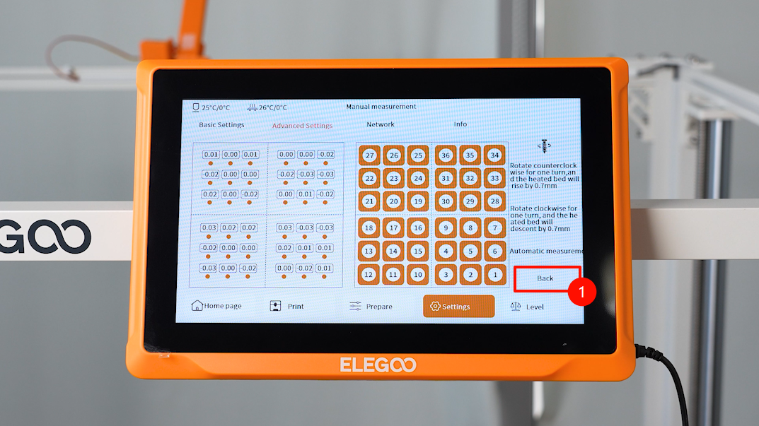
- Power on the printer. Select Setting - Advanced - Measurement on the touchscreen.
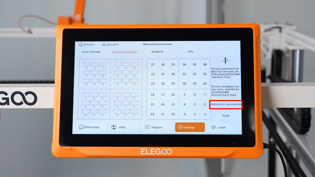
- After entering the measurement interface, the printer starts homing process. Select Automatic Measure and the printer starts measuring the height value of the front half of the heated bed.
NOTE: No other operations can be performed during the measurement.
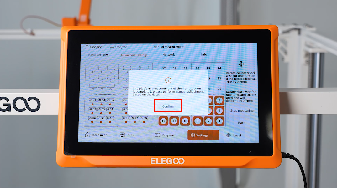
- After the measurement is complete, click Confirm.
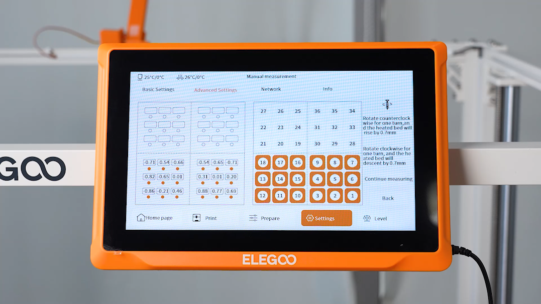
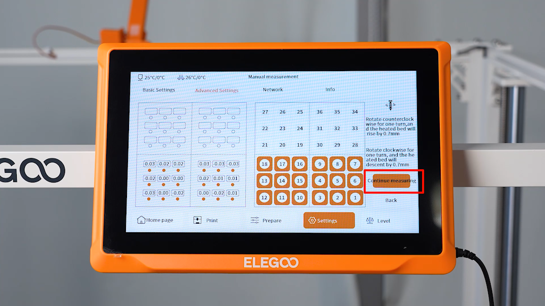
- Observe the value of the 18 points on the touchscreen. Manually adjust the screw height above or below 0.00. After adjustment, select the corresponding point number to recheck the height value. Make sure that the value is close to 0.00.
NOTE: Rotate the screw clockwise by a full turn, the build plate lowers by 0.7mm. Rotate the screw counterclockwise by a full turn, the build plate raises by 0.7mm.
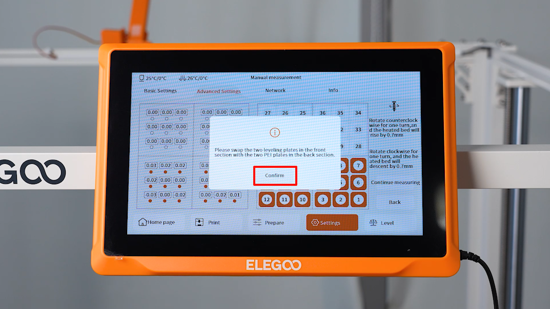
- Swap the two leveling plates of the front half with the two PEI build plates of the back half.
- Click Continue Measurement. Wait for the print head to measure the height values of the latter half of the heated bed sequentially.
- Manually adjust the points of the two leveling plates in the latter half in the same way.
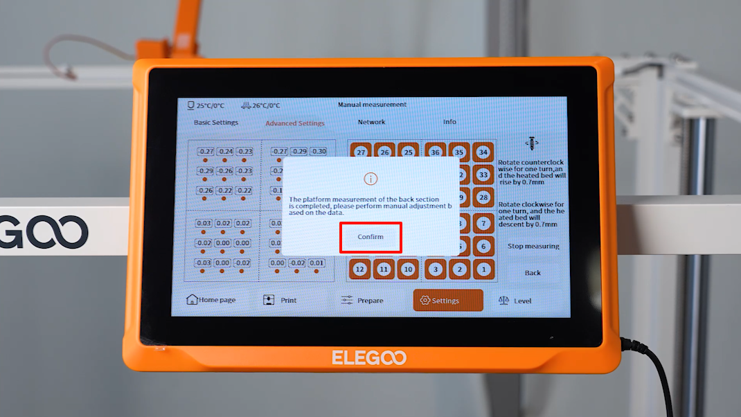
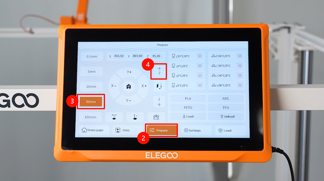
- After the adjustment of the realative height of the four heated bed build plates, click Return - Prepare - 50 mm - Raise the Z-axis on the touchscreen.
- After waiting for the Z-axis to rise, replace the two leveling plates at the back with the PEI build plate board.
- Select Calibrate - Automatic leveling - Confirm on the touchscreen.
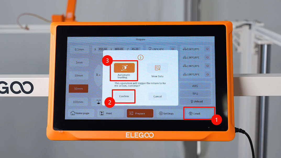
- Wait for the print head to return to the home position.
- After the nozzle and the heated bed are heated up, automatic data collection is conducted at 100 points on the heated bed.
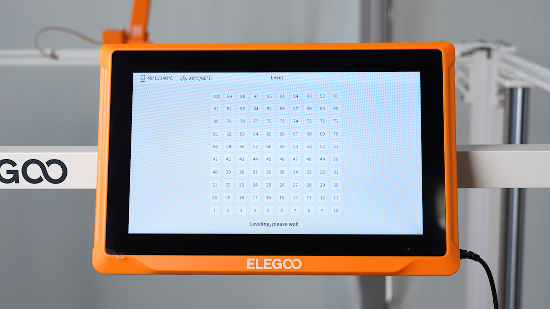
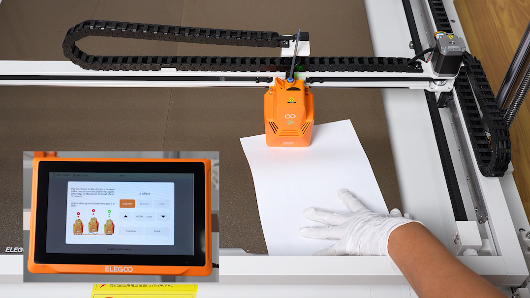
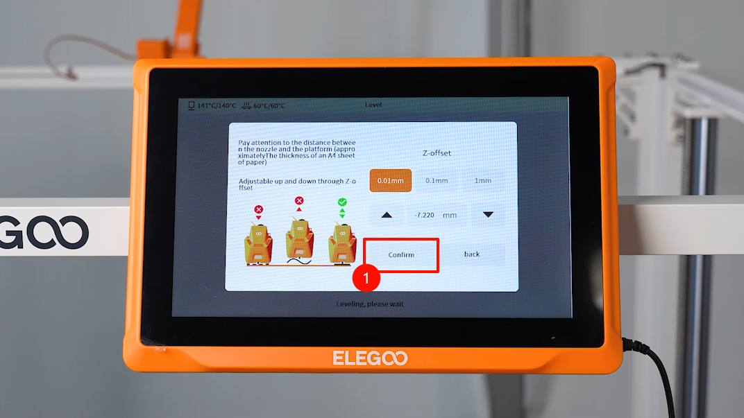
- After the data collection is completed, place an A4 paper between the nozzle and the build plate and adjust the offset value. If there is a noticeable resistance while pushing or pulling A4 paper, the setting is complete.
- Click Confirm - Save.
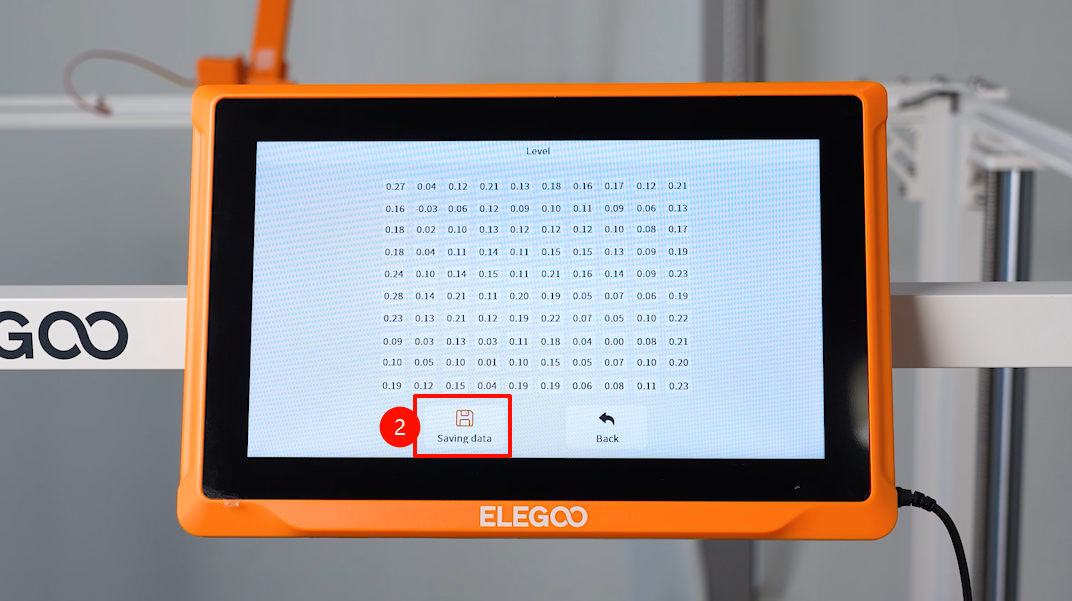
- Click Confirm - Save Data and return to the main interface, the printer is ready for use.