¶ When to replace
When the hotbed can not heat up or the MOS module operates abnormally, it is necessary to replace the hotbed MOS control board.
¶ Tools and Materials
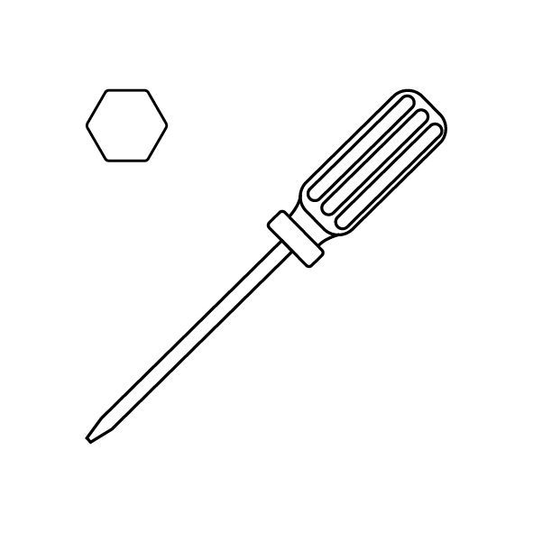
- A 2.0 mm Allen wrench
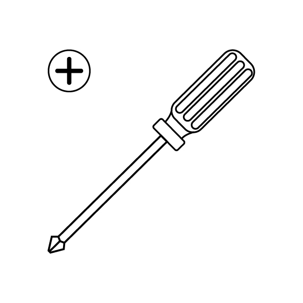
- A Phillips screwdriver
- A new hotbed MOS control board
¶ Reference Video
¶ Instruction
- Power off the printer and unplug the power cord.
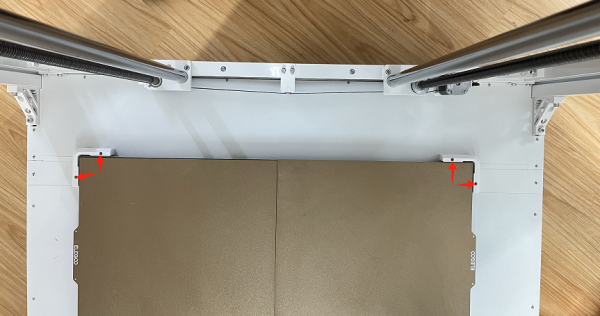
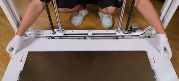
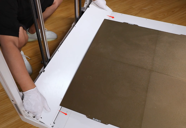
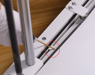
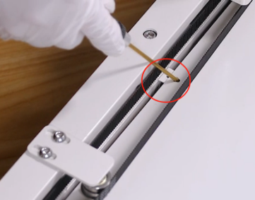
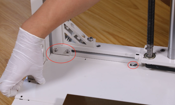
- Loosen the 2 screws securing the PEI limit block on the left front and rear of the printer using a 2.0 mm Allen wrench and remove the PEI limit block.
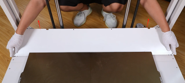
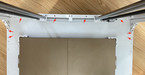
- Loosen the 8 screws securing the hotbed power box cover using a 2.0 mm Allen wrench.

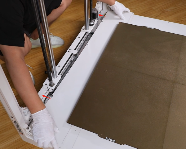
- Remove the hotbed power box cover by sliding it towards the heat bed from below, and then lift the outer side of the power box cover to remove it.
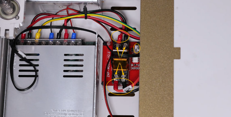
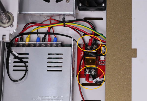
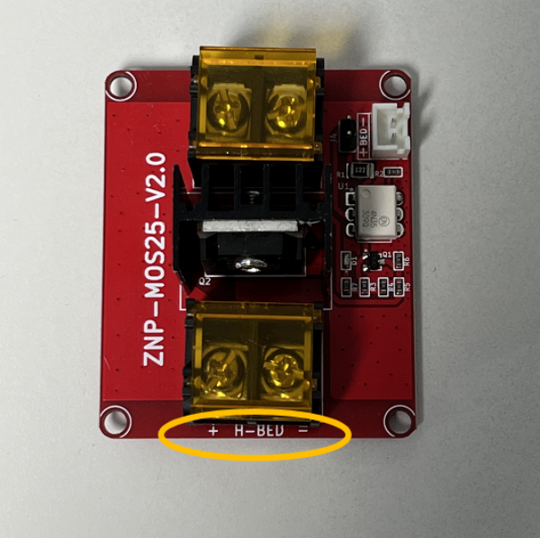
- Loosen the screws at the input terminal and H-BED ribbon cable port on the hotbed MOS control board using a Phillips screwdriver and then remove the ribbon cables.
- Loosen the 4 screws securing the hotbed MOS control board using a 2.0 mm Allen wrench and remove the old hotbed MOS control board.
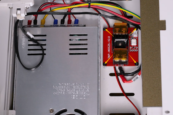
- Prepare the new hotbed MOS control board. Put it in the installation position by aligning it with the screw holes. Tighten the four securing screws using a 2.0 mm Allen wrench.

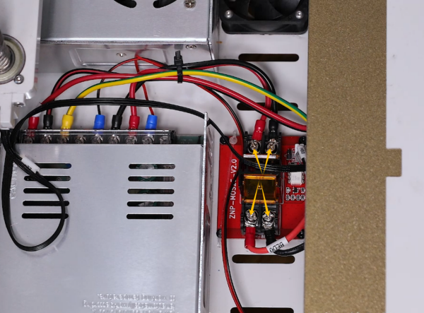
- Plug the cables into the hotbed MOS control board ports according to the labels on the ribbon cables.
Note: Inserting the cables into the input terminal and H-BED port based on the principle of "red positive black negative" .
- Tighten the screws securing the cable ports using a Phillips screwdriver.
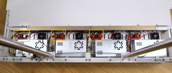
- Replace the other 3 hotbed MOS control boards in the same way.
- Remove the power box cover by sliding the inner side under the heat bed. Slide the power box cover to the installation position by aligning it with the screw holes.
Note: Do not press on the timing belt and motor ribbon cables.
- Tighten the 8 screws securing the hotbed power box cover using a 2.0 mm Allen wrench. (Long screws are fixed on the front and back of the printer and short screws are fixed on the left side of the printer.)
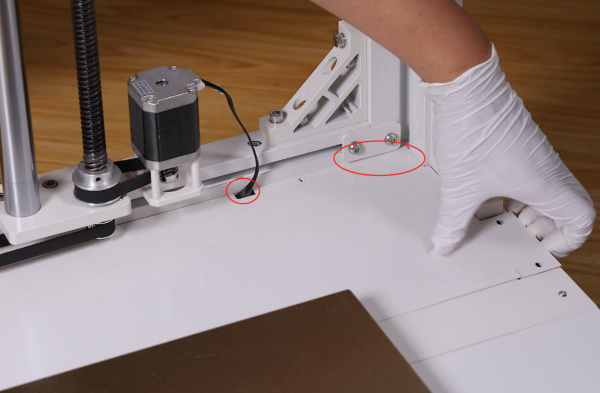
- Put the PEI limit block in the installation position by aligning it with the screw holes, and tighten the 2 securing screws using a 2.0 mm Allen wrench.

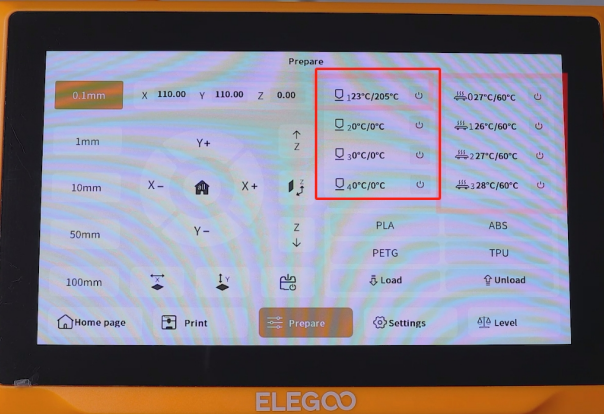
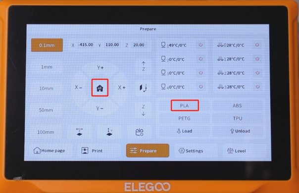
- Plug in the power cord and power on the printer. Touch "Prepare-PLA" on the touchscreen.
- The printer can be used as usual after it can heat normally.