¶ Tools and Materials
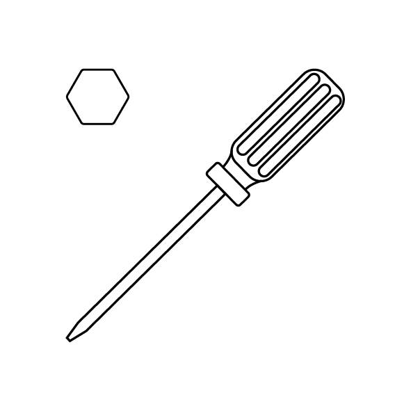
- A 1.5mm Allen wrench
- A 2.0mm Allen wrench
- A new extruder gearbox
¶ Tutorial Video
¶ Operation Steps
- Power off the printer and unplug the power cord.
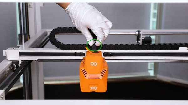
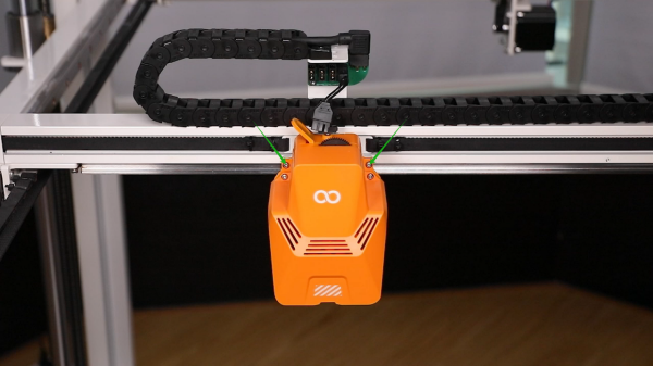
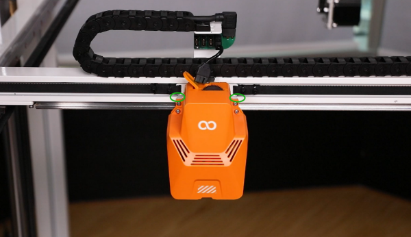
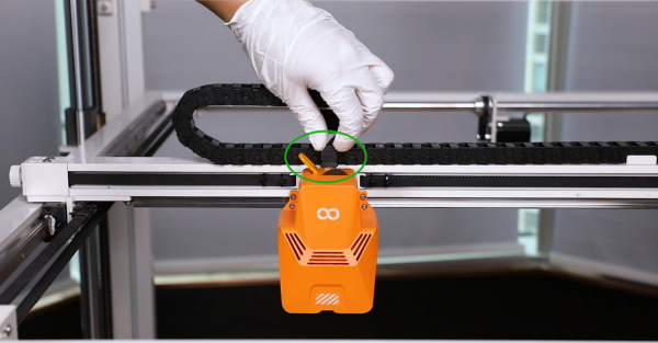
- Unplug the ribbon cables above the printing head.
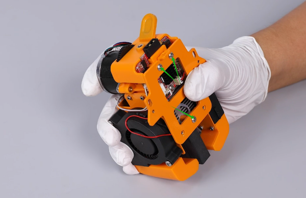
- Loosen the 2 screws securing the rear of the printing head using a 2.0 mm Allen wrench.
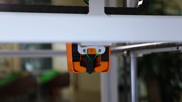
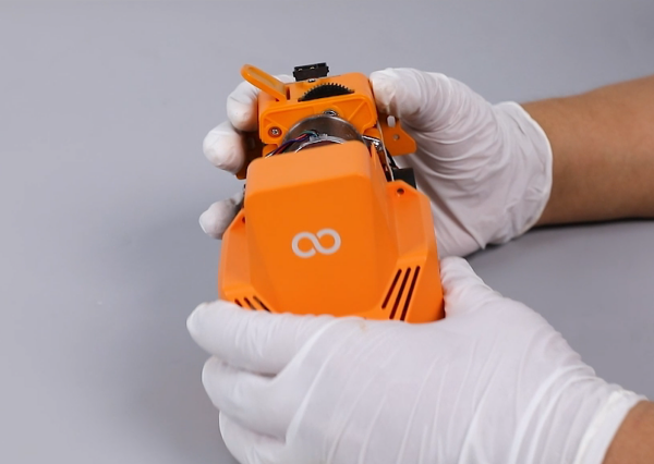
- Loosen the 2 screws securing the front of the printing head using a 2.0 mm Allen wrench and remove the printing head.
Note: Hold the printing head while loosening the last screw to prevent it from falling.
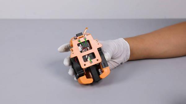
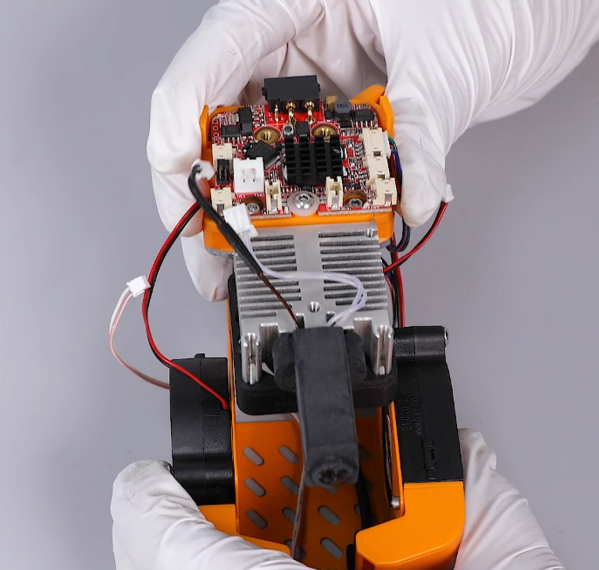
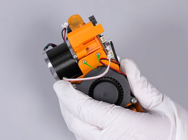
- Loosen the 2 screws securing the front cover of the printing head using a 2.0 mm Allen wrench and remove the front cover.

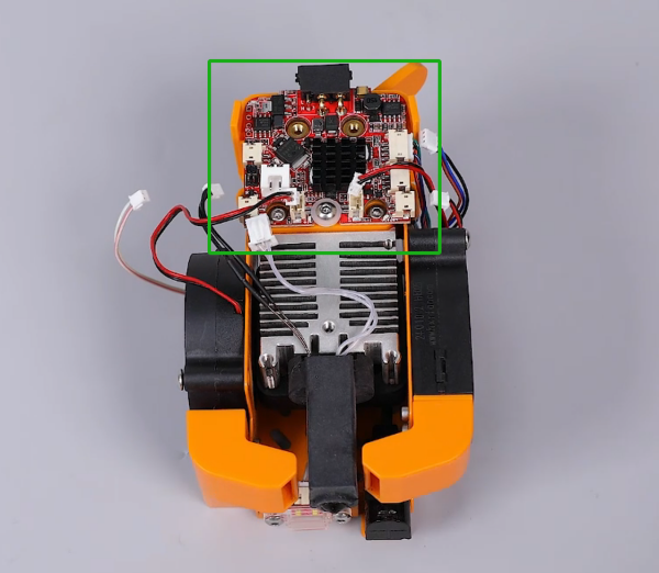
- Loosen the 3 screws securing the back plate of the printing head using a 2.0 mm Allen wrench and remove the back plate and the pressing plate of the adapter board.
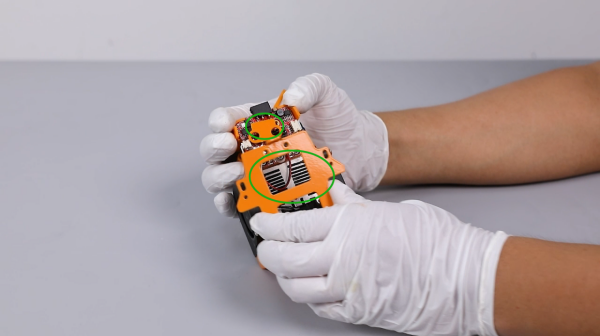
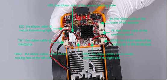
- Unplug the ribbon cables from the ports on the adapter board of the printing head EXCEPT for the E0 (extruder motor) port.
- Loosen the 4 screws securing the left and right side of the model cooling fan bracket using a 1.5 mm Allen wrench.
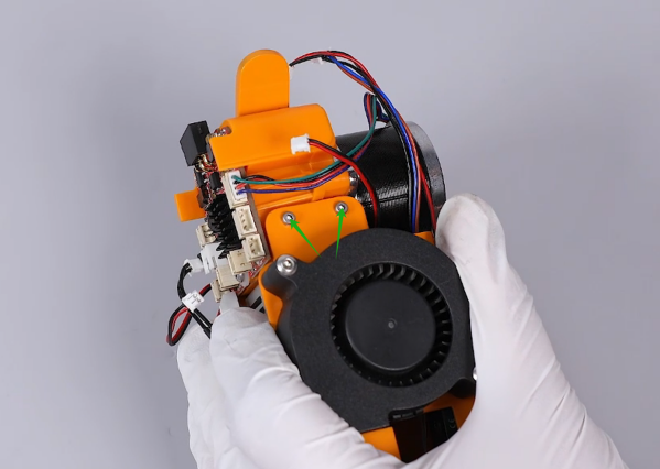

- Remove the model cooling fan assembly.
- Loosen the 4 screws securing the throat cooling fan using a 2.0 mm Allen wrench and remove the old throat cooling fan.
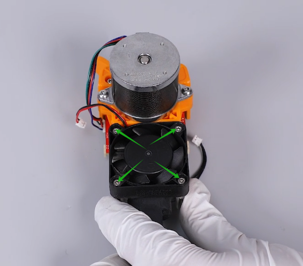
- Prepare the new throat cooling fan. Put it in the installation position by aligning it with the screw holes, and tighten the 4 securing screws using a 2.0 mm Allen wrench.

- Prepare the model cooling fan assembly. Put it in the installation position by aligning it with the screw holes, and tighten the 4 securing screws using a 1.5 mm Allen wrench.

- Insert the ribbon cables to the adapter board of the printing head according to their function and port shape.
- Prepare the back plate of the printing head and the pressing plate of the adapter board. Attach pressing plate onto the screw holes on the back plate of the printing head.
Note: The pressing plate of the adapter board has its fixed installation direction.
- Put the back plate assembly in the installation position by aligning it with the screw holes. Tighten the 3 securing screws using a 2.0 mm Allen wrench.
- Put the front cover in the installation position by aligning it with the screw holes, and tighten the 2 securing screws using a 2.0 mm Allen wrench.
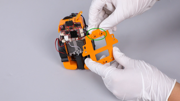
- Put the entire printing head in the installation position by aligning it with the screw holes, and tighten the 2 securing screws using a 2.0 mm Allen wrench.

- Note: Align the level of the screw holes above the back plate with the top of the mounting bracket of the printing head .
- Tighten the 2 screws securing the rear of the print head using a 2.0 mm Allen wrench.

- Plug the ribbon cables above the printing head.
- Power on the printer.
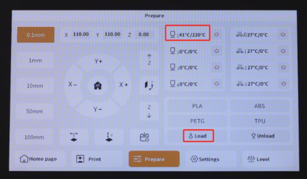
- Touch "Prepare" and set the nozzle temperature to 220 °C. After the temperature reaches to the set temperature, touch "Load" on the touchscreen.
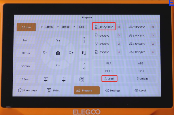
- The printer can be used normally after the filament is extruded normally and the printer is re-leveled.