¶ Tools and Materials
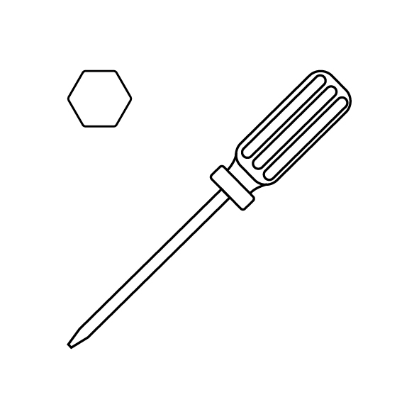
- A 1.5 mm Allen wrench
- A 2.0 mm Allen wrench
- A new extruder gearbox
¶ Tutorial Video
¶ Operation Steps
- Power off the printer and unplug the power cord.
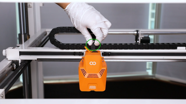
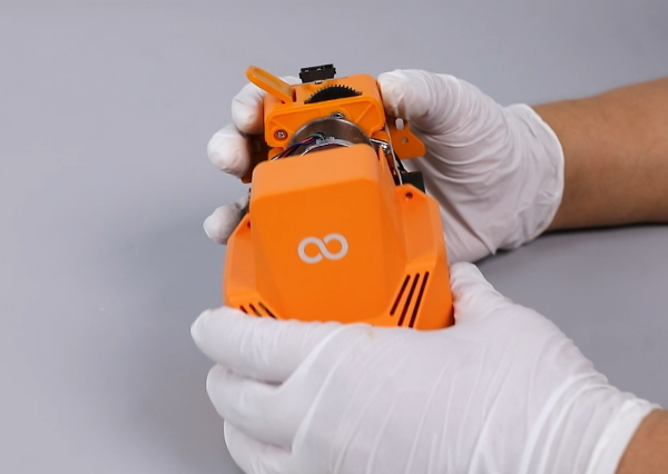
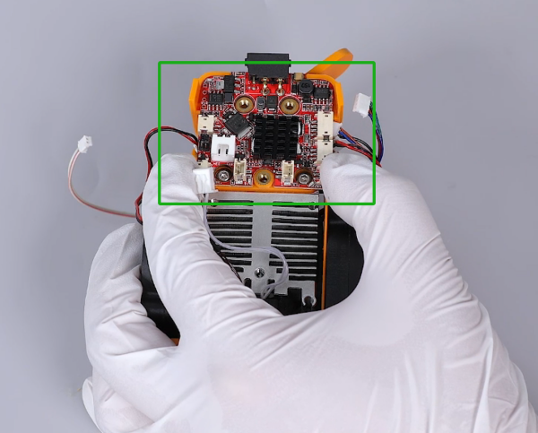
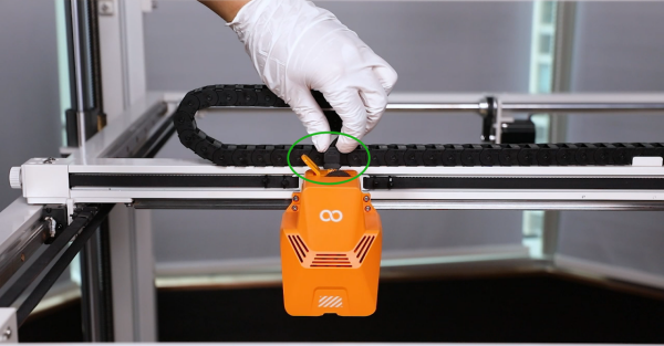
- Unplug the ribbon cables above the printing head.
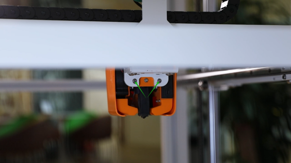
- Loosen the 2 screws securing the rear of the print ing head using a 2.0 mm Allen wrench.
- Loosen the 2 screws securing the front of the printing head using a 2.0 mm Allen wrench and remove the entire printing head.
Note: Holding the printing head while loosening the last screw to prevent it from falling.

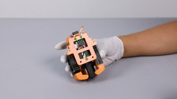
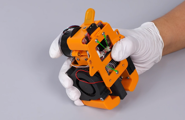
- Loosen the 2 screws securing the front cover of the printing head using a 2.0 mm Allen wrench and remove the front cover.

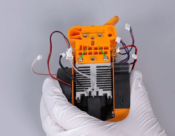
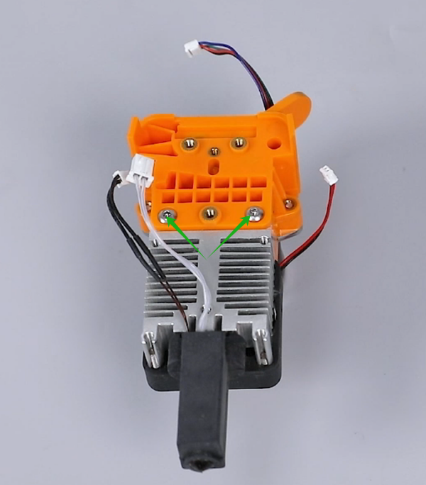
- Loosen the 3 screws securing the back plate of the printing head using a 2.0 mm Allen wrench and remove the back plate of the printing head and pressing plate of the adapter board.
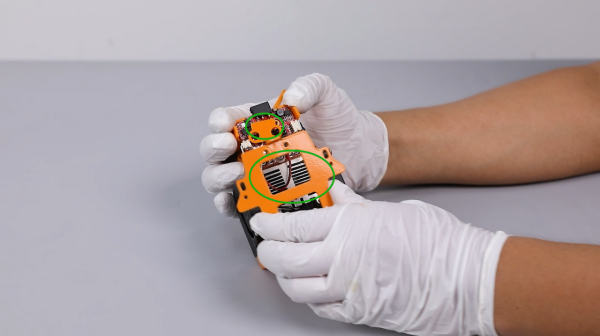
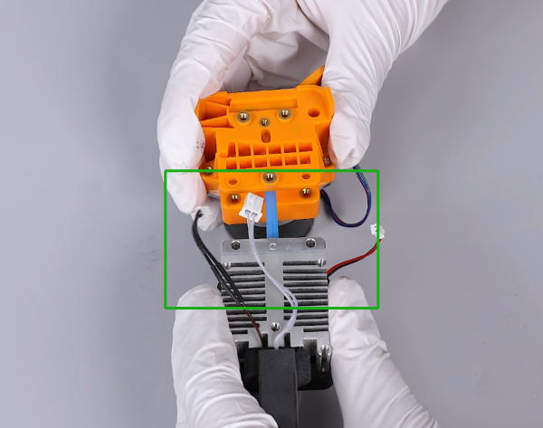
- Unplug all ribbon cables from the ports on the adapter board of the printing head.
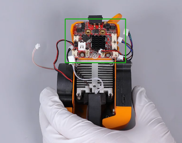
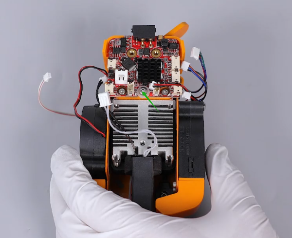
- Loosen the screw securing the adapter board of the printing head using a 2.0 mm Allen wrench and remove the adapter board.

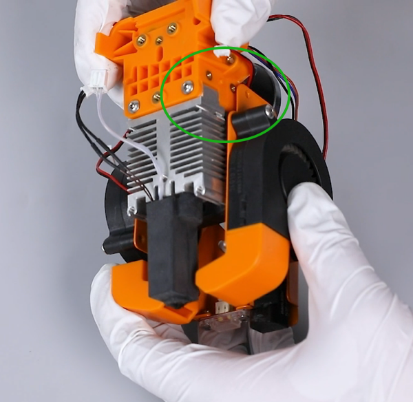
- Loosen the 2 screws securing the printing head assembly using a 2.5 mm Allen wrench.
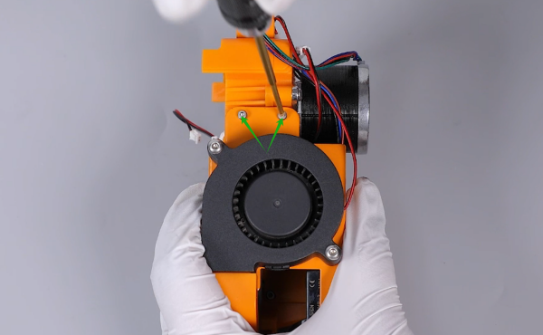
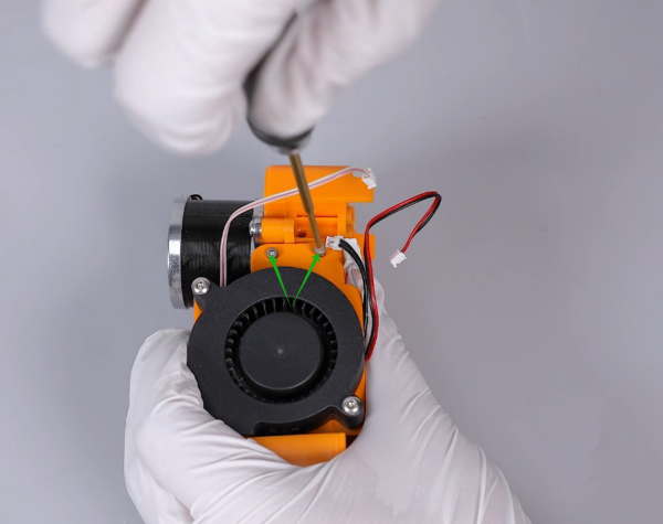
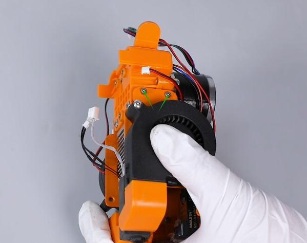
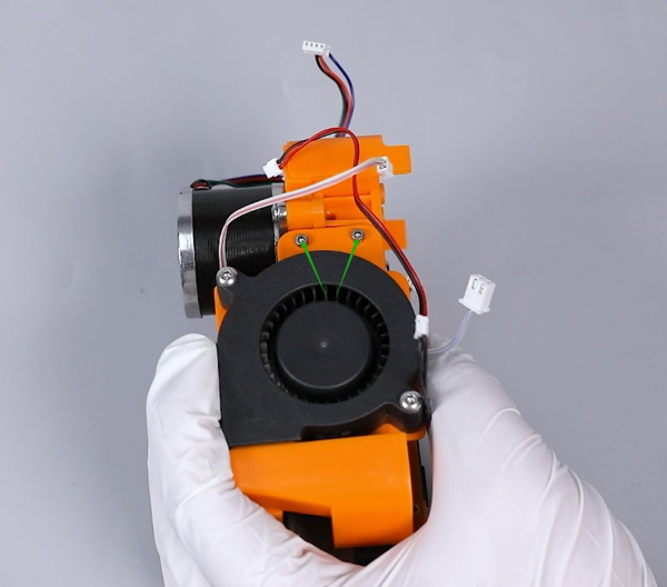
- Loosen the 4 screws securing the model cooling fan bracket on both sides using a 1.5 mm Allen wrench and remove the model cooling fan assembly.
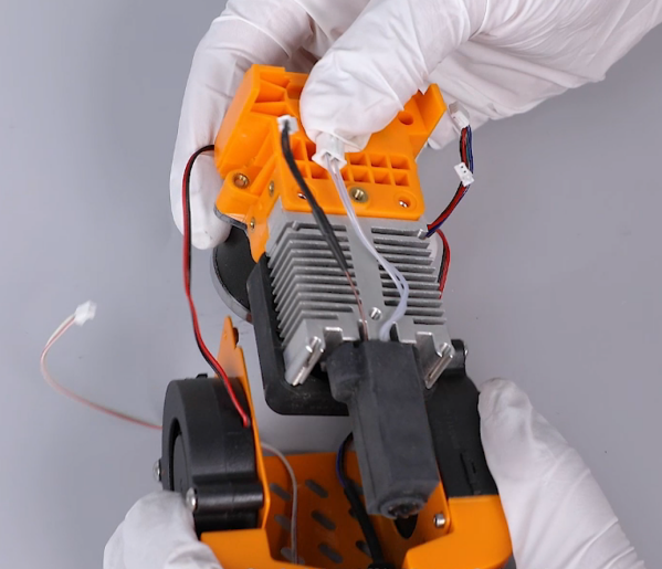
- Remove the printing head assembly and the PTFE tube.
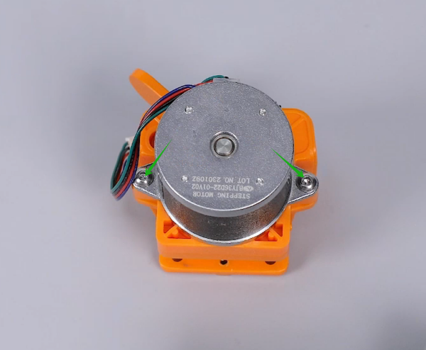
- Loosen the 2 screws securing the motor of the extruder using a 2.5 mm Allen wrench and remove the old extruder gearbox.
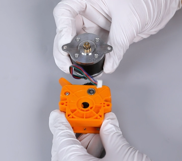
- Prepare the new extruder gearbox. Put place the new extruder gearbox in the installation position by aligning the motor with the screw holes. Tighten the 2 securing screws using a 2.5 mm Allen wrench.

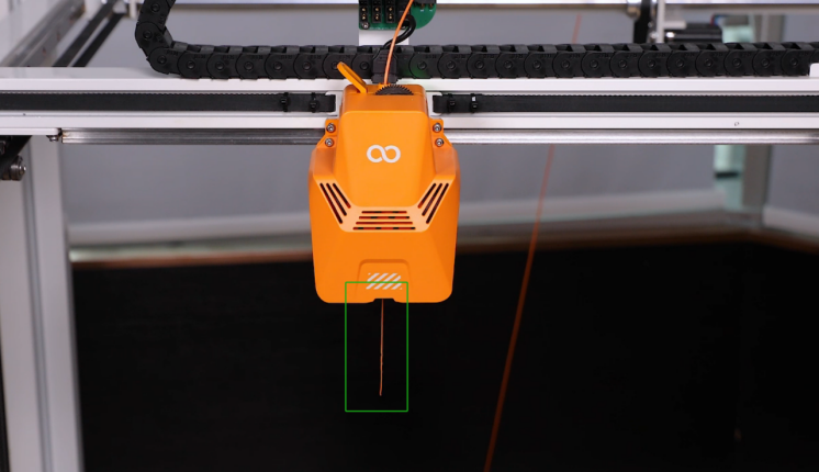
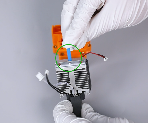
- Prepare the new printing head assembly and the new PTFE tube. Insert the PTFE tube into the throat tube of the heat dissipation device, and push it to the bottom.
- Put the printing head assembly in the installation position by aligning it with the filament passing holes of the gearbox. Tighten the 2 securing screws using a 2.5 mm Allen wrench.
- Prepare the model cooling fan assembly. Put it in the installation position by aligning it with the screw holes. Tighten the 4 securing screws using a 1.5 mm Allen wrench.
- Prepare the adapter board of the printing head. Put it in the installation position by aligning it with the screw holes.
- Put the gasket in the installation position by aligning it with the screw holes. Tighten the screw securing the adapter board of the printing head using a 2.0 mm Allen wrench.
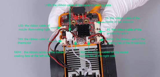
- Insert the ribbon cables into the adapter board of the printing head according to the markings.
- Prepare the the back plate of the printing head and the pressing plate of the adapter board. Attach the pressing plate of the adapter board onto the screw holes of the pressing plate of the adapter board.
Note: The pressing plate of the adapter board has its fixed installation direction.
- Put the back plate assembly of the printing head in the installation position by aligning it with the screw holes. Tighten the 3 securing screws using a 2.0 mm Allen wrench.
- Put the front cover in the installation position by aligning it with the screw holes and tighten the 2 securing screws using a 2.0 mm Allen wrench.
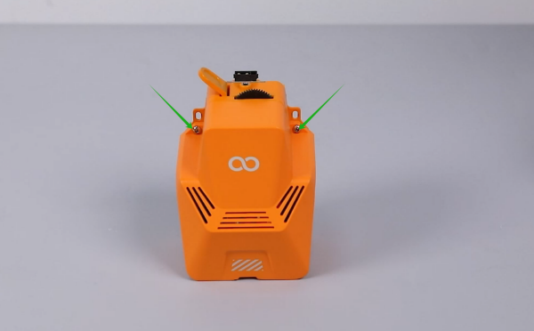
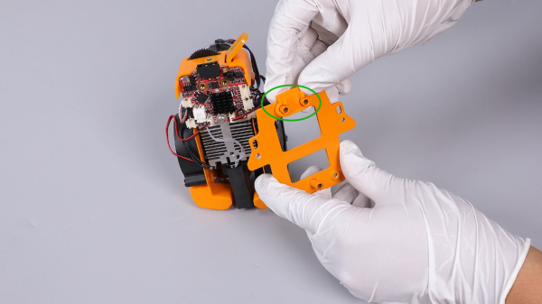
- Put the entire printing head in the installation position by aligning it with the screw holes, and tighten the 2 securing screws using a 2.0 mm Allen wrench.
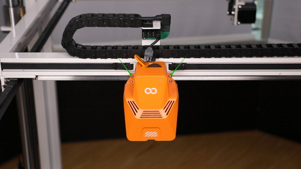
- Note: Align the level of the screw holes above the two sides of the back plate with the top of the mounting bracket of the printing head.
- Tighten the 2 screws securing the rear of the printing head using a 2.0 mm Allen wrench.
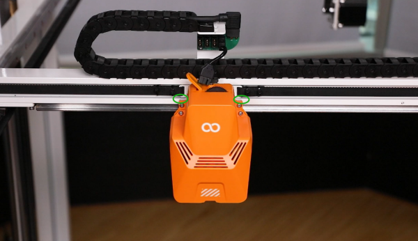
- Insert the ribbon cables of the printing head to their original positions.
- Power on the printer.
- Touch "Prepare" and set the nozzle temperature to 220 °C. After the temperature reaches to the set temperature, touch "Load" on the touchscreen.
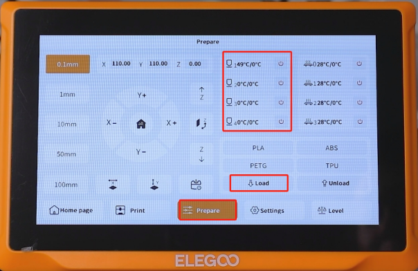
- The printer can be used as usual after the filament is extruded normally and the printer is re-leveled.