¶ Tools and Materials
-
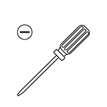
A flat head screwdriver
-
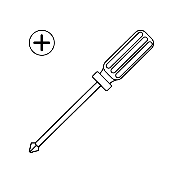
A Phillips screwdriver
-
A new motherboard
¶ Instruction
¶ Preparation
Turn the power switch OFF (symbol "〇") and unplug the power supply cable.
¶ Remove the old motherboard
-
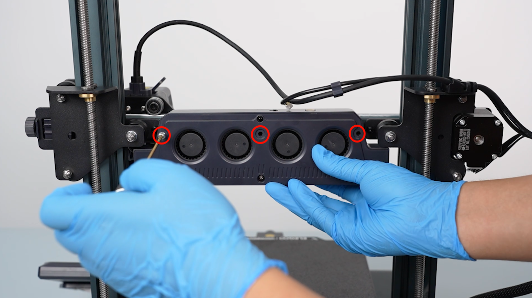
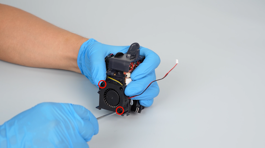
Loosen the five screws securing the bottom cover with a Phillips screwdriver.
-
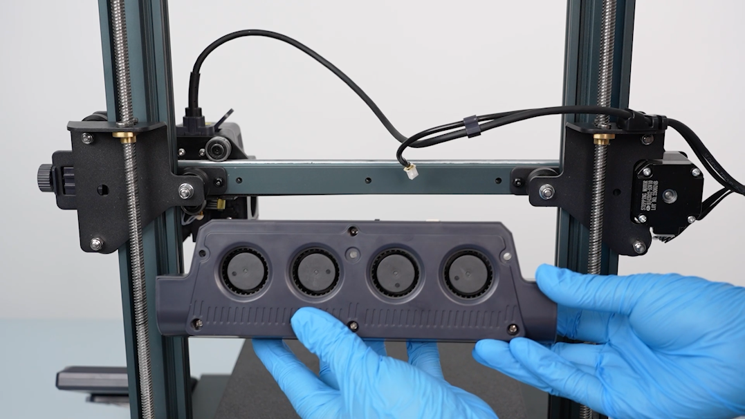
Open the bottom cover carefully. Disconnect the cable of the motherboard cooling fan and remove the bottom cover.
-
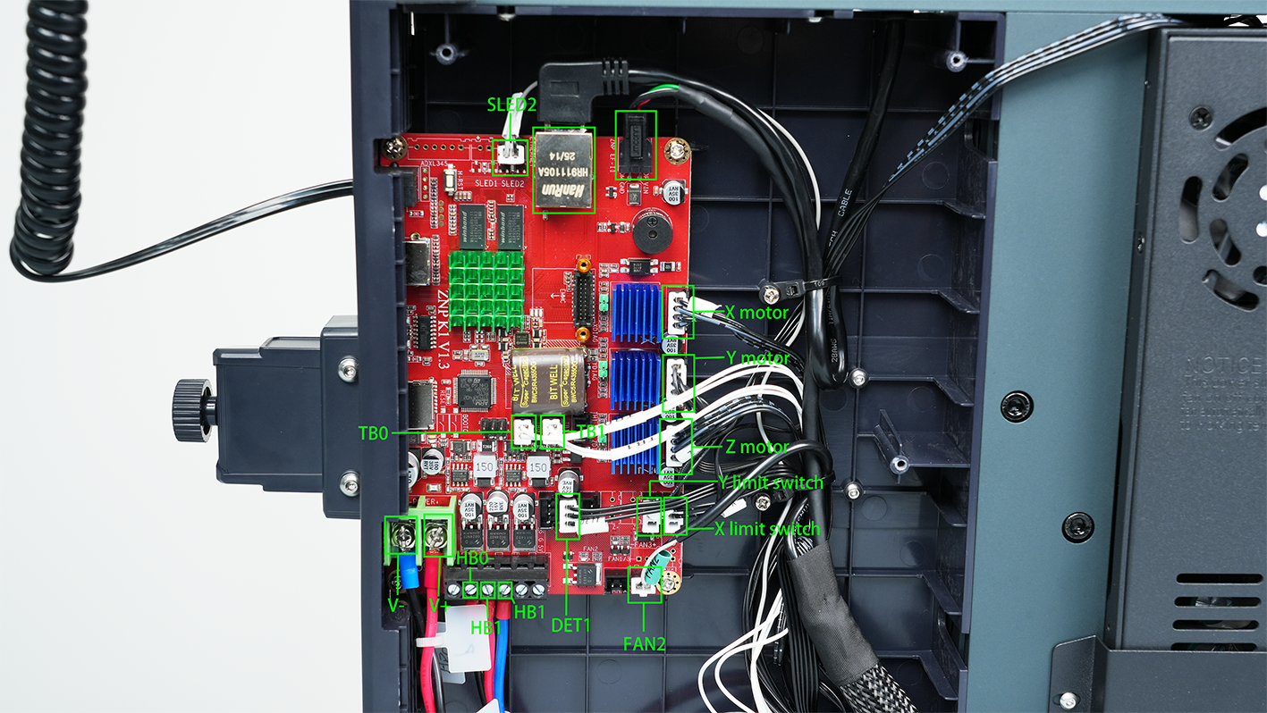
Use labelled cable ties to mark the unlabelled cable and make sure the cables correspond to the port names on the motherboard.
-
Remove the hot-melt adhesive securing the cable in the top-left corner with a pair of pliers.
-
Unplug the cables connected to the motherboard.
-
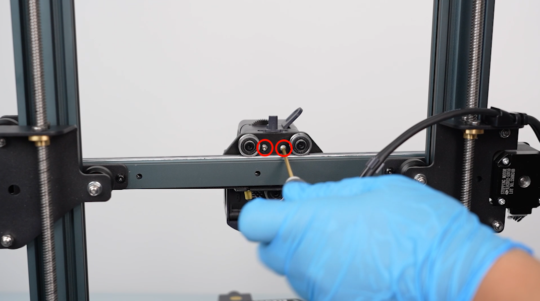
Use a flathead screwdriver to loosen the screws securing the heated bed wire by turning them anti-clockwise. Unplug the heated bed wire.
Note: If the heated bed wire is difficult to unplug, loosen the screws again. Do not force the cable out.
-
Turn the screws securing the motherboard wires anticlockwise with a Phillips screwdriver and loosen them. Remove the wires.
-
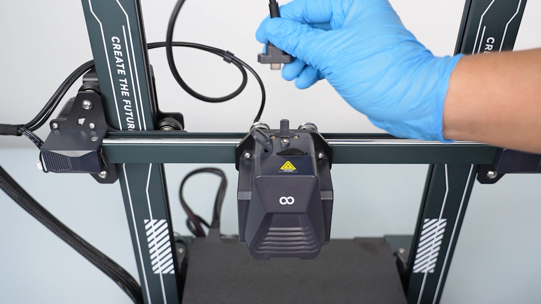
Disconnect the touch screen wire.
-
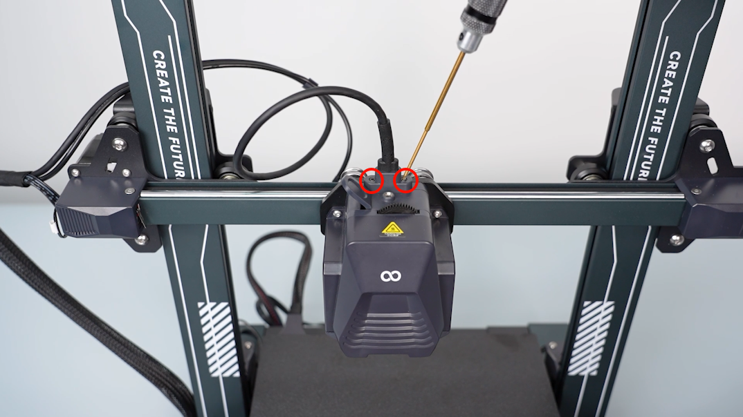
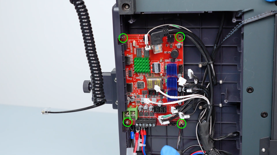
Loosen the four screws securing the motherboard with a Phillips screwdriver and remove the old motherboard.
¶ Install the new motherboard
-
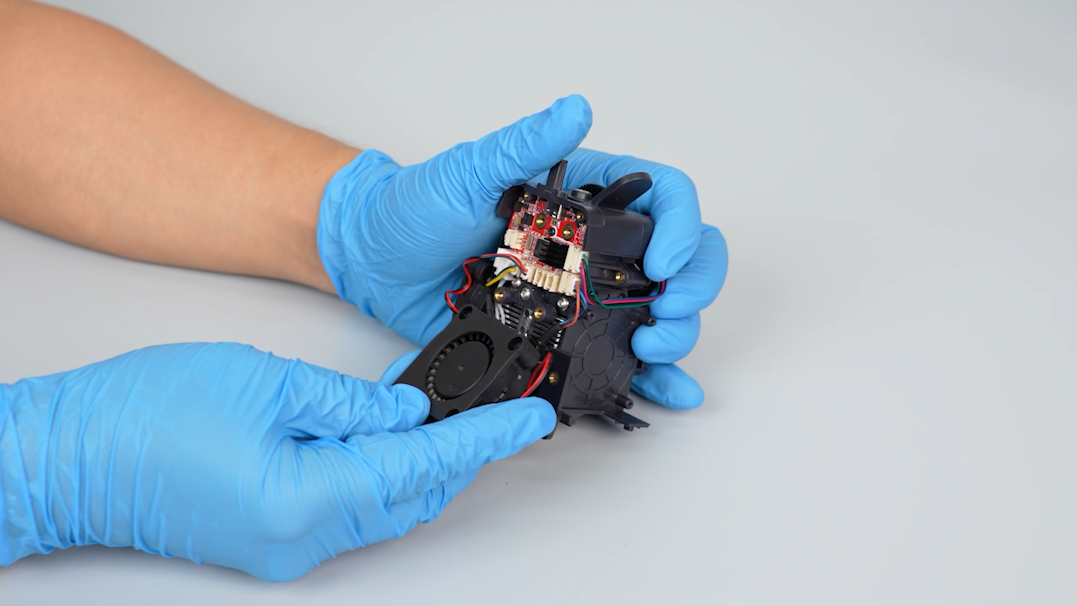
Align the new motherboard with the screw holes and the slots on the side of the base. Press it and put it in the installation position.
-
Tighten the four screws securing the motherboard with a Phillips screwdriver.
-
Insert the plugs accoridng to the labels into the ports on the motherboard.
-
Loosen the screws of the new motherboard and power supply ports. Plug in the power supply cable according to the cable ties.
-
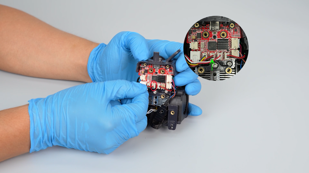
Loosen the screws securing the motherboard wires with a Phillips screwdriver. Insert the motherboard wires and tighten the screws.
Note: The red wire connects with the positive port (marked +) and the black wire connects with the negative port (marked --). Do not insert the wires incorrectly, as this may damage the motherboard.
-
Put the touch screen on the bracket and plug in the connection wire.
-
Get the bottom cover and plug in the motherboard cooling fan cable.
-
Tighten the five screws securing the bottom cover with a Phillips screwdriver.
¶ Verification
-
Plug in the power supply cable and turn the power switch ON (symbol "|").
-
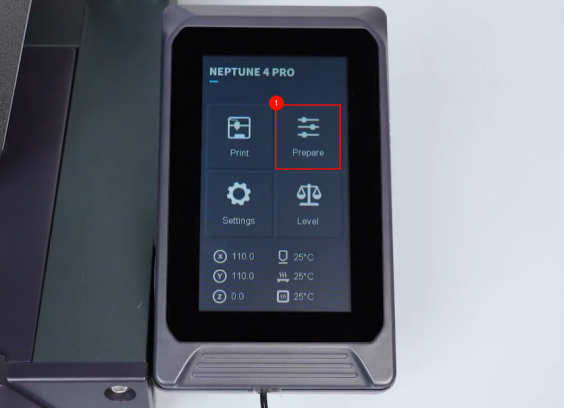
On the touch screen, preheat the printer.
-
After the temperature reaches the preset value, reset the Z-offset value and re-level the printer. And the printer is ready for use.