¶ Tools and Materials
-
A 2.0 mm Allen key
-
A 2.5 mm Allen key
-
A Phillips screwdriver
-
A new model light
¶ Tutorial Video
https://www.youtube.com/watch?v=ilmIy308yrY
¶ Instruction
¶ Preparation
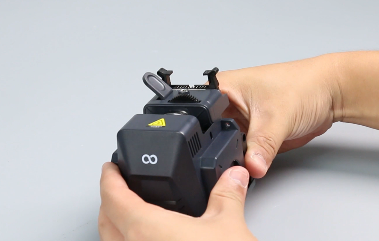
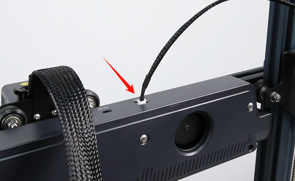
Turn the power switch OFF (symbol "〇"). Unplug the power supply cable.
¶ Remove the old model light
-
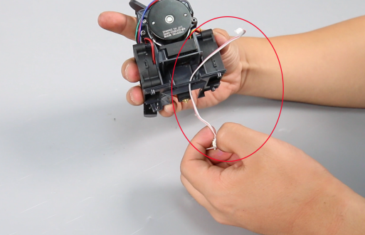
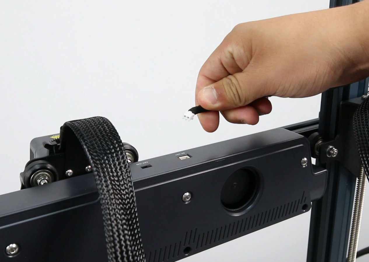
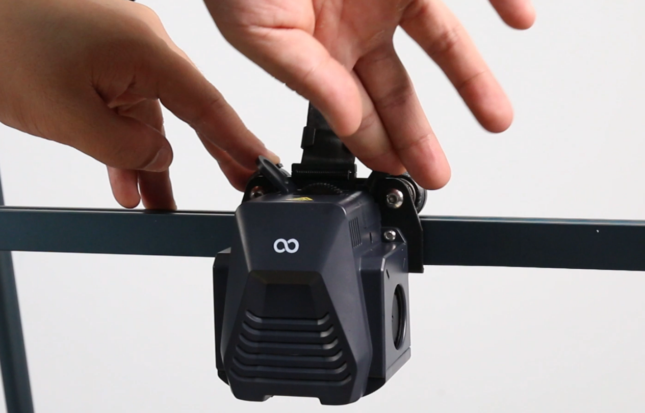
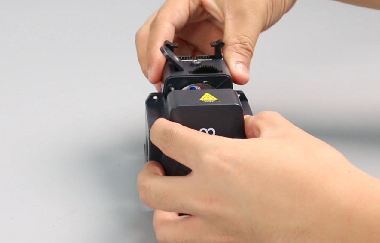
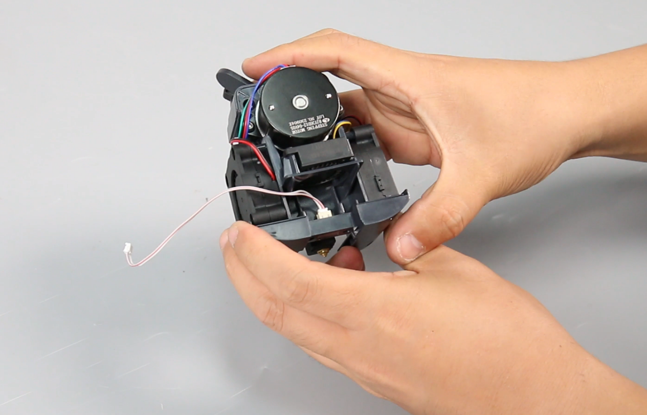
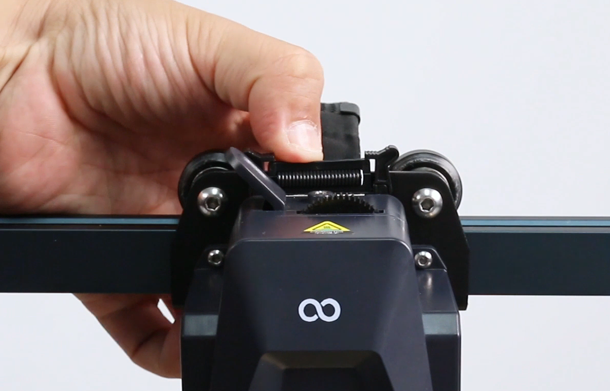
Remove the plug of the rear fan assembly cable.
-
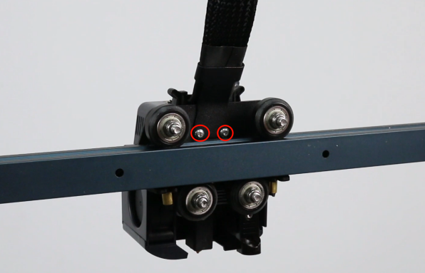
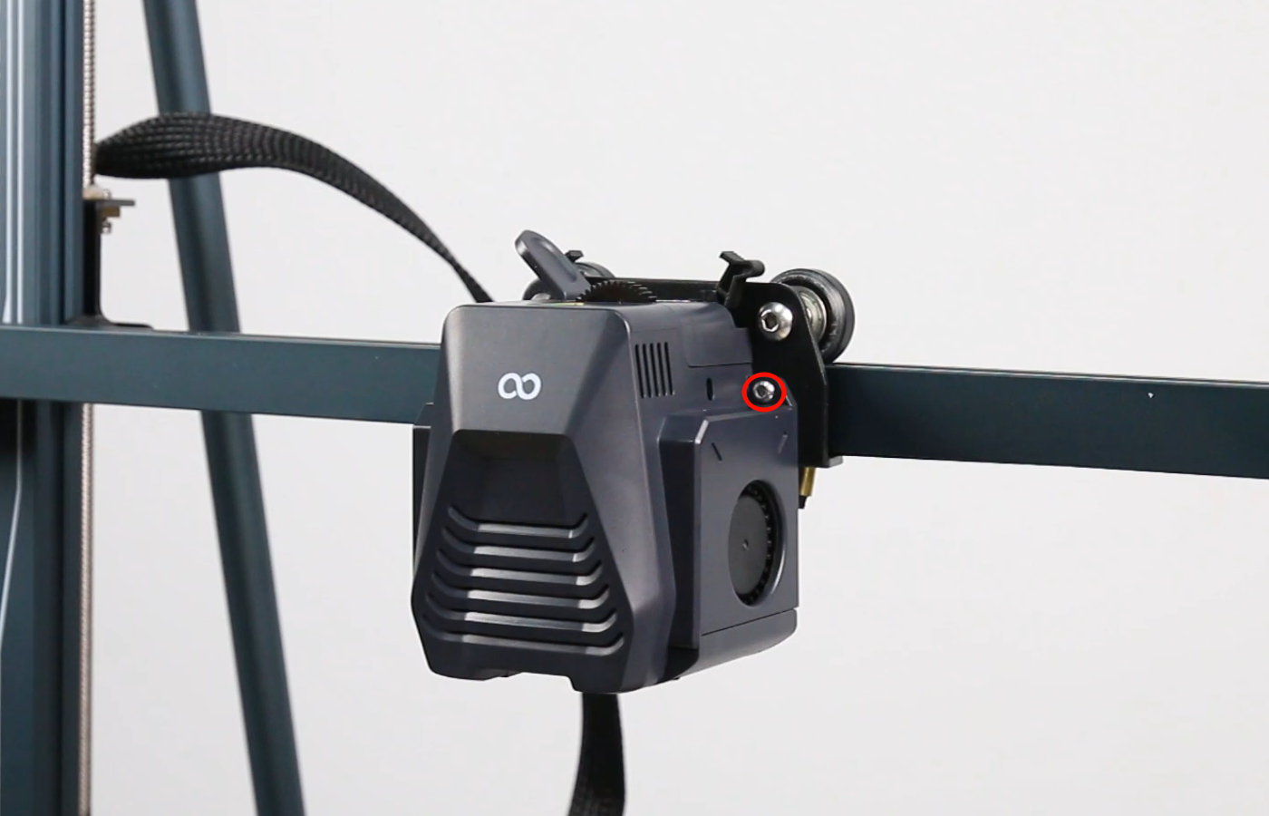
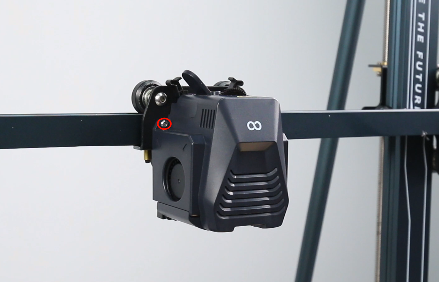
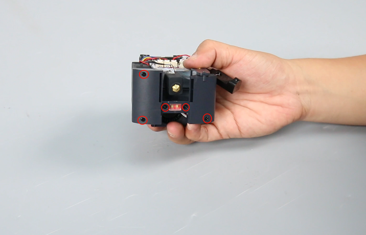
Loosen the four screws secruing the rear fan assembly with a 2.5 mm Allen key and remove the rear fan assembly.
Note: Hold the rear fan assembly when releasing the last screw.

-
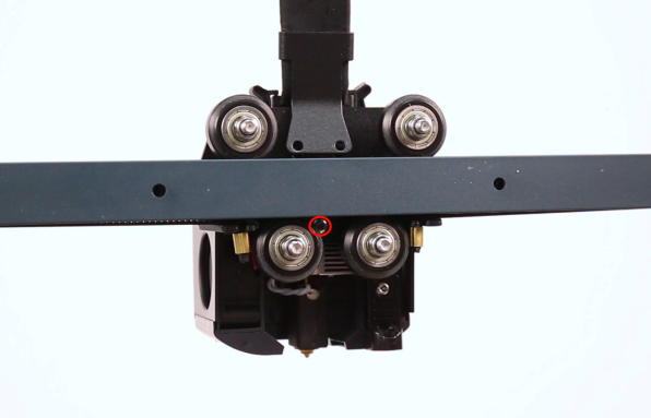
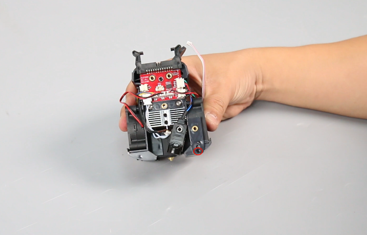
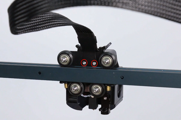
Loosen the two screws securing the cable fastener and the screw of the print head with a 2.0 mm Allen key.
-
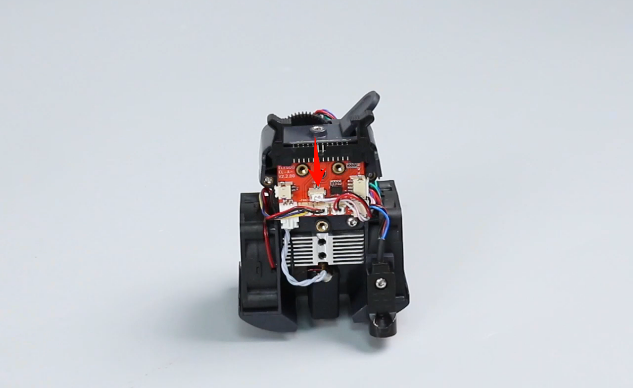
Press the horn terminal and remove the print head cable.
-
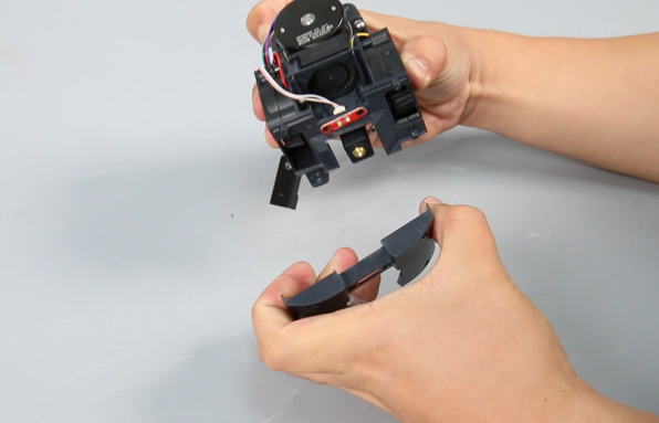
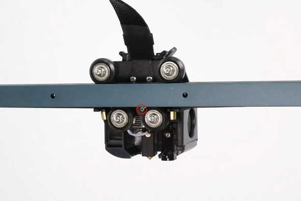
Loosen the two screws securing the print head front cover with a 2.0 mm Allen key and remove the print head.
-
Remove the front cover of the print head assembly.
-
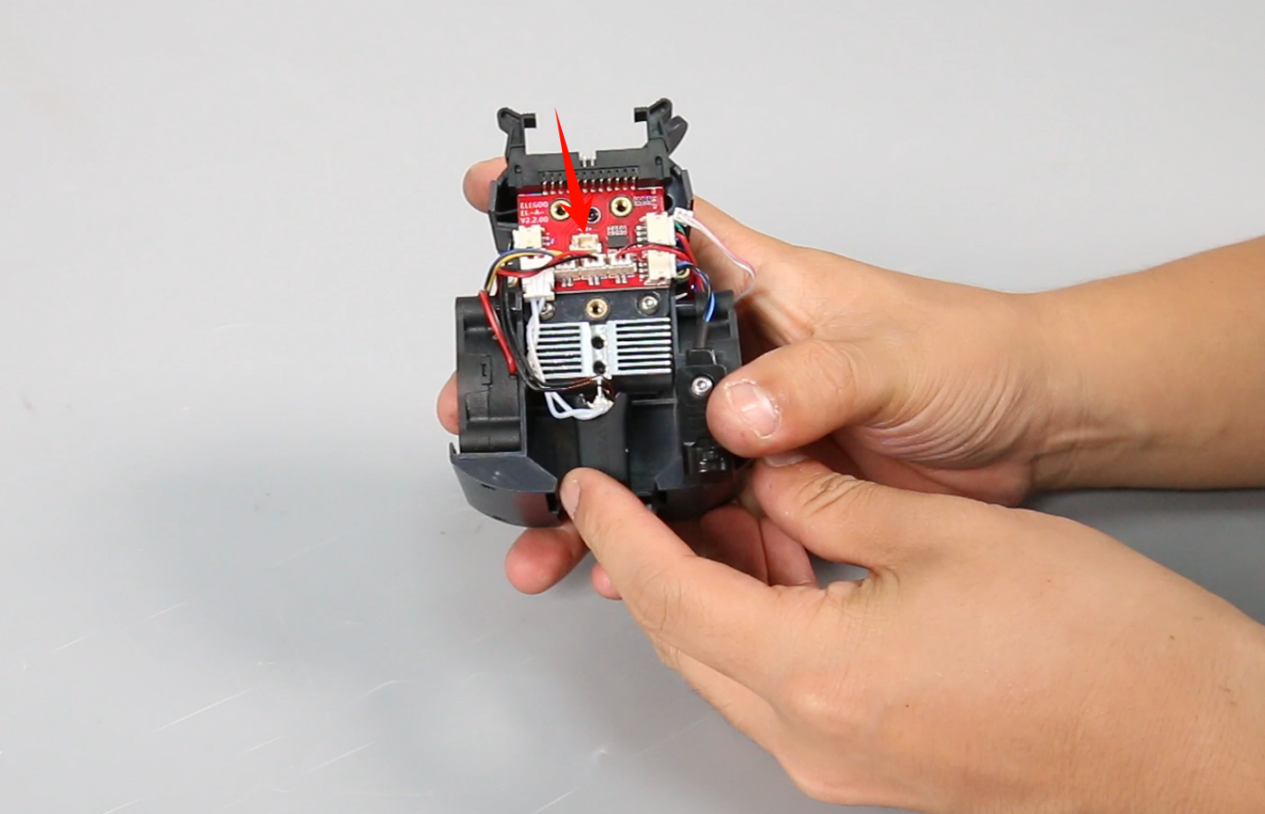
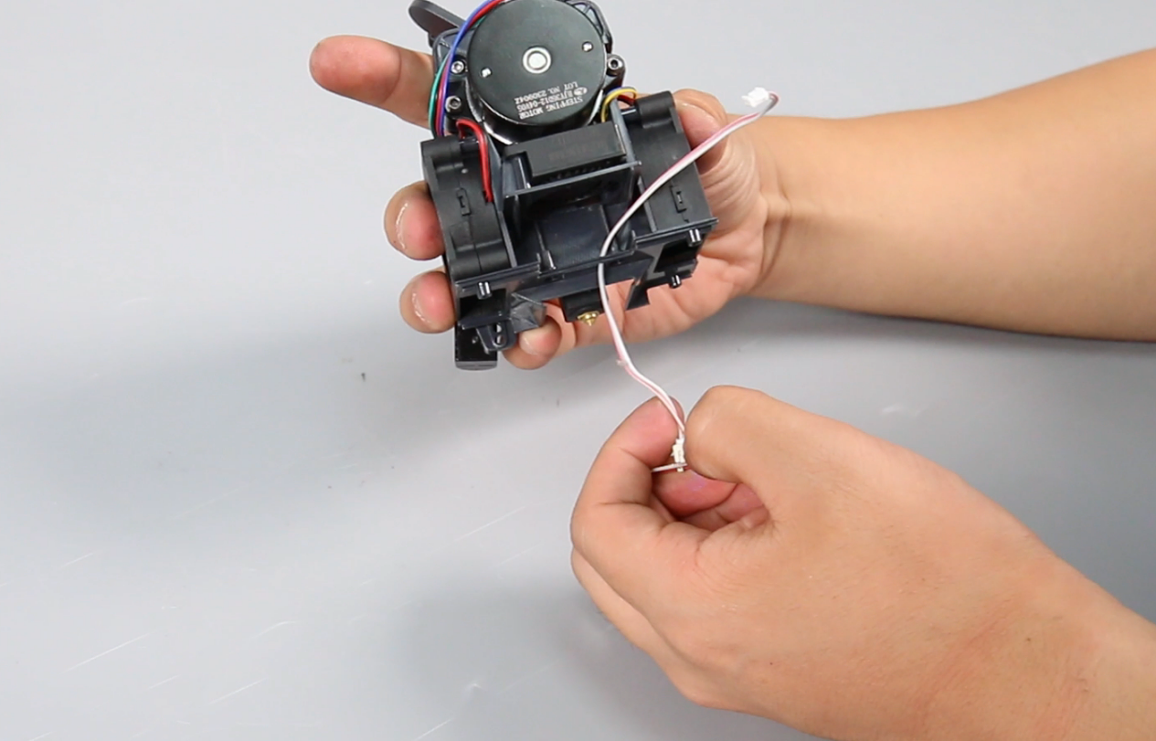
Unplug the model light cable.
-
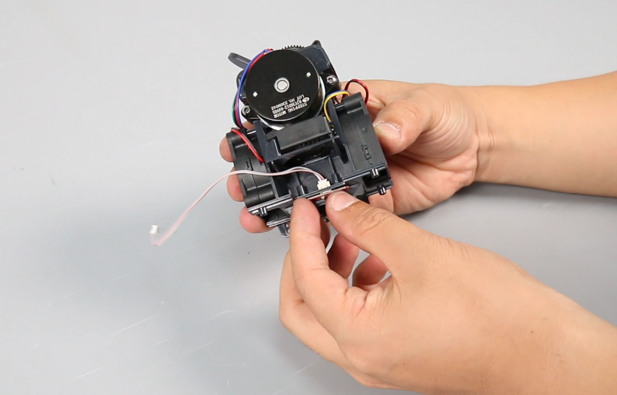
Loosen the screw of the proximity switch with a 2.0 mm Allen key.
-
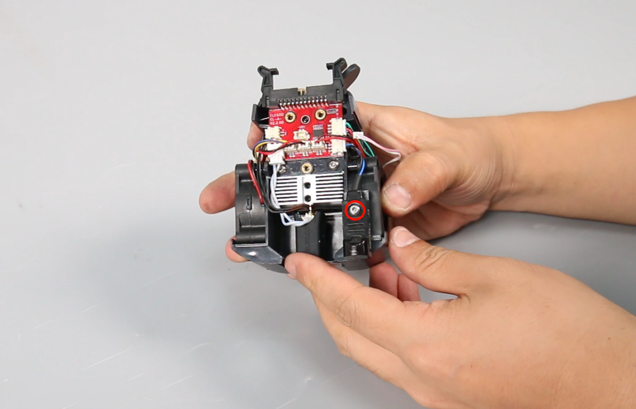
Loosen the screw at the rear of the air guide (under the proximity switch) with a Phillips screwdriver.
-
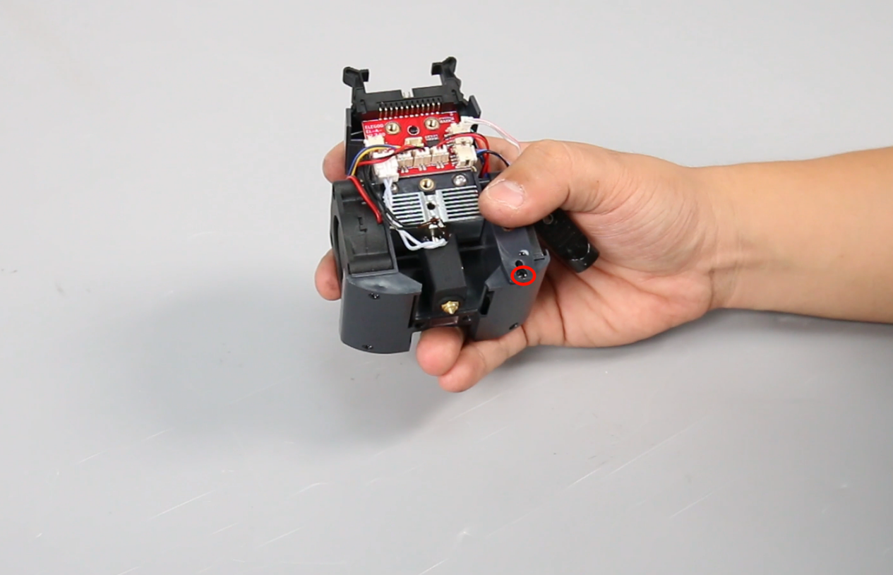
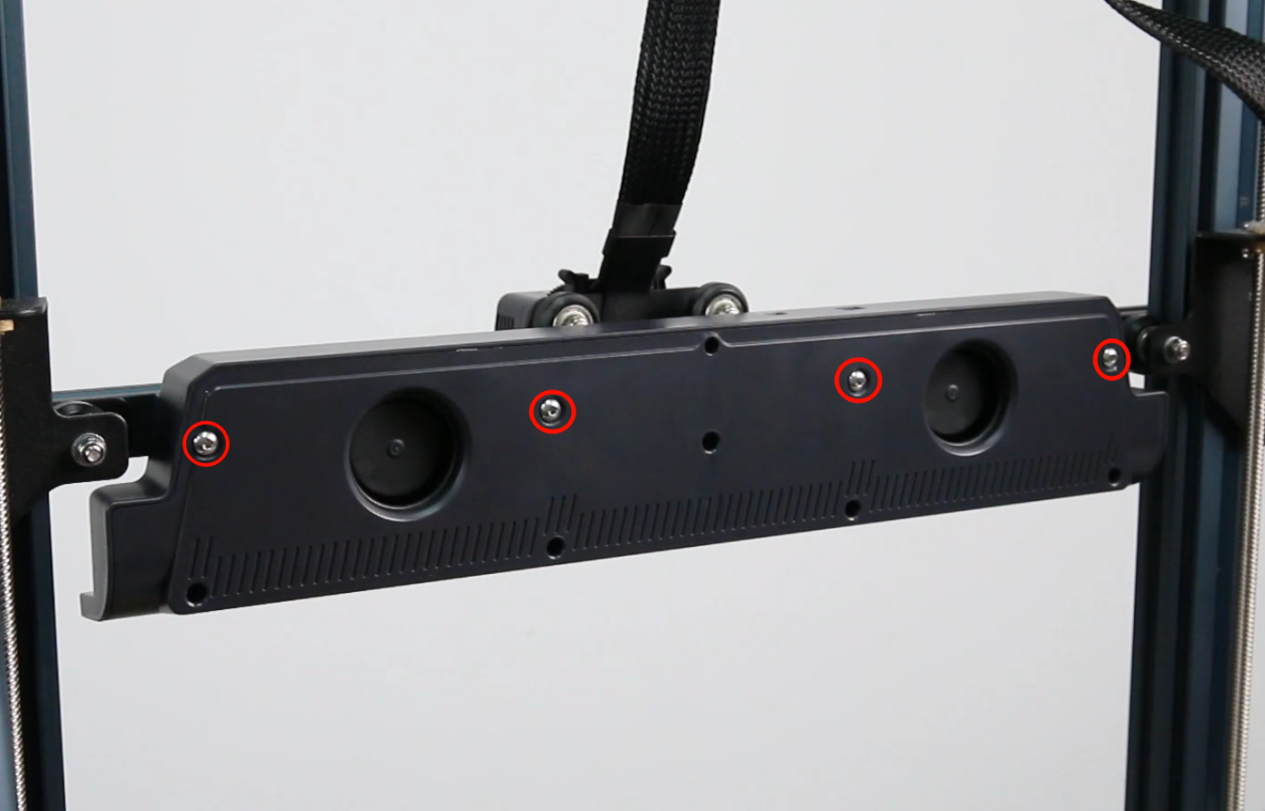
Loosen the five screws at the bottom of the air guide with a Phillips screwdriver and remove the air guide.
Note: There is a buckle design under the left fan, which makes it easier to separate it at the corner position.
-
Remove the model light.
¶ Install the new model light
-
Pass the model light cable through the mounting hole and press the cable.
-
Align the air guide with the screw holes and place it in the mounting position.
-
Tighten the five screws at the bottom of the air guide.
Note: The two screws next to the model light are slightly longer.
-
Tighten a screw at the rear of the air guide (under the proximity switch).
-
Put the proximity switch in the installation position and tighten the screw.

-
Insert the model light cable.
-
Install the front cover of the print head assembly.
Note: The front cover has a groove design and can be installed by sliding it in.
-
Place the print head assembly in the installation position and tighten the two screws of the print head front cover.
-
Press the horn terminal and insert the print head cable.
-
Tighten the two screws of the cable fastener with a 2.0 mm Allen key and the one screw securing the print head assembly.
-
Tighten the four fixing screws securing the rear fan assembly with a 2.5 mm Allen key.
Note: The air outlet must be installed downward.
-
Plug in the rear fan assembly cable.
¶ Verification
-
Plug in the power supply cable. Turn the power switch ON (symbol "|").
-
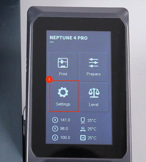
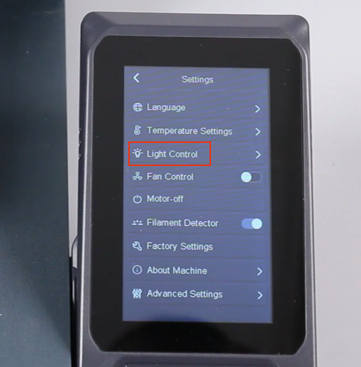
On the touch screen, select Settings - Light Control and turn on the model light.
-
Confirm that the model light turns on normally, the model light is replaced successfully.