¶ Tools and Materials
- A 3.0 mm Allen key
- A 2.5 mm Allen key
- A 2.0 mm Allen key
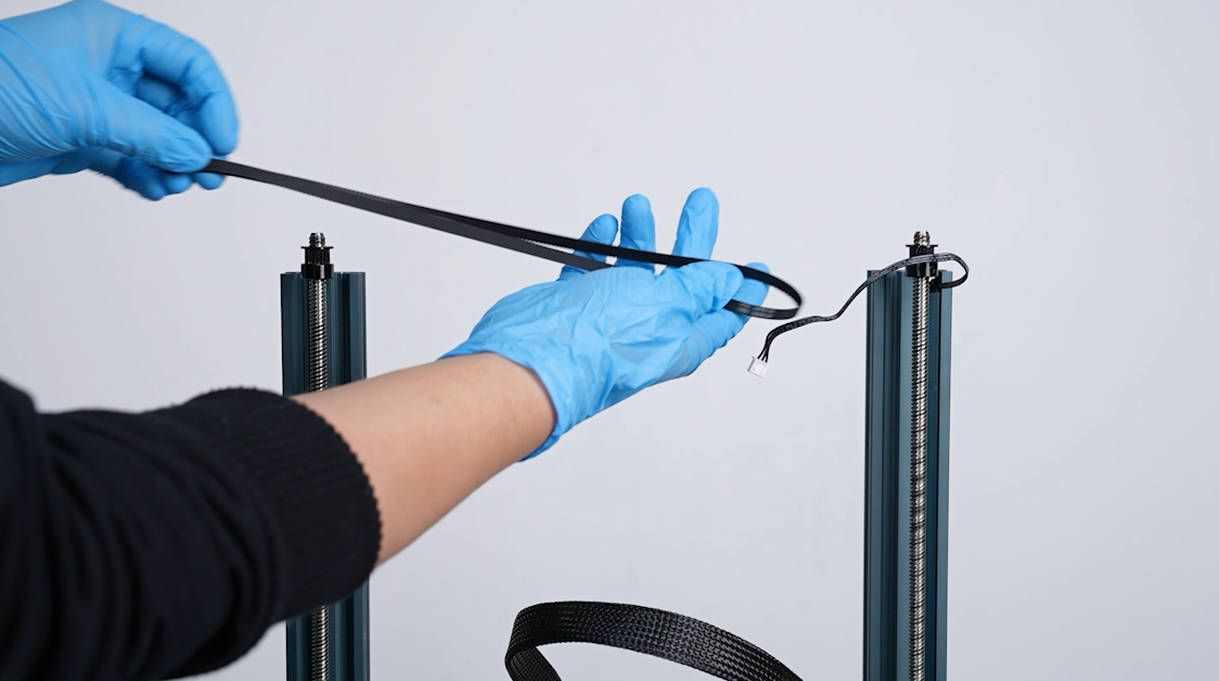
- Cable ties
- Lubricating grease
- Dust-free cloth
- Lubricating grease
- Cuboid x2
- A new lead screw

¶ Tutorial Video
Coming soon.
¶ Instruction
¶ Remove the old lead screw
- Plug in the power cord and power on the printer.
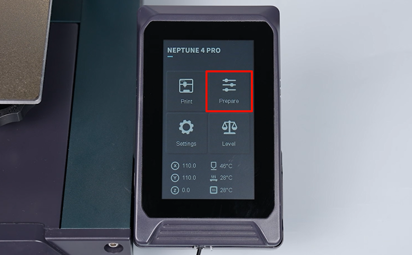
- Select Prepare - All (Homing) on the touchscreen. The printer starts homing process.
- After the homing process, power off the printer and unplug the power cord.
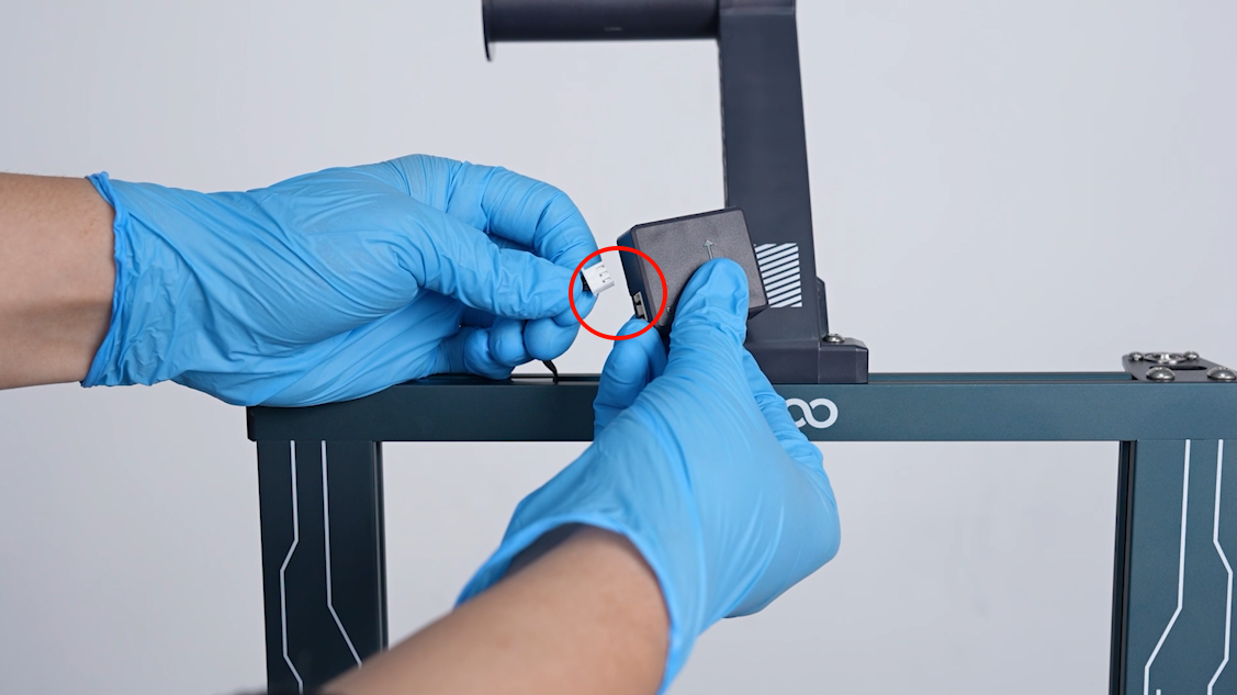
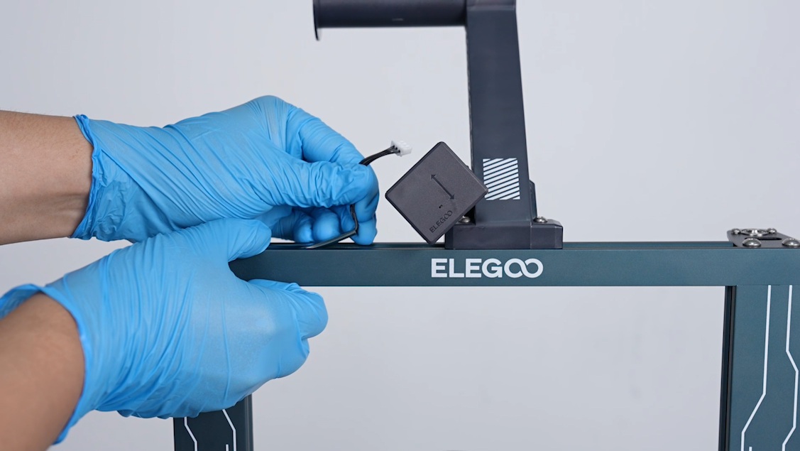
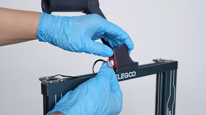
- Unplug the cables of the filament runout detection.
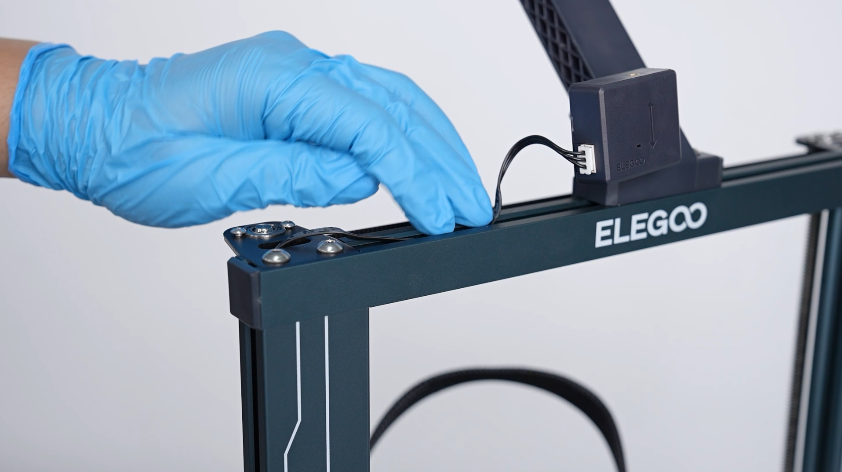
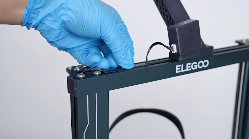
- Organize the cables and remove the cable trunking.
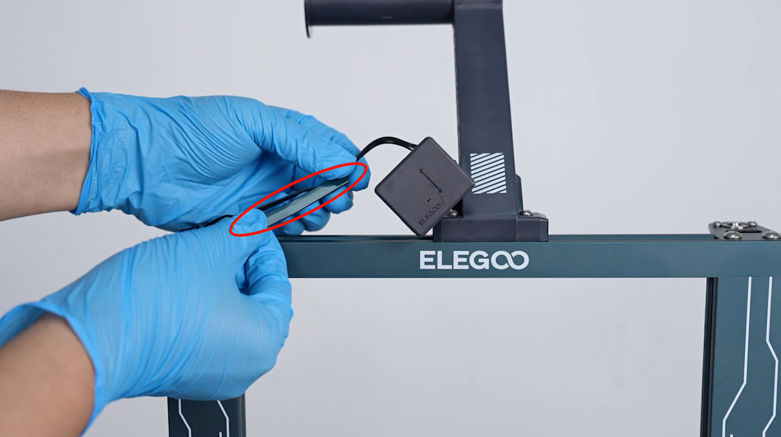
- Pull the cables from the fixing plate at the top left of the printer.
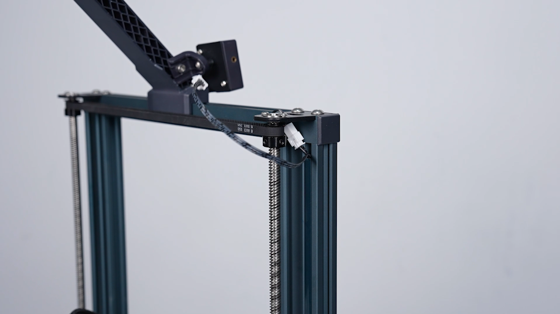
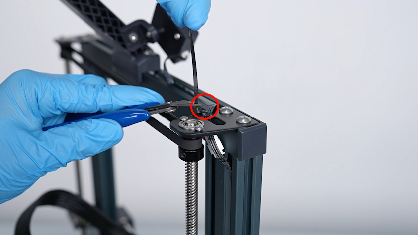
- Cut off the cable ties securing the cables of the top light. Unplug the cable port.
- Loosen the 2 screws securing the fixing plate above the lead screws using a 3.0 mm Allen key. Lift the fixing plate and remove it.
- Remove the fixing plate at the other side.
Note: Hold the top aluminum profile at all times after loosening the screws to prevent it from falling.
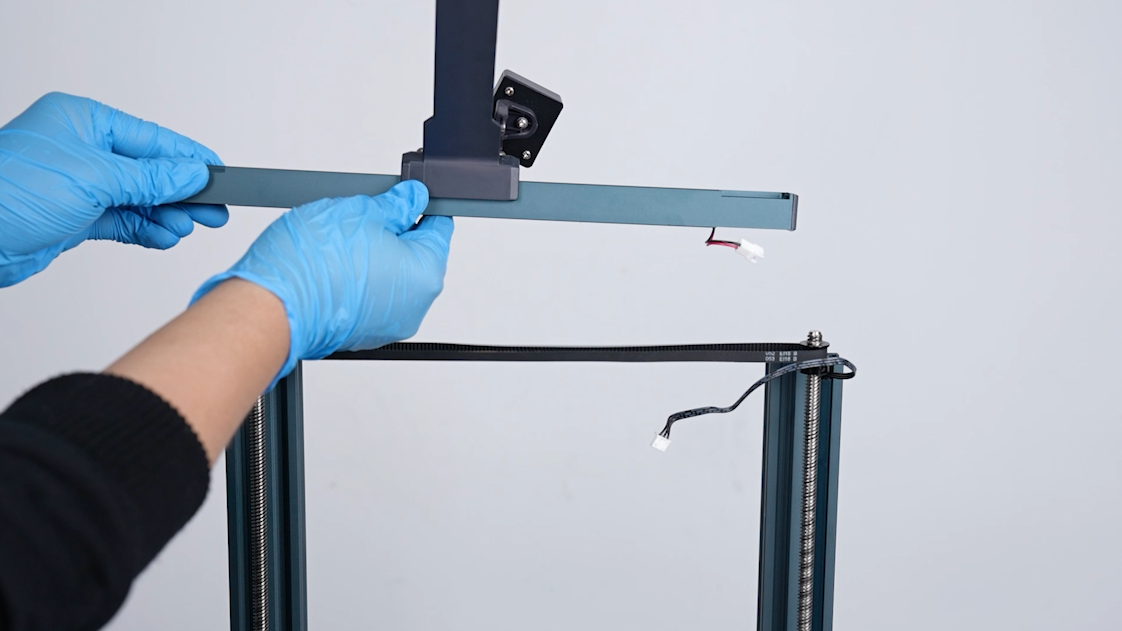
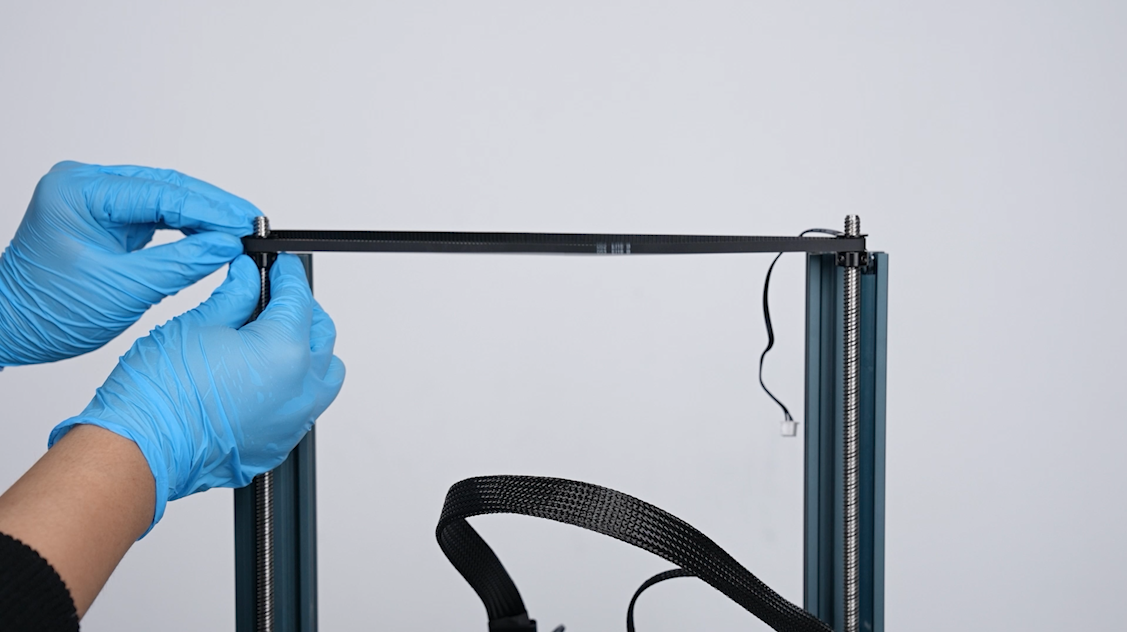
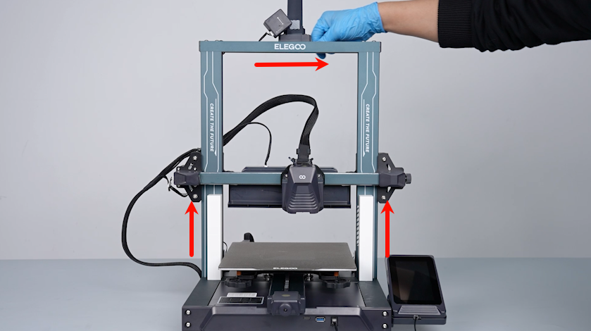
- Lift and remove the aluminum profile. Remove the timing belt.
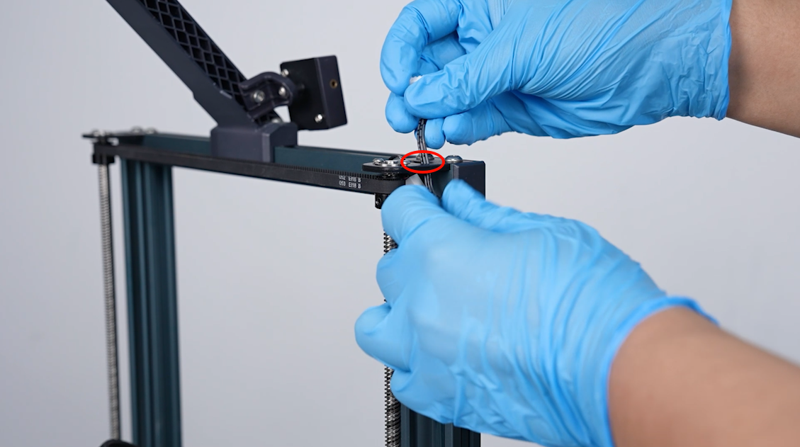
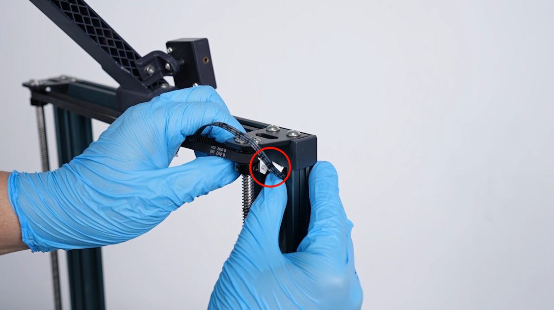
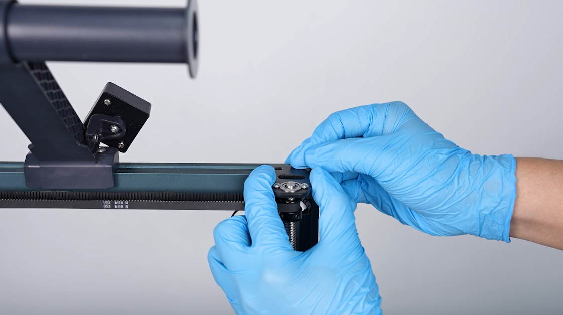
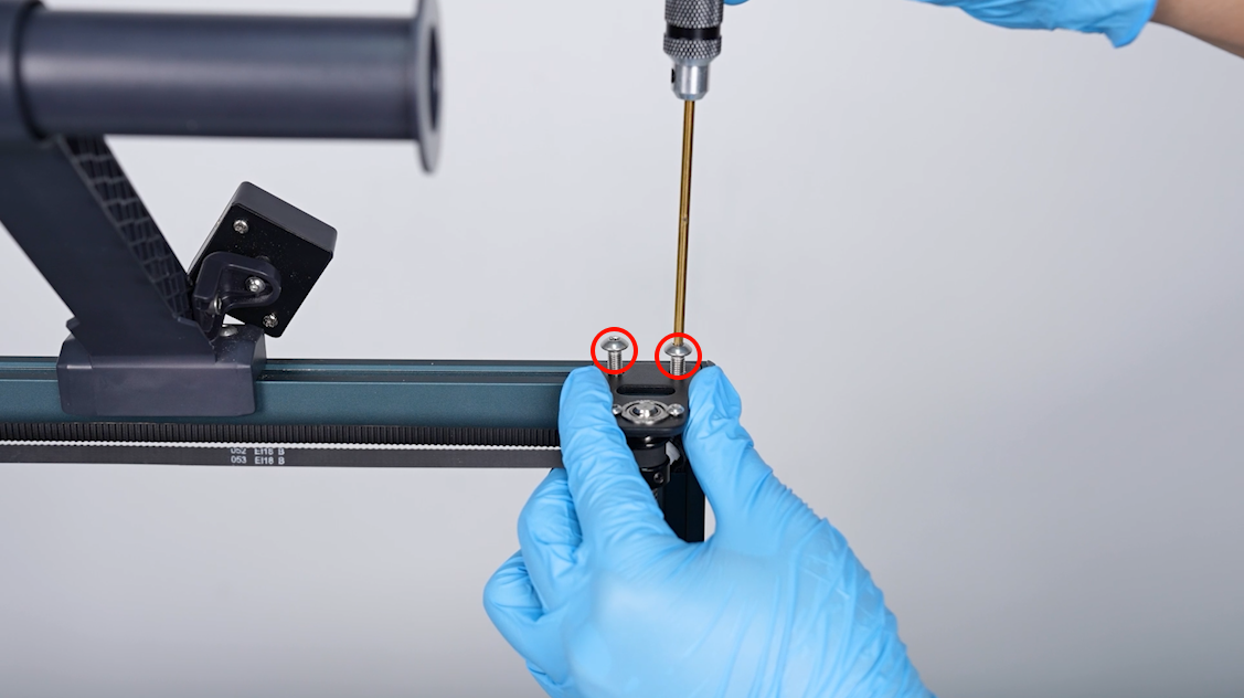
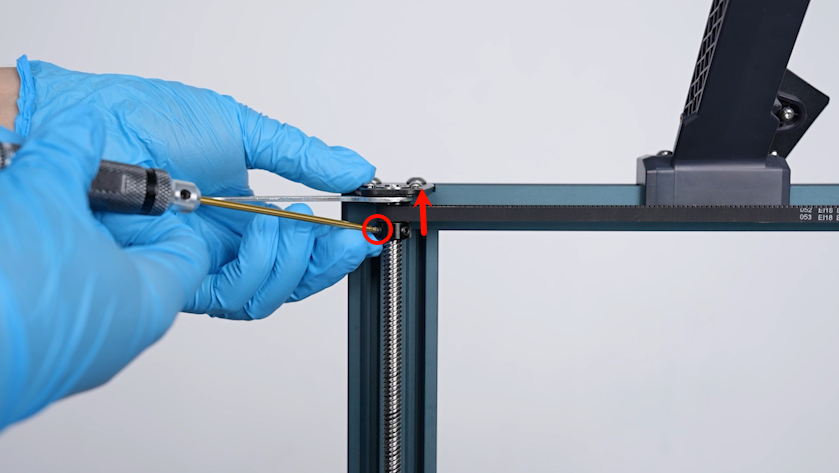
- Loosen the 2 screws securing the timing pulley by one-third of the depth using a 2.0 mm Allen key. Remove the timing belt.
- Remove the other timing pulley in the same way.
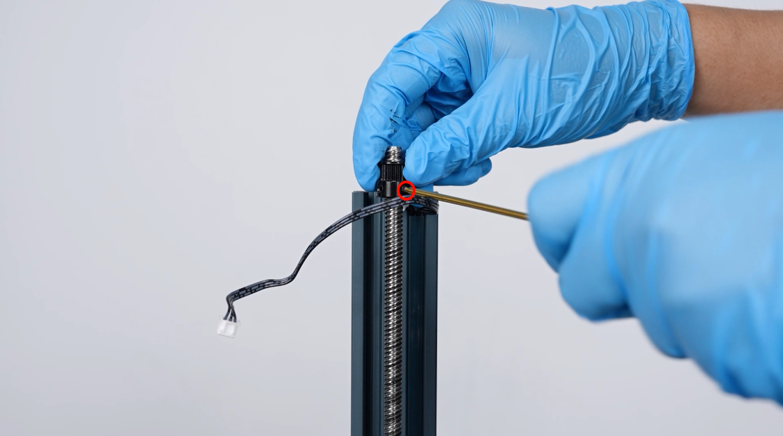
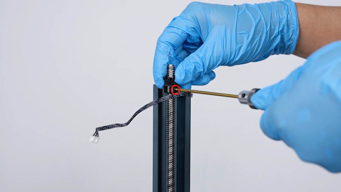
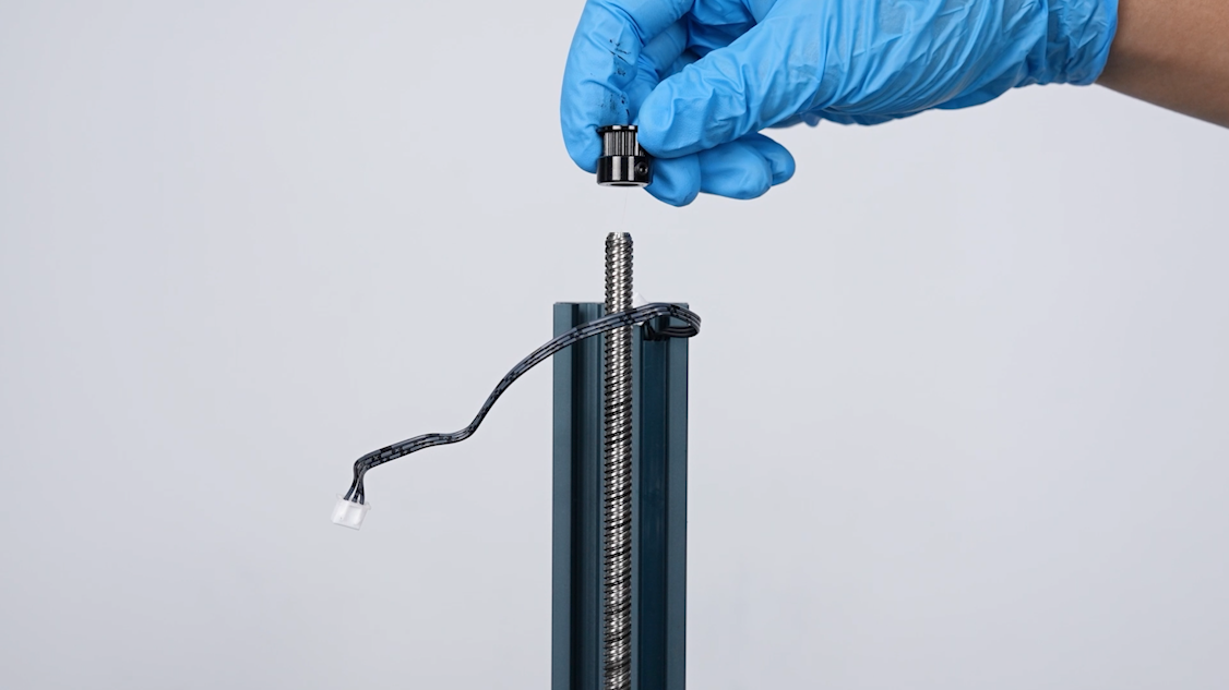
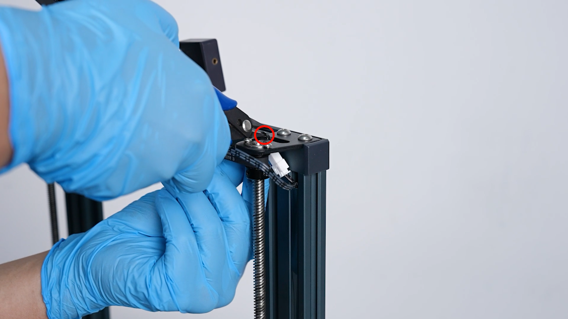
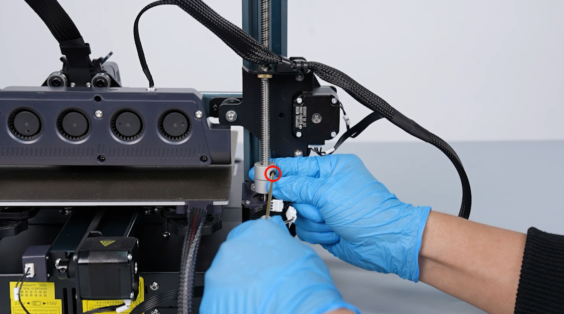
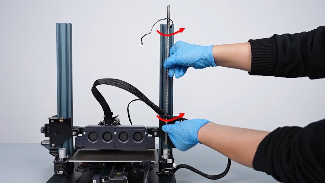
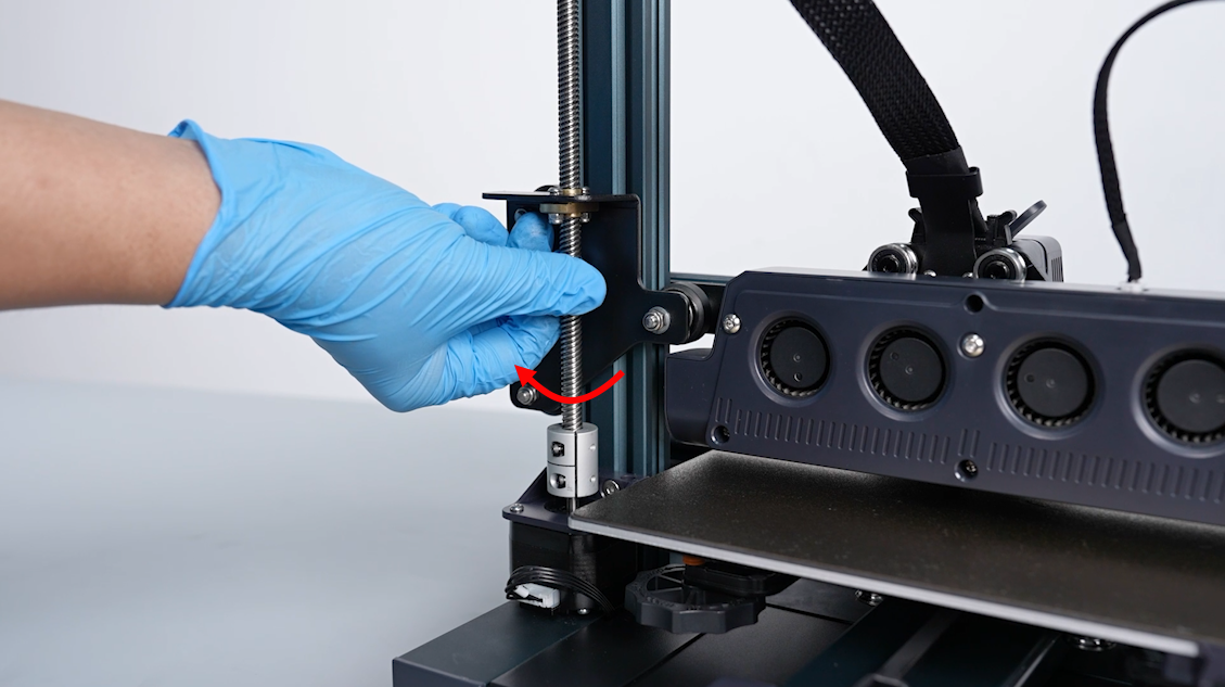
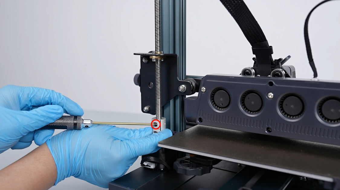
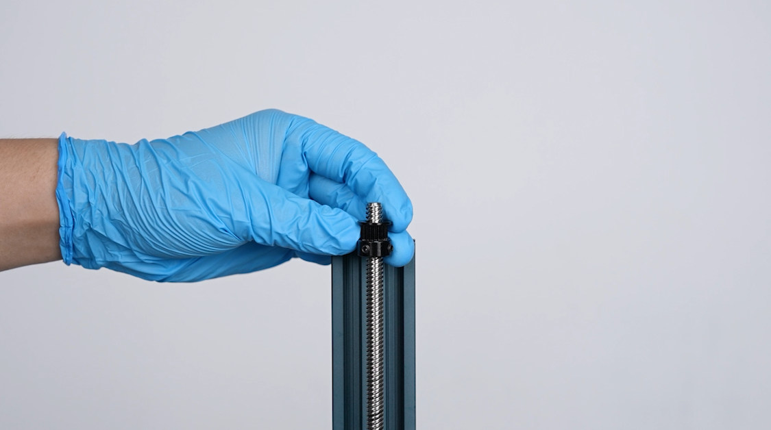
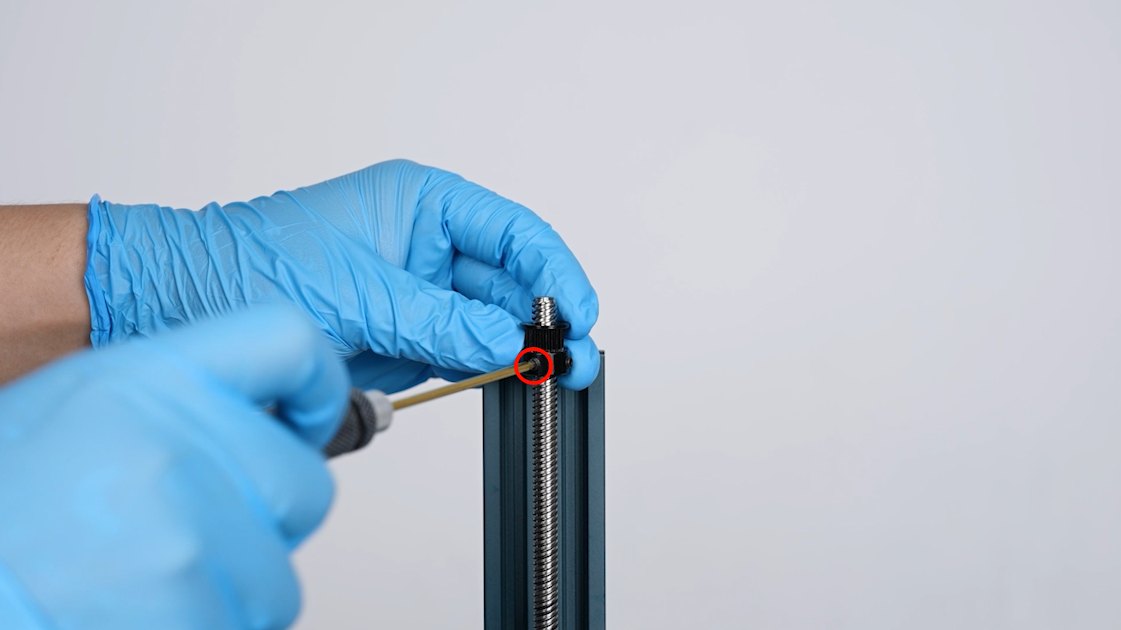
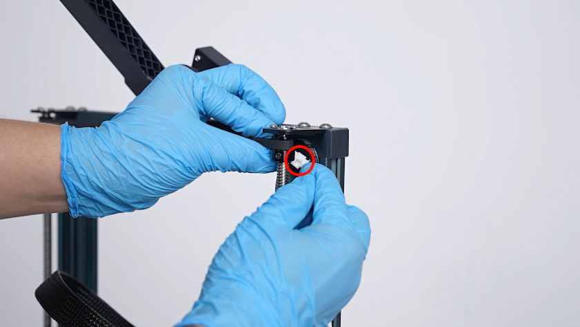
- Loosen the screw securing the lead screw above the coupling using a 2.5 mm Allen key. Rotate the lead screw counterclockwise and remove the lead screw.
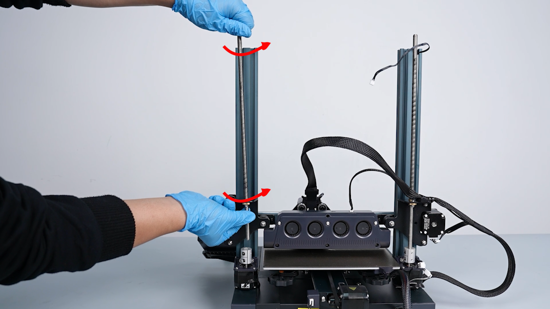
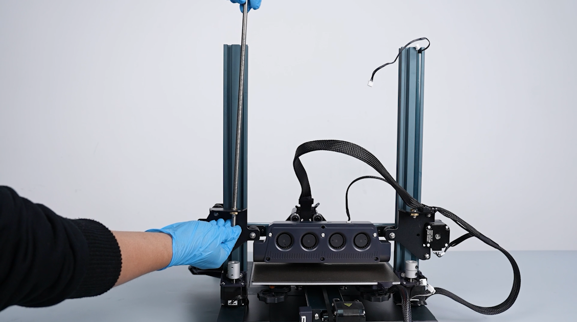
- Remove the other lead screw in the same way.
¶ Install the new lead screw
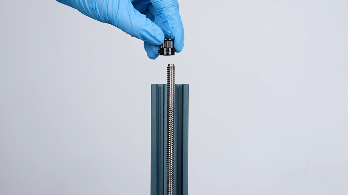
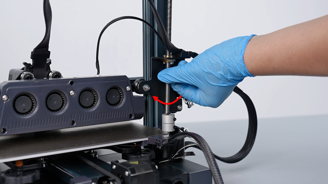
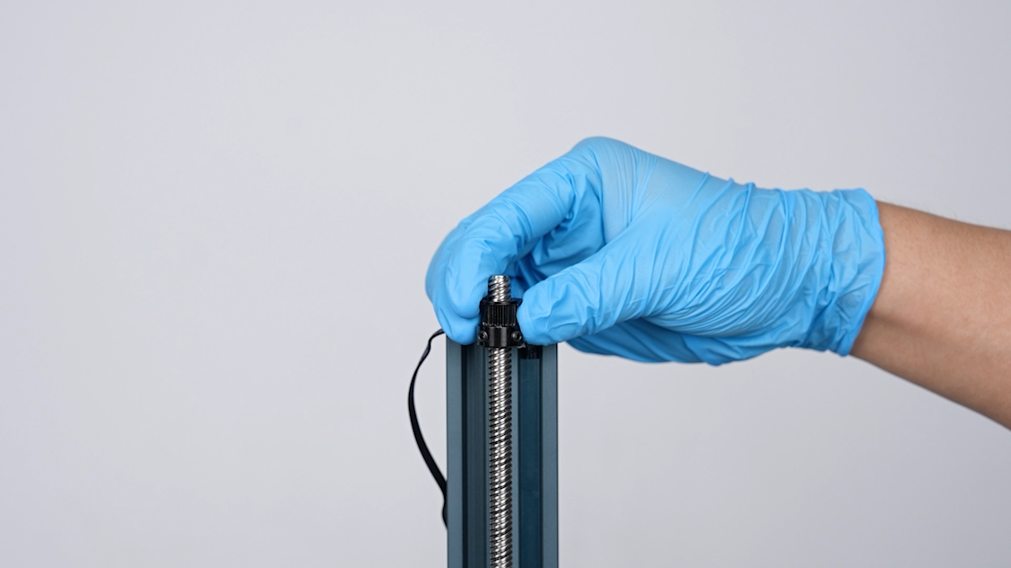
- Prepare the new lead screw. Align the lead screw with the coupling and lead screw nut. Rotate the lead screw clockwise to put it in the installation position.
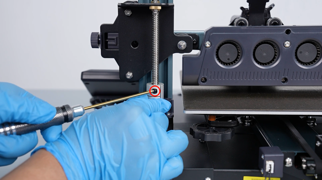
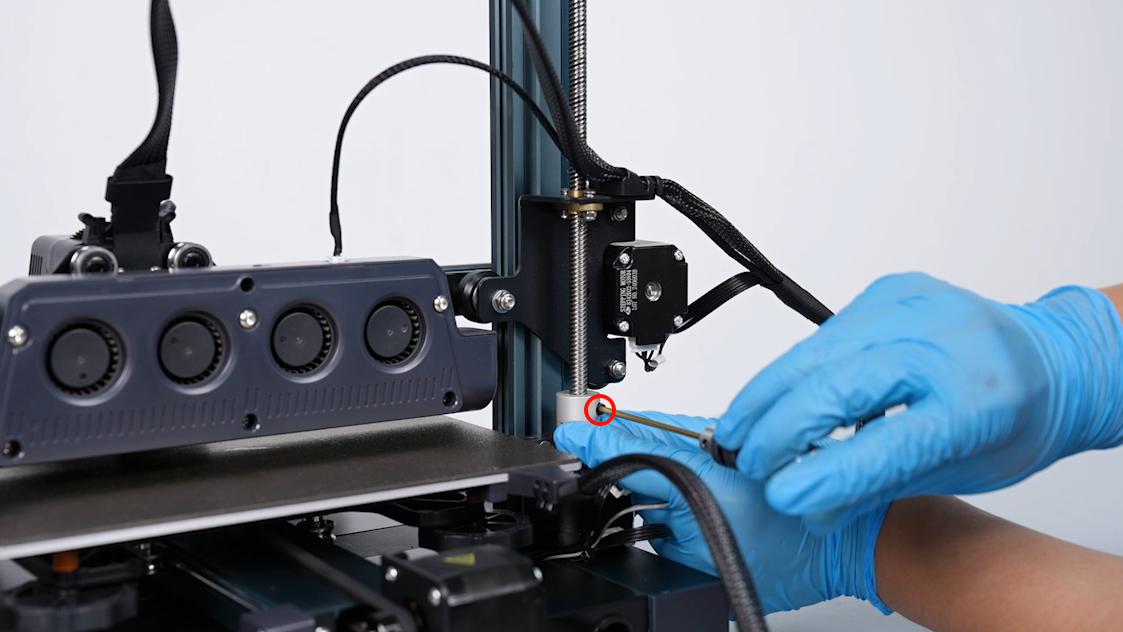
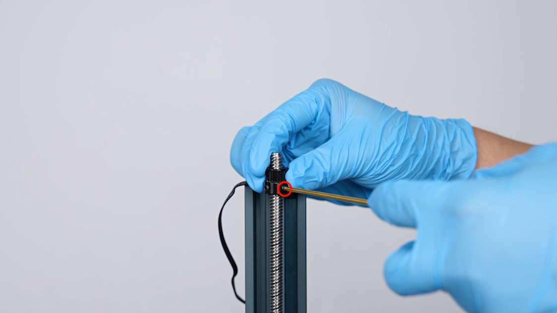
- Tighten the screw securing the lead screw above the coupling using a 2.5 mm Allen key.
- Install the other lead screw in the same way.
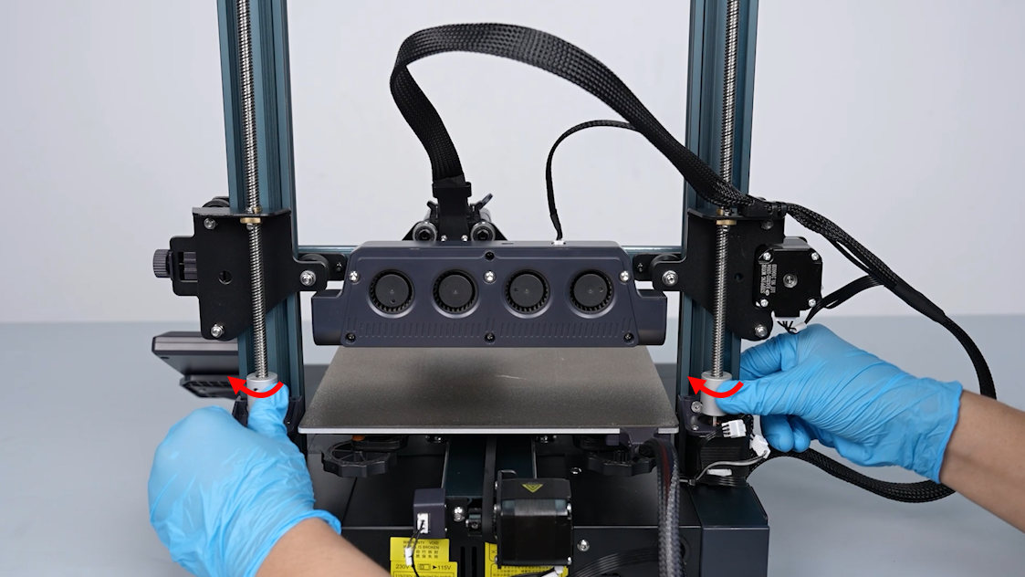
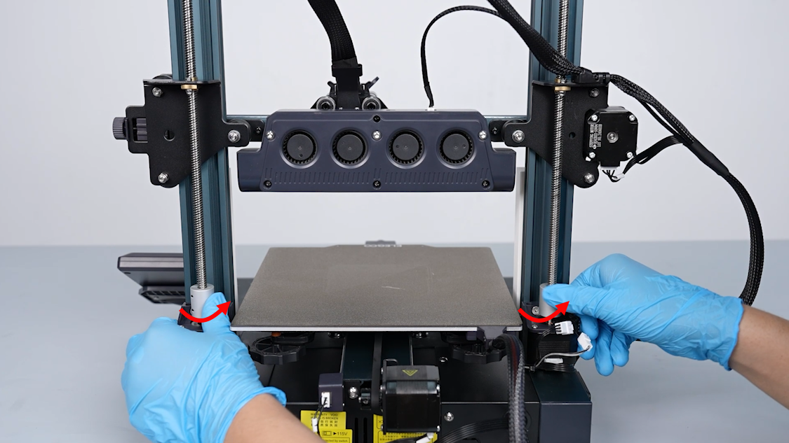
- Rotate both couplings of the lead screw simultaneously and raise the Z-axis.
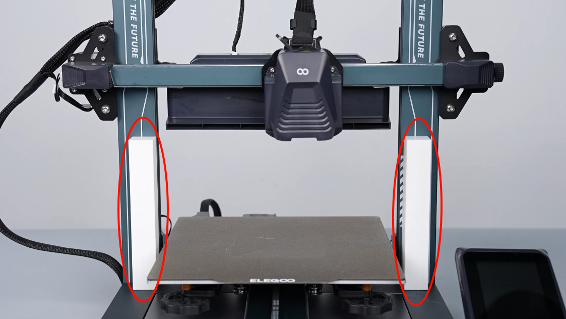
- Put 2 model columns of equal height beneath the X-axis aluminum profile.
Note: It is recommended that the height of the two columns be higher than 120 mm.
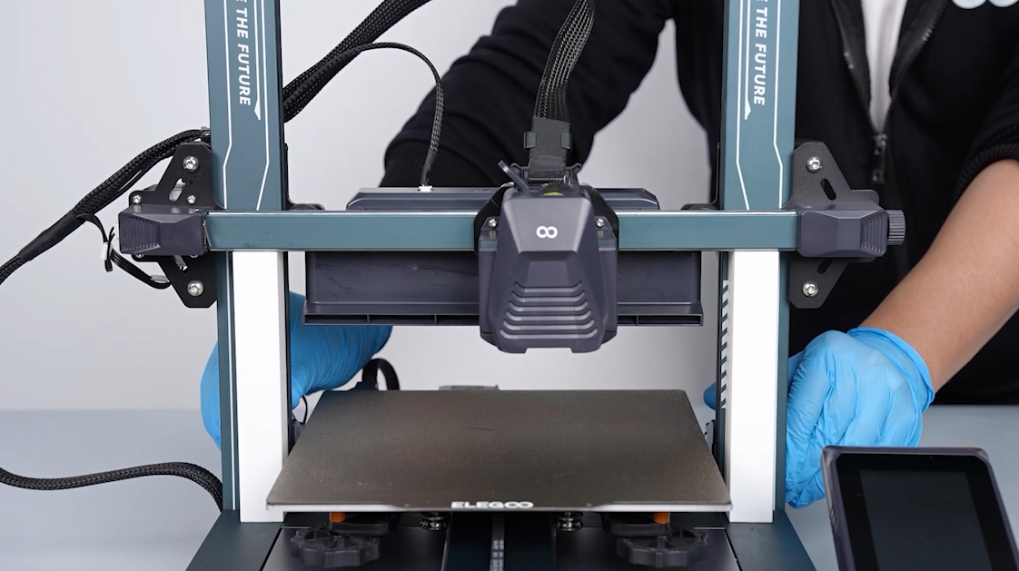
- At the back of the printer, rotate both Z-axis couplings simultaneously to adjust the X-axis aluminum profile so that it descends until it makes contact with the tops of both columns.
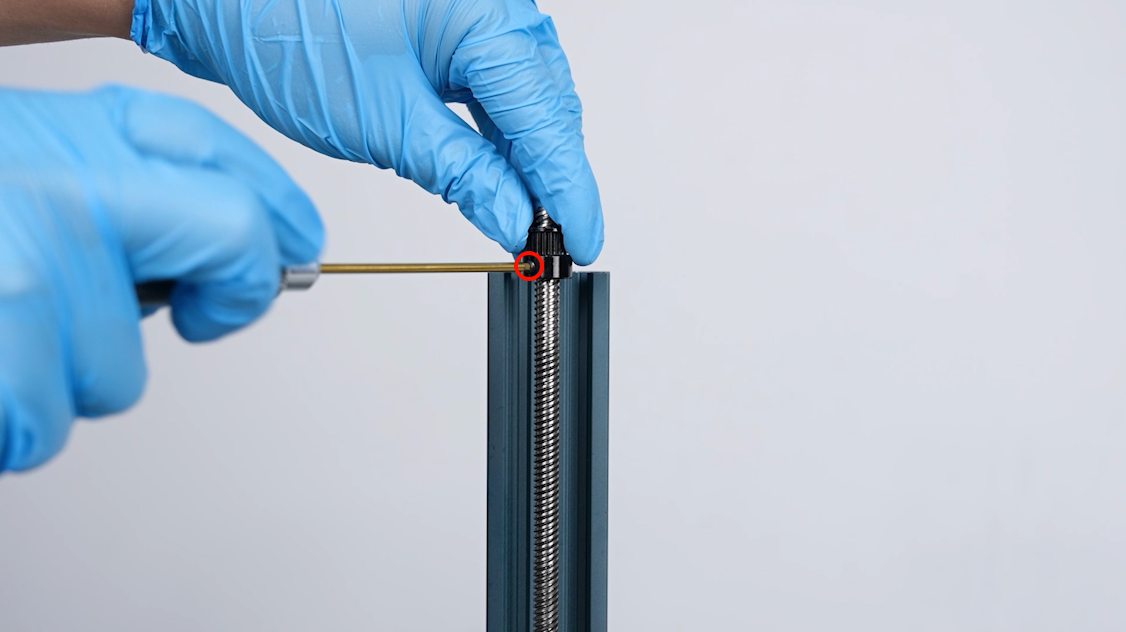
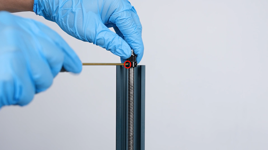
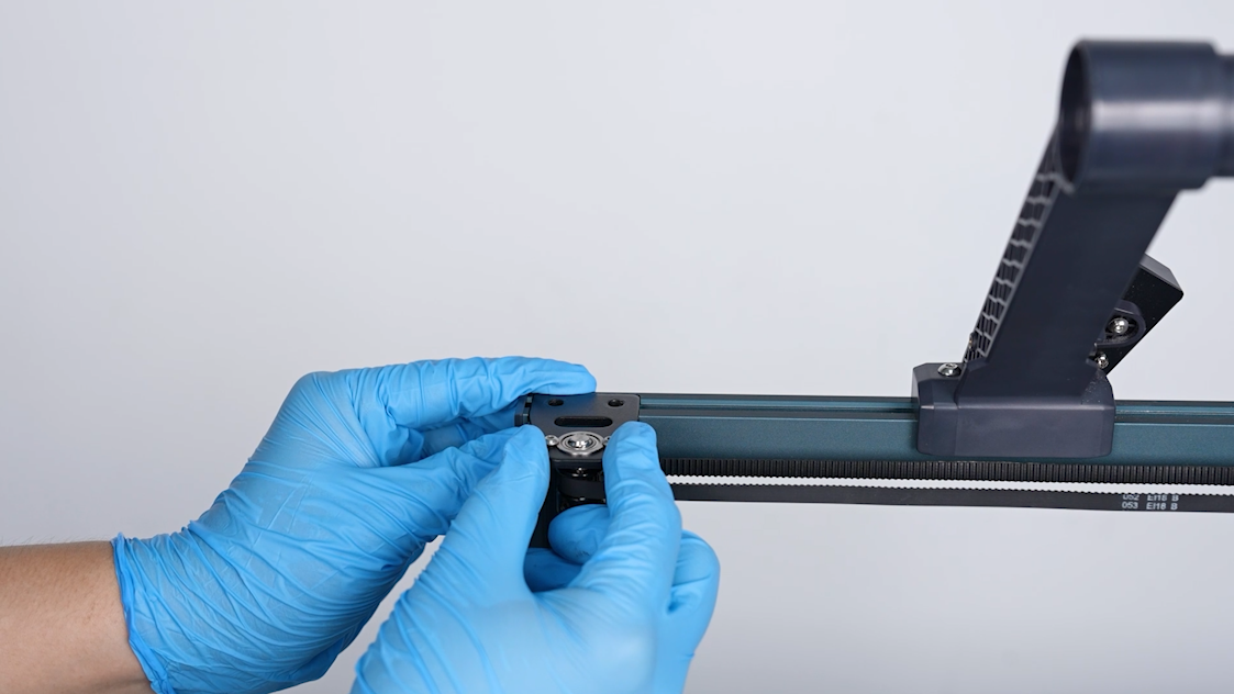
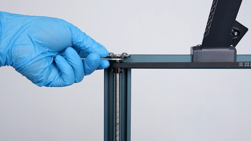
- Align the timing pulley with the lead screw. Put the timing pulley at the top of the lead screw. Tighten the 2 screws securing the timing pulley using a 2.0 mm Allen key.
Note: Install the timing pulley at about 1 cm from the top of the lead screw. Follow-up adjustments can be carried out later.
- Install the timing pulley of the other lead screw in the same way.
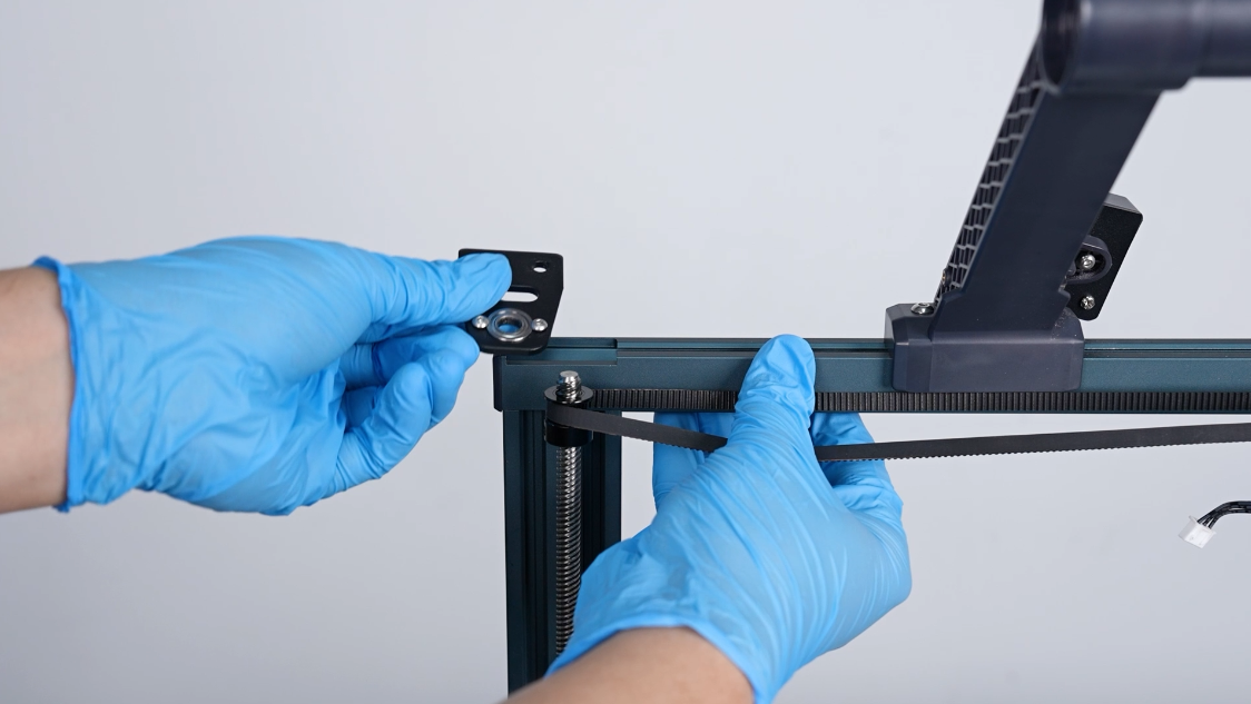
- Install the belt of the timing pulley on the timing pulleys at both sides. Align the aluminum profile on top of Z-axis with the screw holes. Put the aluminum profile on top of Z-axis in the installation position.
Note: Organize the cables of the top light.
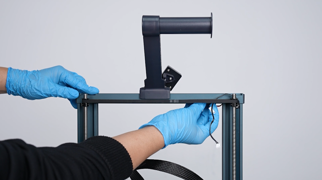
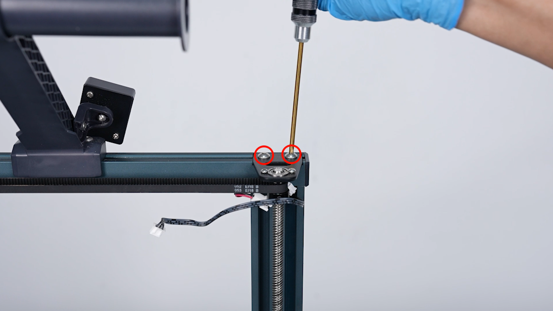
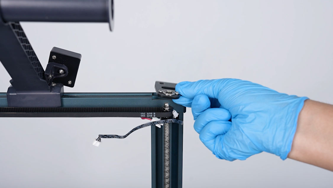
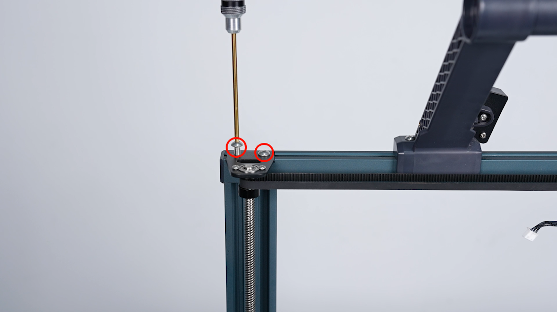
- Align the top fixing plate with the screw holes. Put the top fixing plate in the installation position. Tighten the 2 screws securing the fixing plate using a 3.0 mm Allen key.
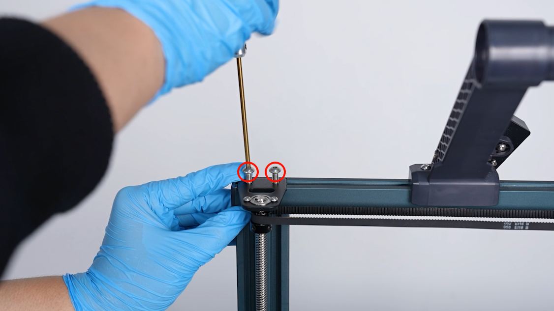
- Install the top fixing plate at the other side in the same way.
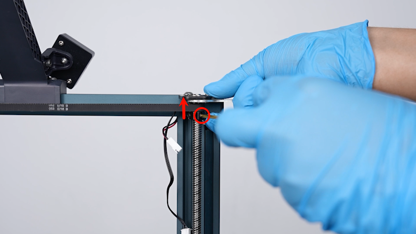
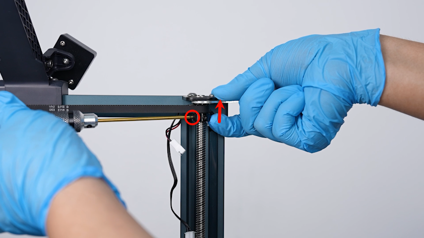
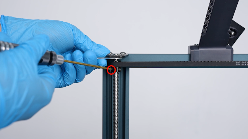
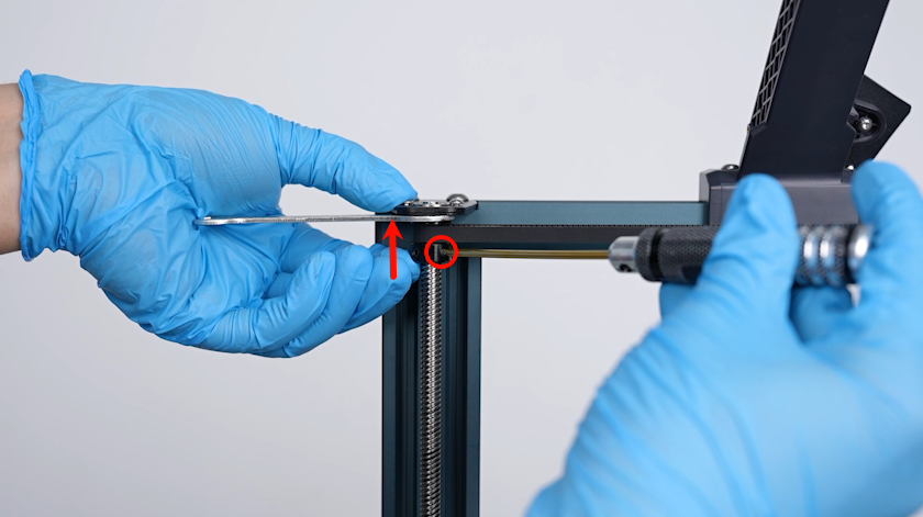
- Put a spanner to secure between the top fixing plate and the timing pulley. Loosen the screws securing the timing pulley using a 2.0 mm Allen key.
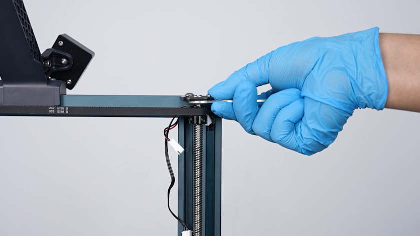
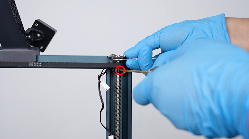
- Press the timing belt towards the spanner and then tighten the 2 securing screw.
Note: Make sure the distance between the top fixing plates and the timing pulley on both sides of the Z-axis is same.
- Adjust the other timing pulley in the same way.
- Insert the top light cable port. Thread the cables of the filament runout detection through the fixing plate at the top of the lead screw and insert the filament runout detection.
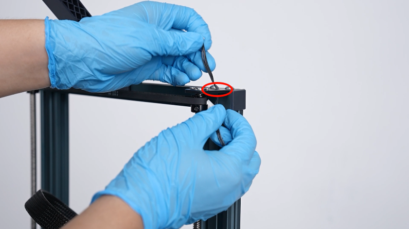
- Organize the cables of the filament runout detection and put the cables into the groove s of the aluminum profile. Secure the cables on the top fixing plate using zip ties.
- Pull the timing belt above the Z axis and raise the Z axis. Remove the two coloums below the X-axis aluminum profile.
¶ Lubricate the new lead screw
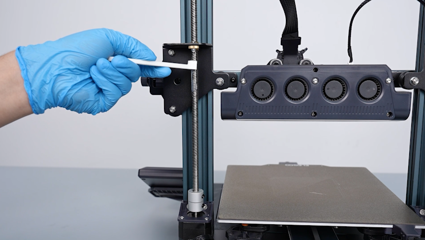
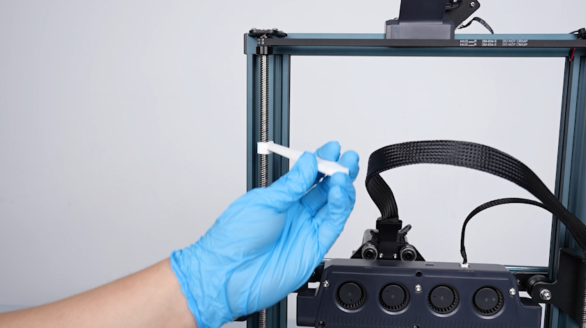
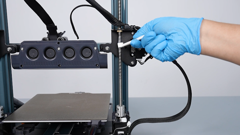
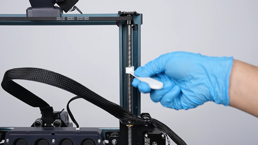
- Apply new grease to both sides of the lead screw.
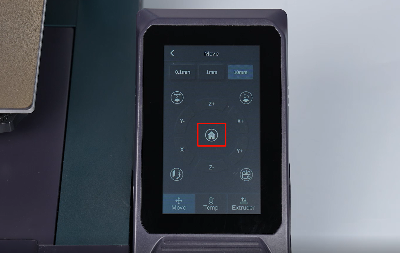
- Power on the printer. Select Prepare - All (Homing) on the touchscreen. The printer starts homing process.
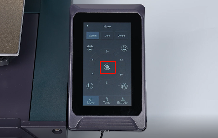
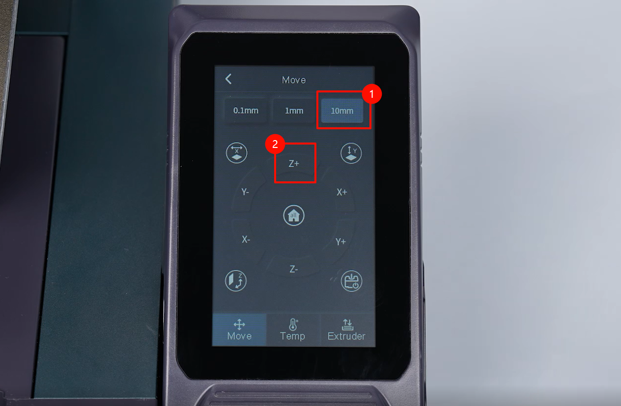
- Select "10 mm" distance and tap "Z-axis" to raise the Z-axis. Raise the print head to the top.
- Select "Z-axis Homing" and the printer starts the homing process to make the grease applied evenly.
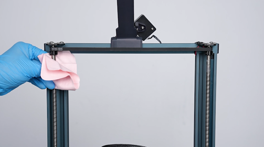
- Clean the excess grease accumulated at the ends of the lead screws.
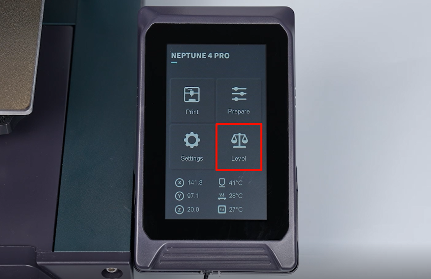
¶ Level the printer
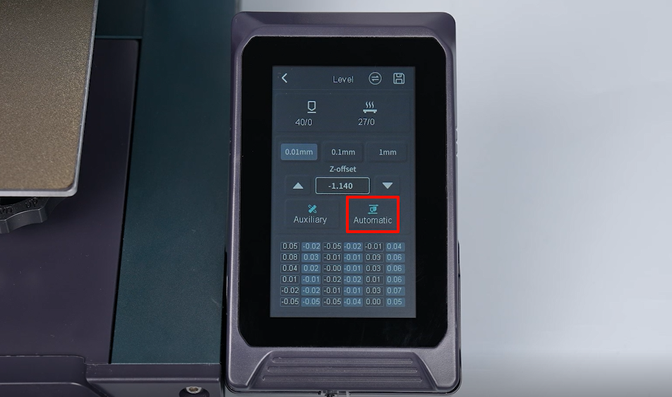
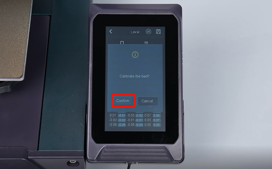
- Select Level on the touchscreen. The printer starts homing process.
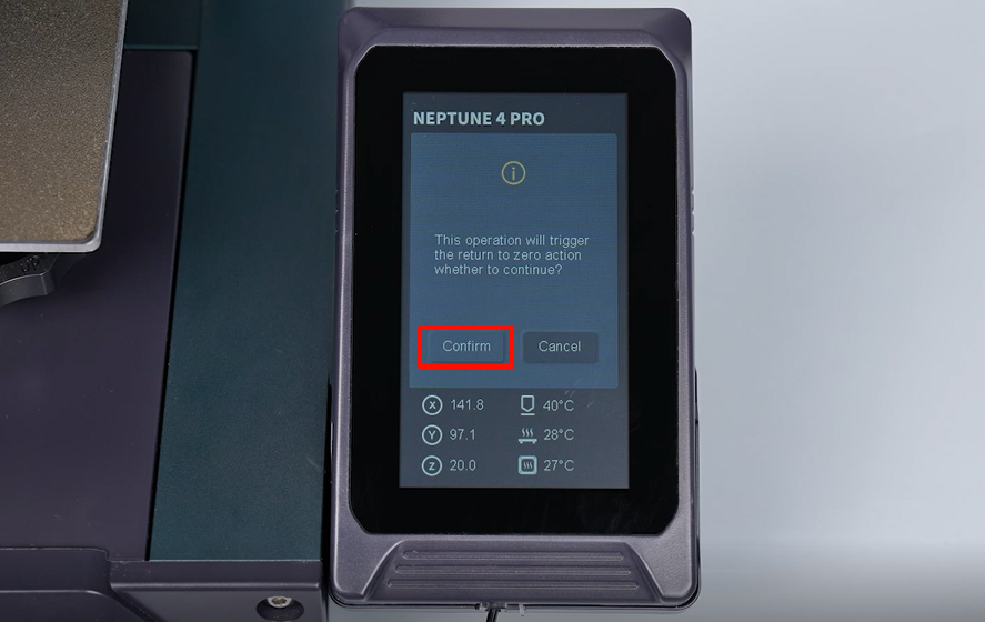
- After entering into the leveling interface, select "Auto leveling -Confirm" The printer is ready for use after leveling.