Model Orientation and Support Generation in CHITUBOX
Introduction
The level of surface refinement for resin 3D-printed models can vary a lot depending on factors such as model orientation and the support structures used. This article discusses how to adjust the model orientation and create supports effectively.
Operating Steps
¶ Determining the Optimal Model Orientation
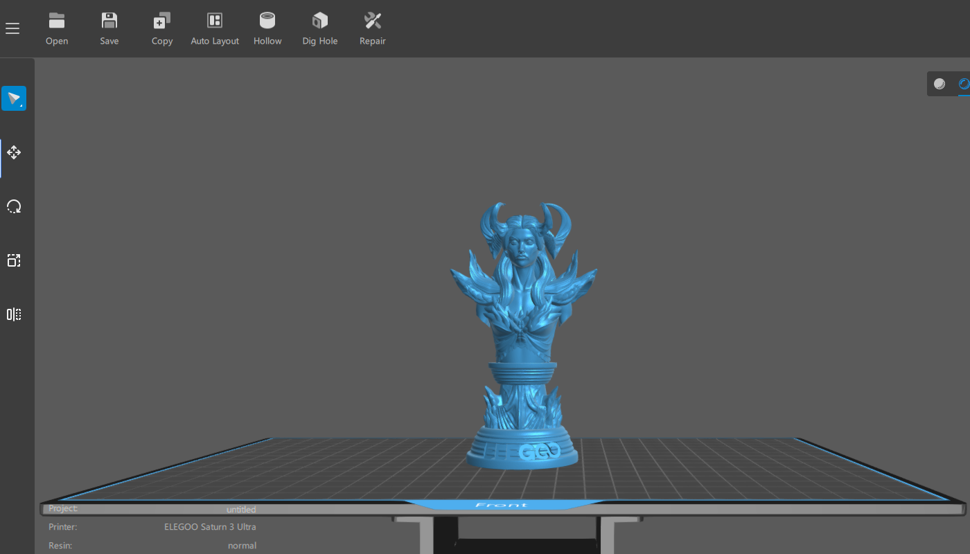
- After importing the model, right-click and drag the model to rotate and observe it from different angles. Seek to identify the optimal printing orientation and proceed to create supports to ensure a successful print.
|
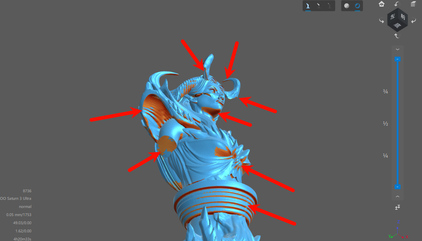
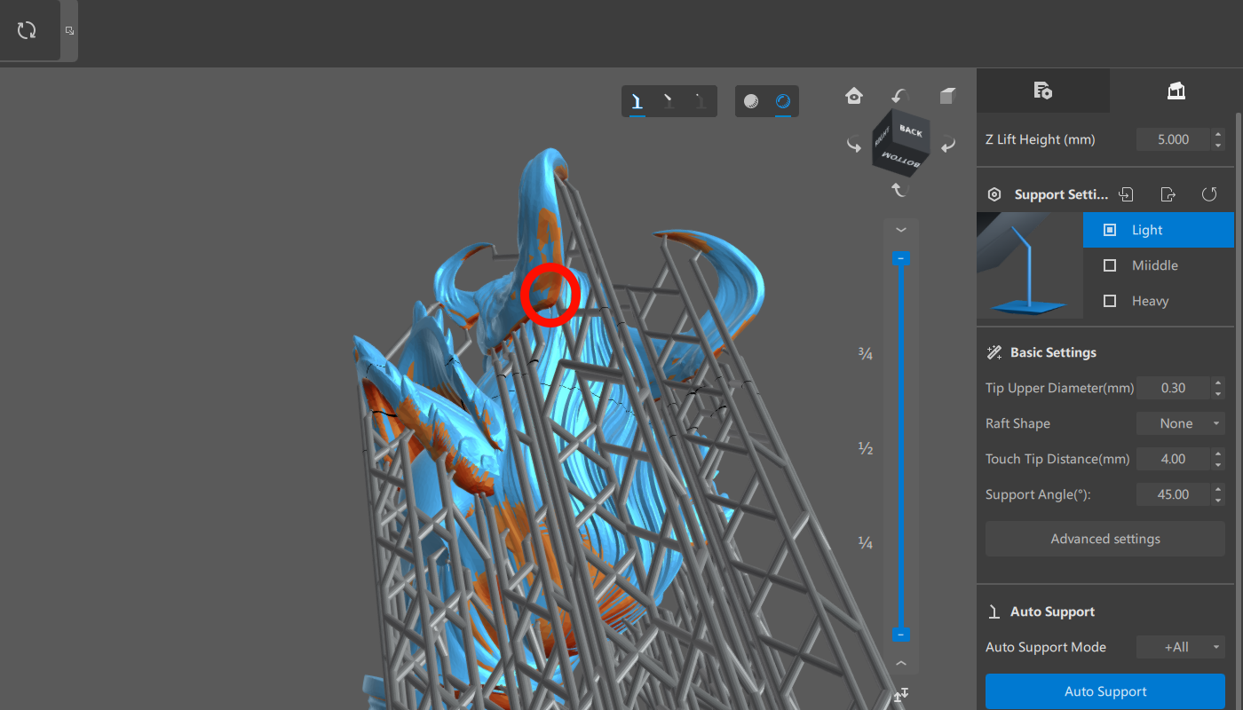
- When adjusting the model’s angle, rotate the perspective to observe the overhangs when the model is placed flat.
(Tip: You can open the support generation page, and the software will mark the overhangs. The red shaded parts at the arrow markings indicate the unsupported areas of the model.)
|
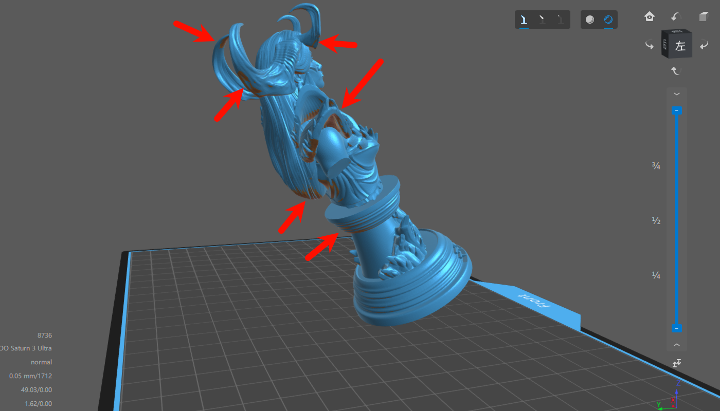
- Since excessive supports can make it difficult to handle intricate details on the front of the model, it is recommended to tilt the model backward. To find the optimal placement, consider rotating it to different angles (e.g., 30°, 45°, 60°) and compare the support requirements for each angle.
(Note: The recommended model orientation is typically 45°. However, for complex models, the optimal orientation may vary. Prioritize avoiding excessive supports that could potentially obscure or cover up important features of the model.)
Model placement angle: 30° |
|
¶ Hollowing and Digging Holes
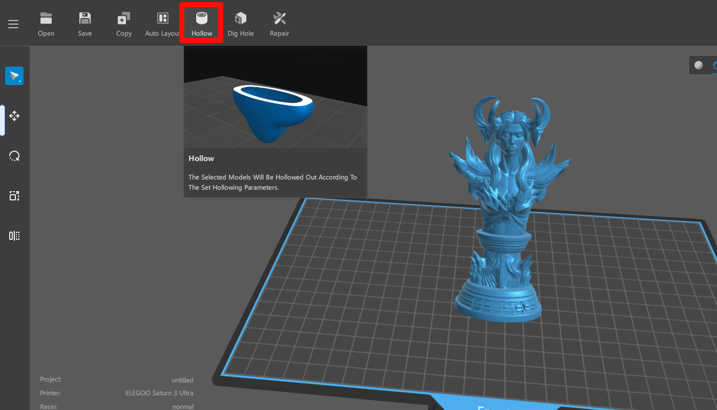
- To handle large-sized models during the angle adjustment, hollowing is necessary. Select the model and click the “Hollow” button in the toolbar. Start the hollowing process after adjusting the parameters based on the model's specific characteristics. Drag the layer slider to observe the resulting hollowing effect.
(Note: The typically recommended wall thickness for hollowing is 2-3mm.)
|
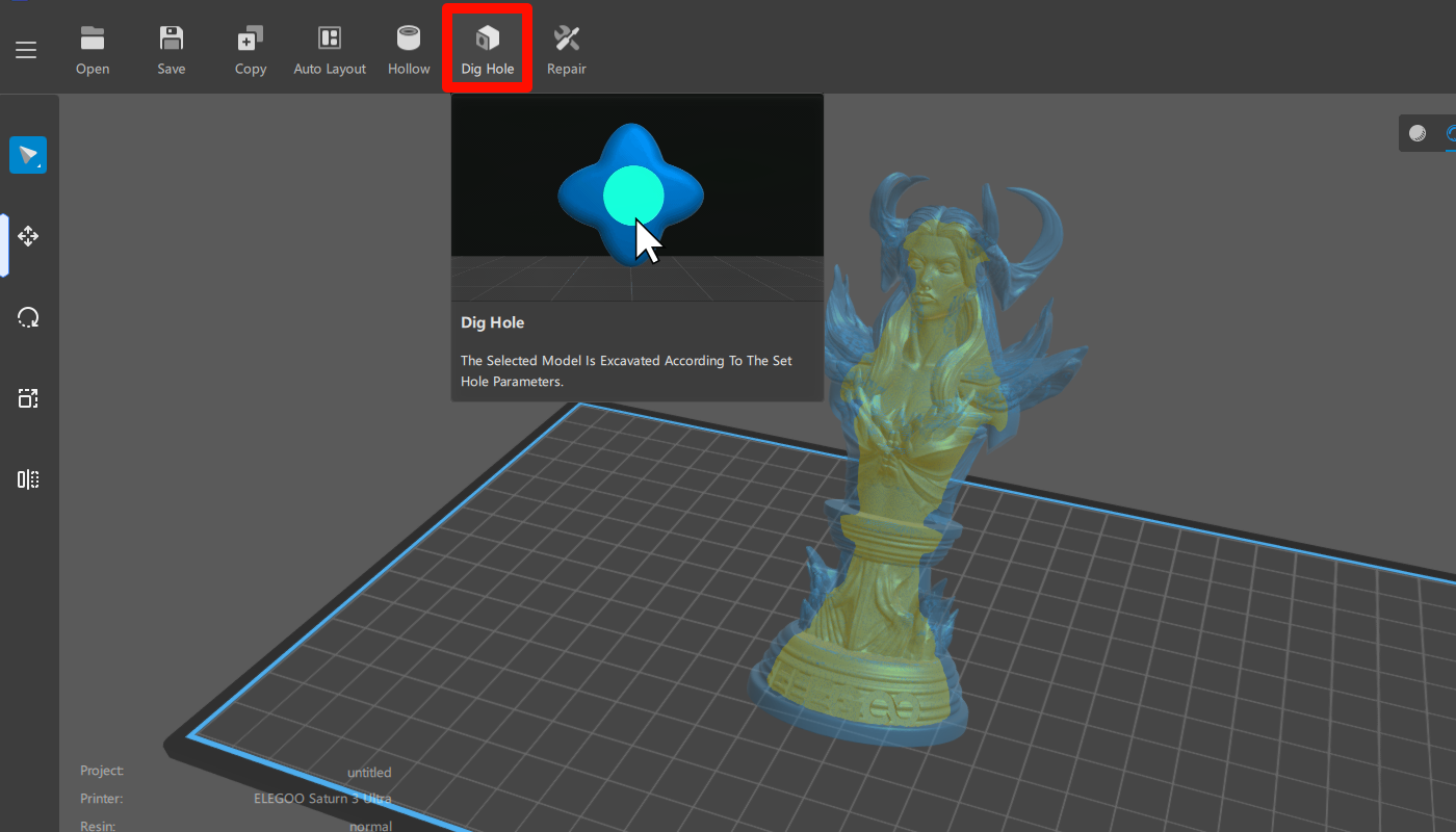
- After hollowing the model, it is necessary to dig holes, ideally with a diameter between 2-5mm. Carefully select their placement for easy post-processing, internal resin cleaning, and effective alcohol drainage. It is recommended to position the holes near the bottom of the model, closest to the build plate. To prevent a vacuum environment, make sure to dig two or more holes, taking care not to affect the surface features.
(Note: This step is necessary to facilitate proper cleaning of the internal resin and avoid potential cracks during prolonged storage.)
|
¶ III. Modifying and Adding Support Parameters
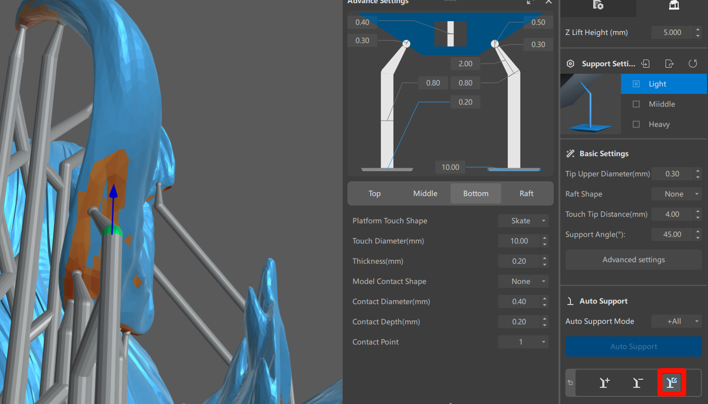
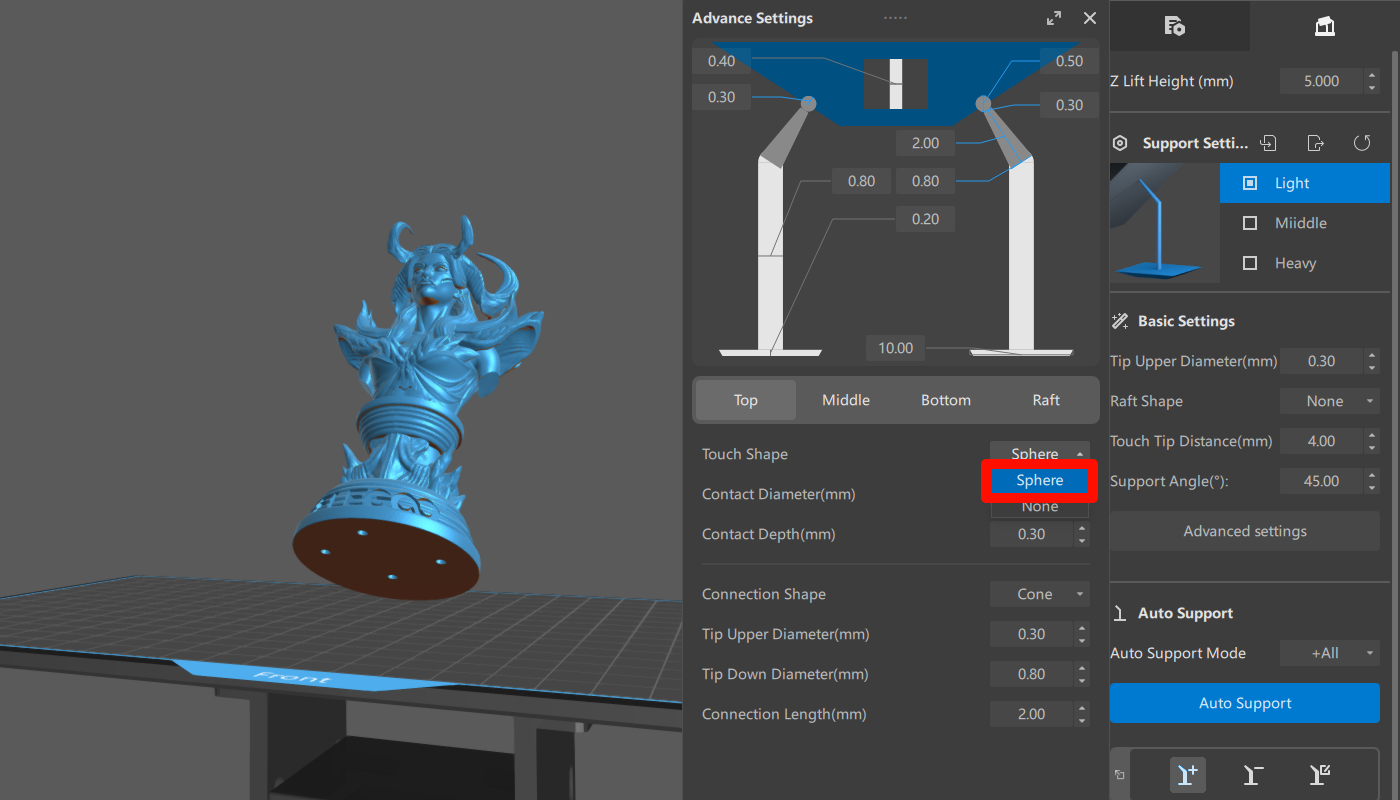
- In the support parameters, select the sphere touch shape for the top part of the support. It is recommended to keep the support bottom or raft thickness below 0.2mm. Maintaining the height of the support bottom or raft below 0.2mm can enhance the success rate of model printing.
(Note: Not setting the touch shape may result in holes in the support locations after removal. Sphere supports will leave a small protrusion, facilitating post-processing and polishing.)
|
- Rotate the model to inspect for unsupported overhangs. Due to the gap between the build platform and the LCD screen caused by the printed section, unsupported overhanging areas may adhere to the release film and fail to detach properly.
(Note: Insufficient support in overhanging areas can lead to print failures.)
|
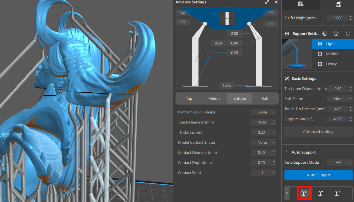
- Add Support (A): Add supports to the model's overhangs.
|
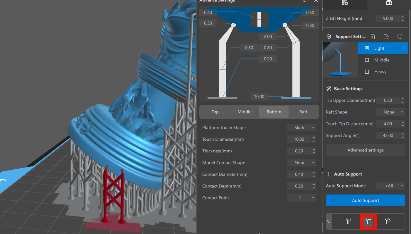
- Delete Support (D): Remove excessive supports. Click on the command to delete the desired support.
|
- Edit Support (E): This command enables support movement and editing when dealing with overhanging areas that require multiple supports. Double-click on the tail end of a support to create a new support branching out from that position.
|