¶ Tools and materials needs to prepare
- 2.0 mm Allen wrench
- 2.5 mm Allen wrench
- 3.0 mm Allen wrench
- diagonal cutting pliers
- label ties
- Cotton swabs
- Lubricant
¶ Reference Video
¶ Operation Steps
¶ Power Off the Printer and Remove the Rear Cover
-
Turn off the 3D printer power and unplug the power cable.
-
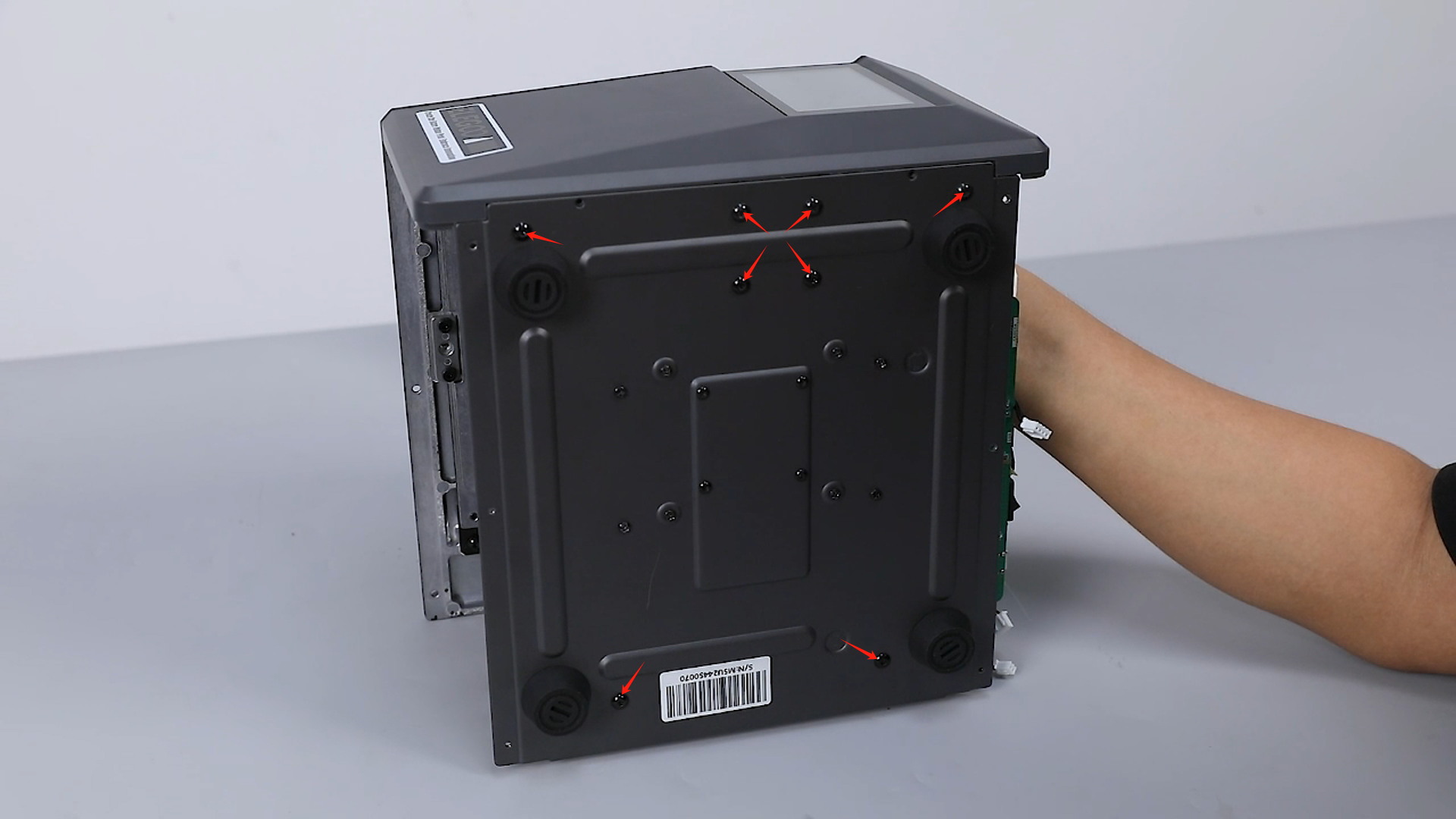
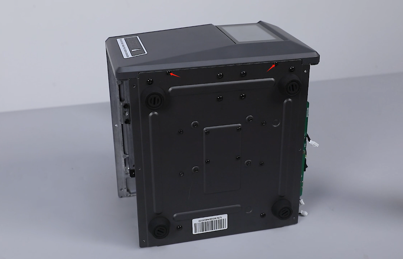
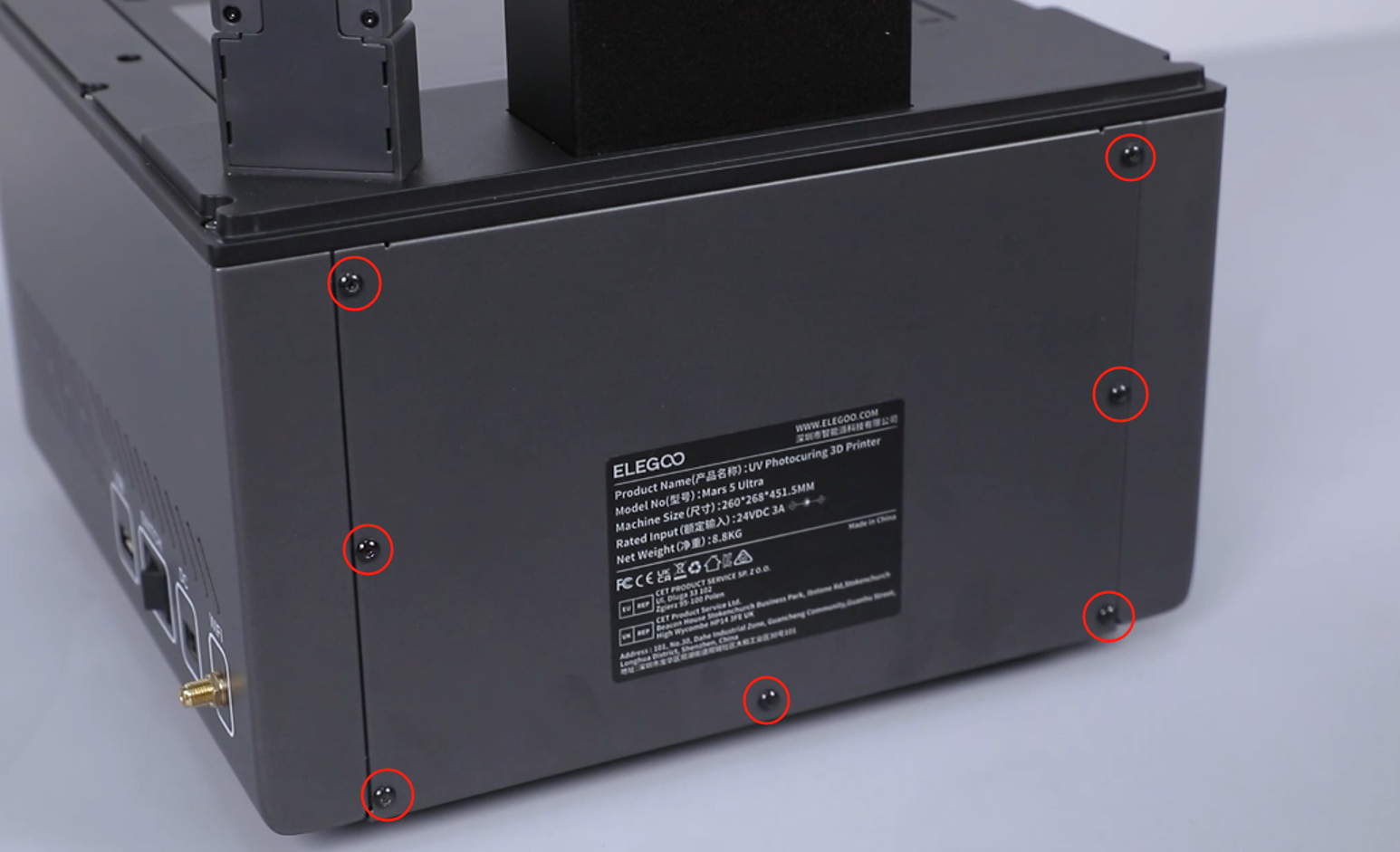
Loosen 7 screws securing the 3D printer rear cover using a 2.0 mm Allen wrench, and remove the rear cover.

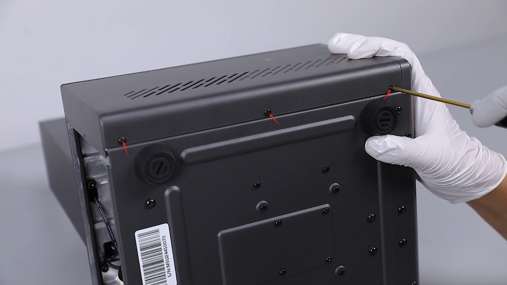
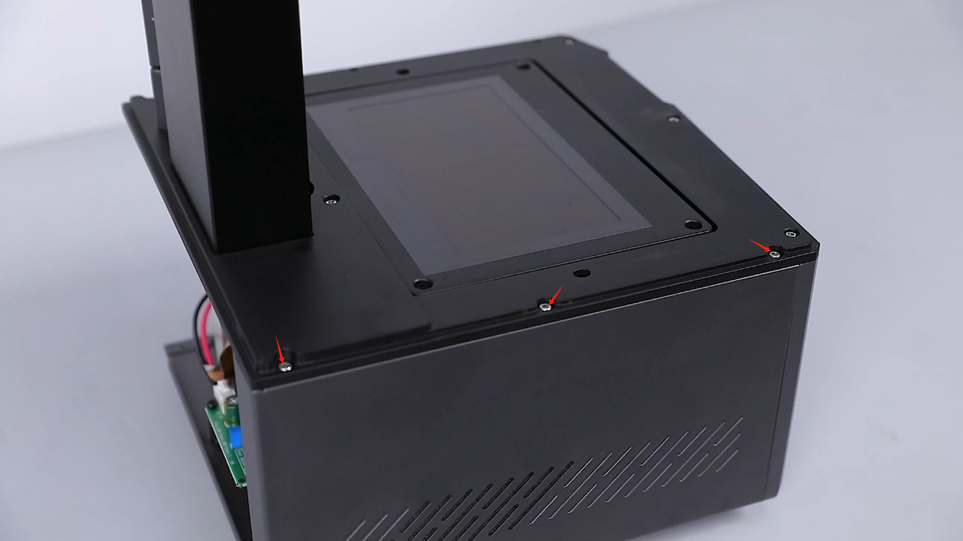
¶ Remove the Right Cover and Disconnect the Wi-Fi Ribbon Cable
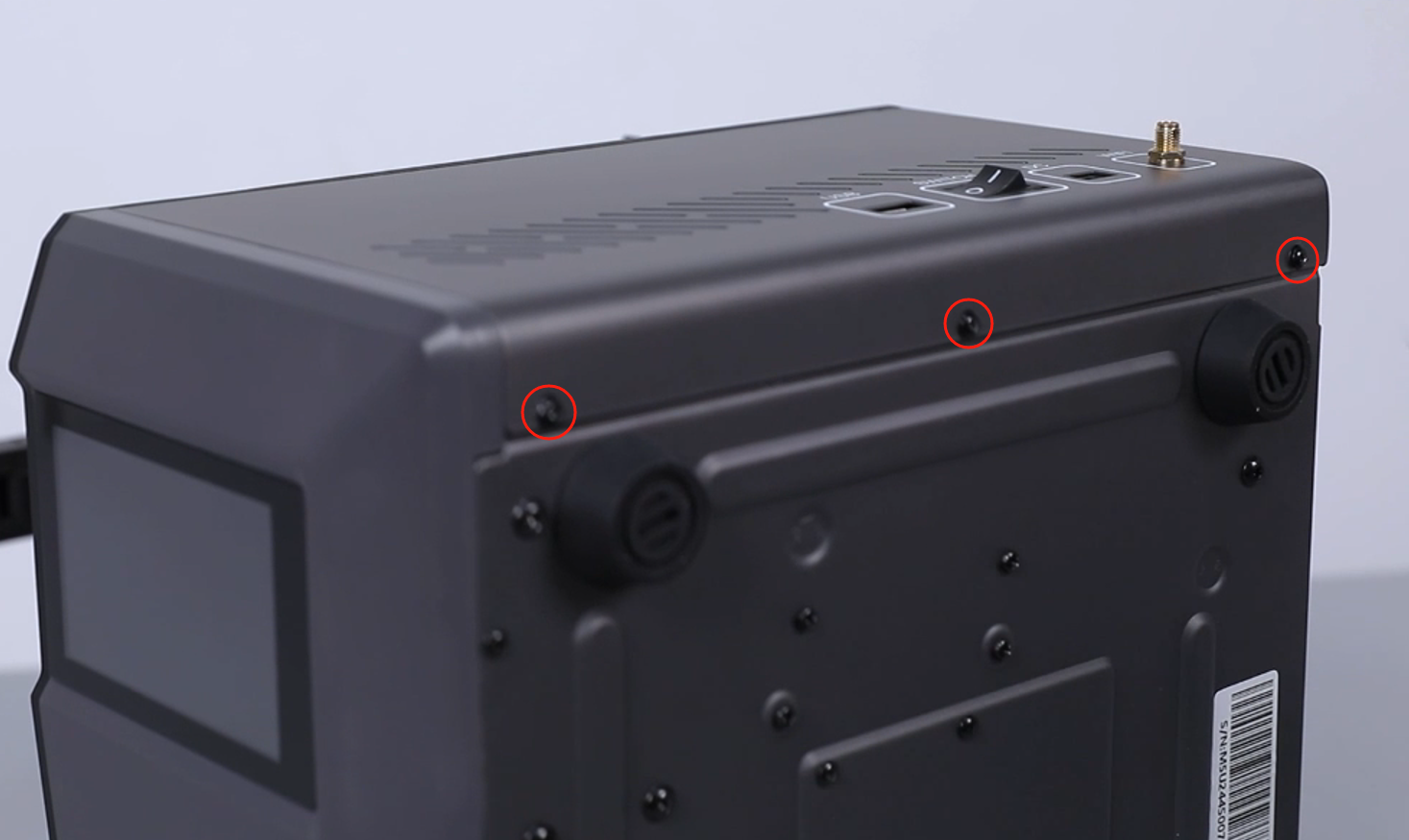
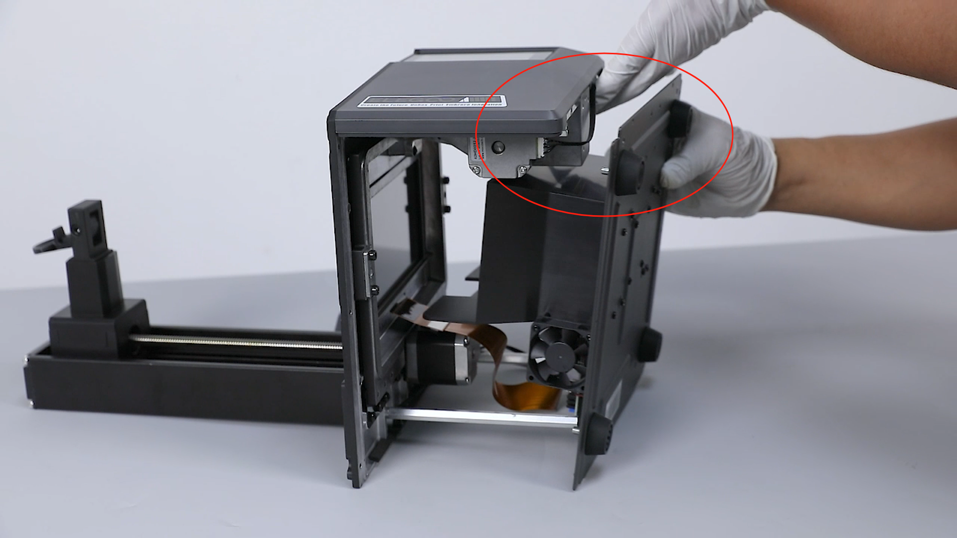
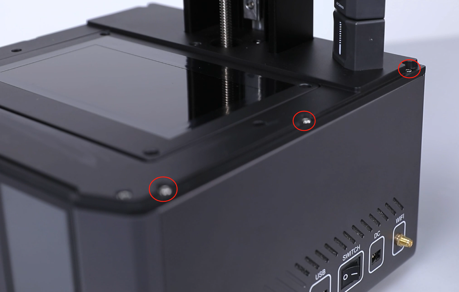
- Loosen 3 screws securing the top of the right cover using a 2.5 mm Allen wrench.

- Loosen 3 screws securing the top of the right cover using a 2.5 mm Allen wrench.
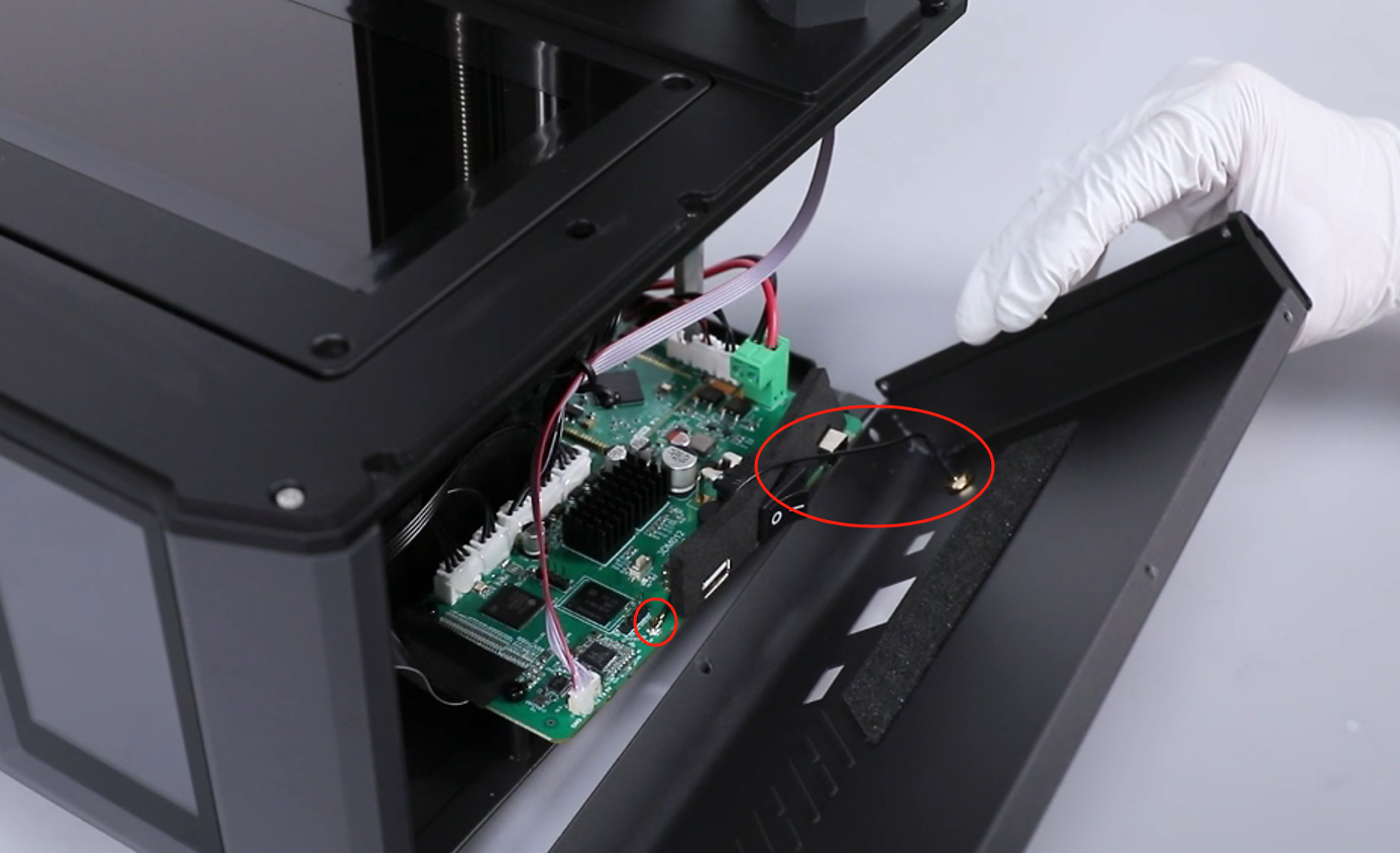
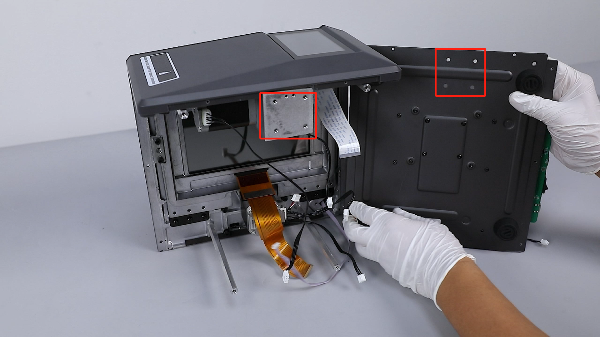
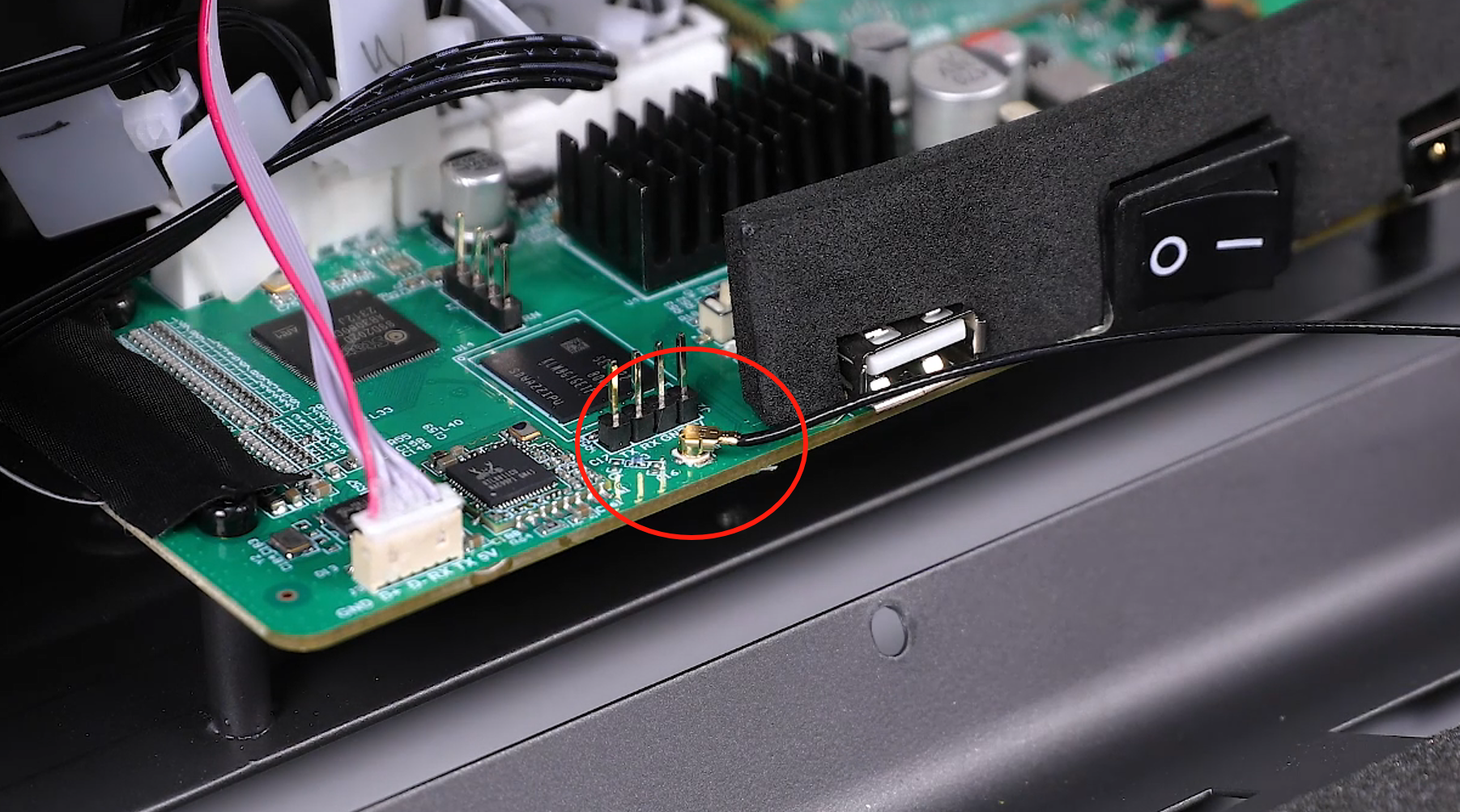
- There are wifi ribbon cables connected internally. Slowly open the right cover, unplug the wifi ribbon cable from the motherboard port, and remove the right cover.
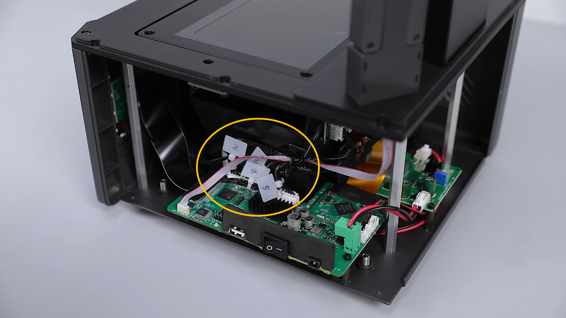
¶ Label the Internal Ribbon Cables
- Use label ties or label paper to mark each ribbon cable on the motherboard and interface board.

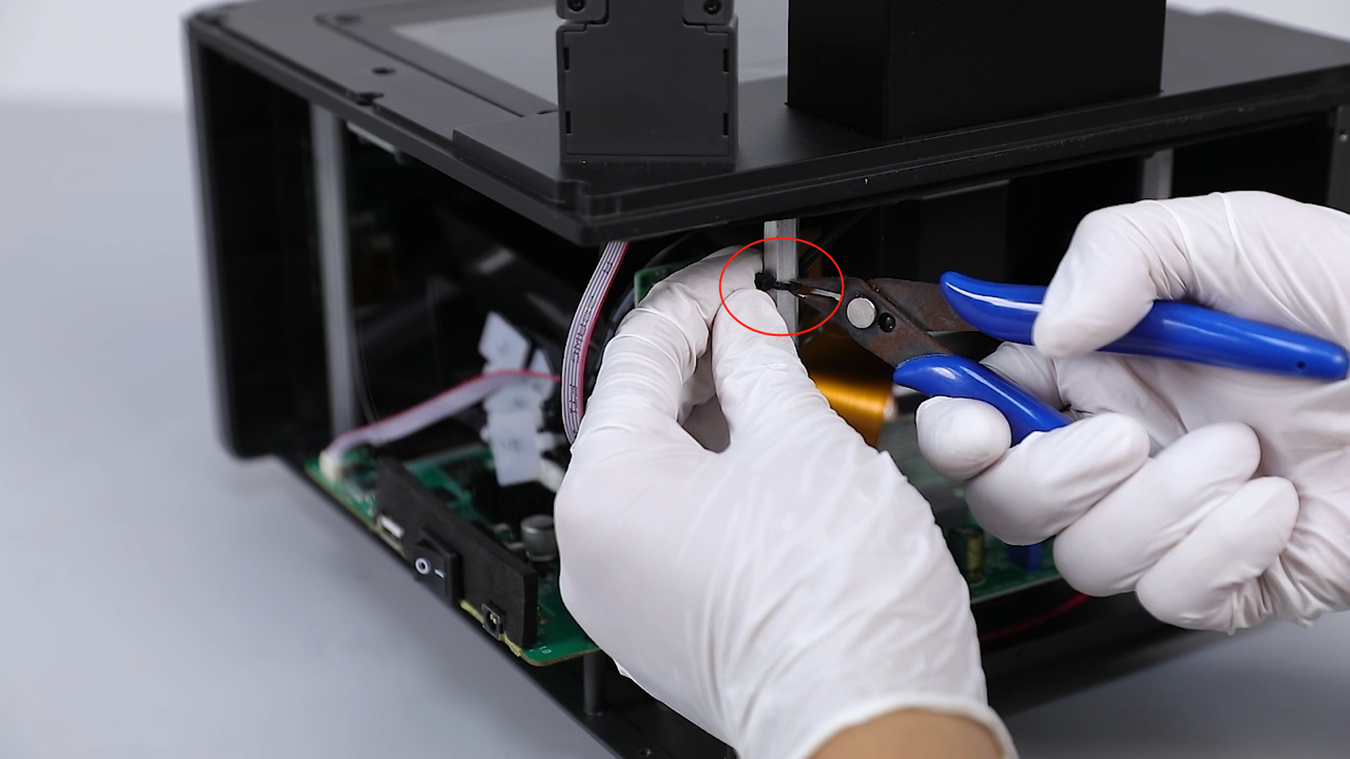
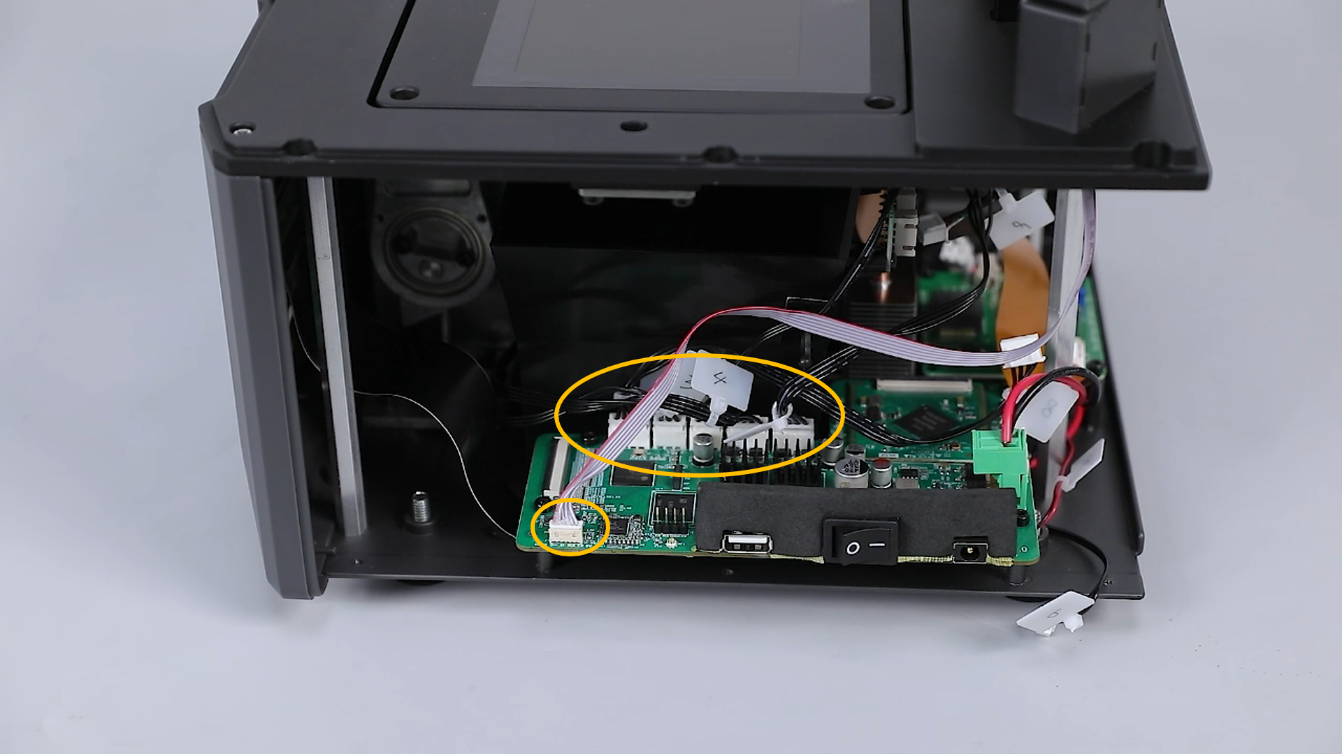
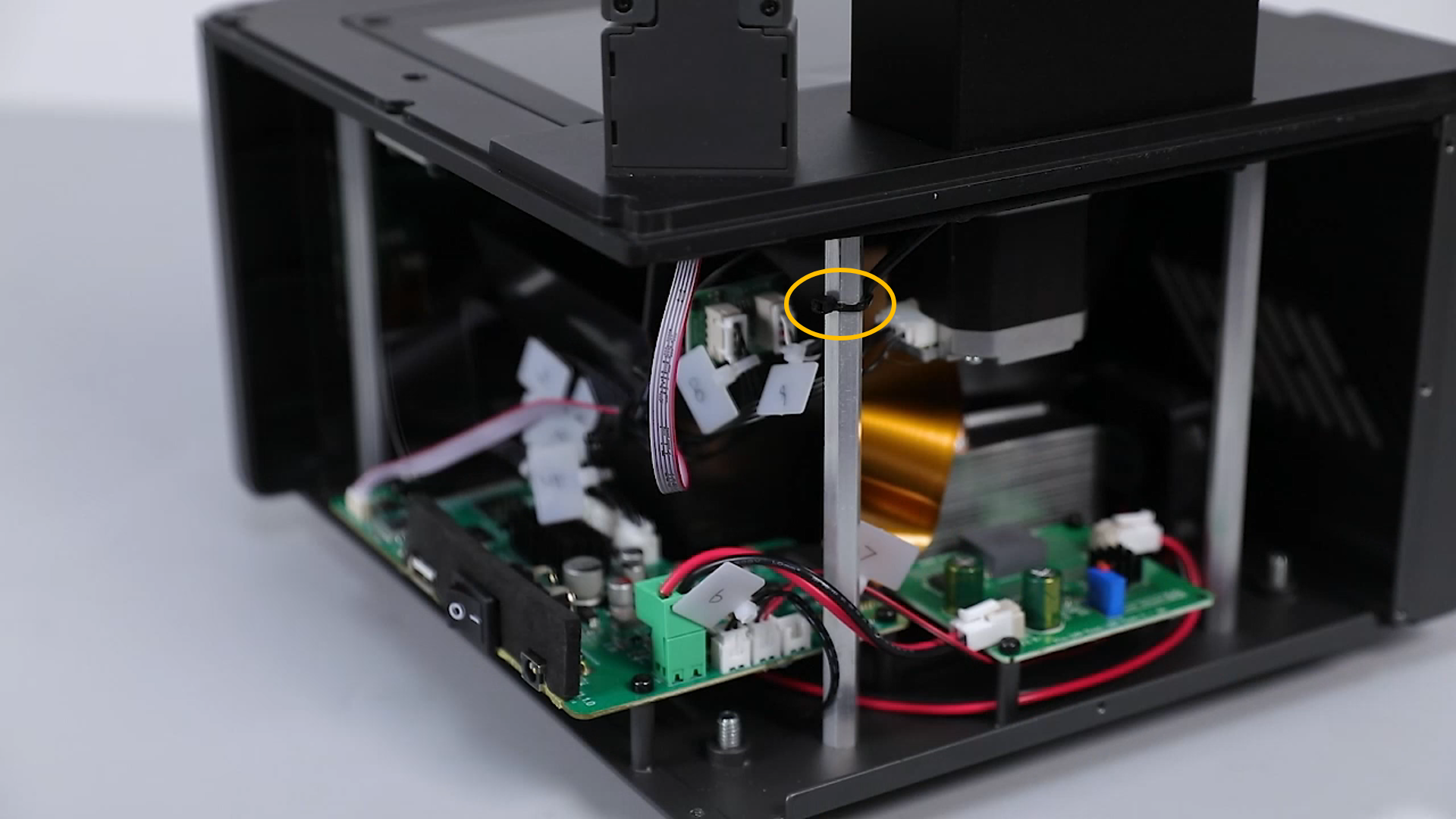
¶ Disconnect the Interface Board, UV Light, and Motherboard Cables
- Use diagonal cutting pliers to cut the zip tie securing the mechanical sensor ribbon cable.
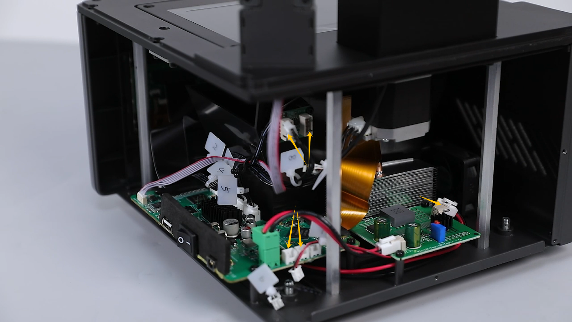
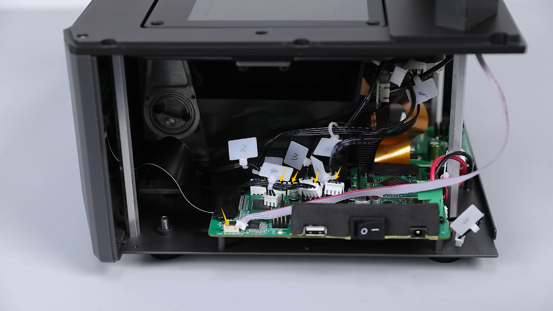
- Unplug the ribbon cables from the interface board, UV light, and motherboard ports.
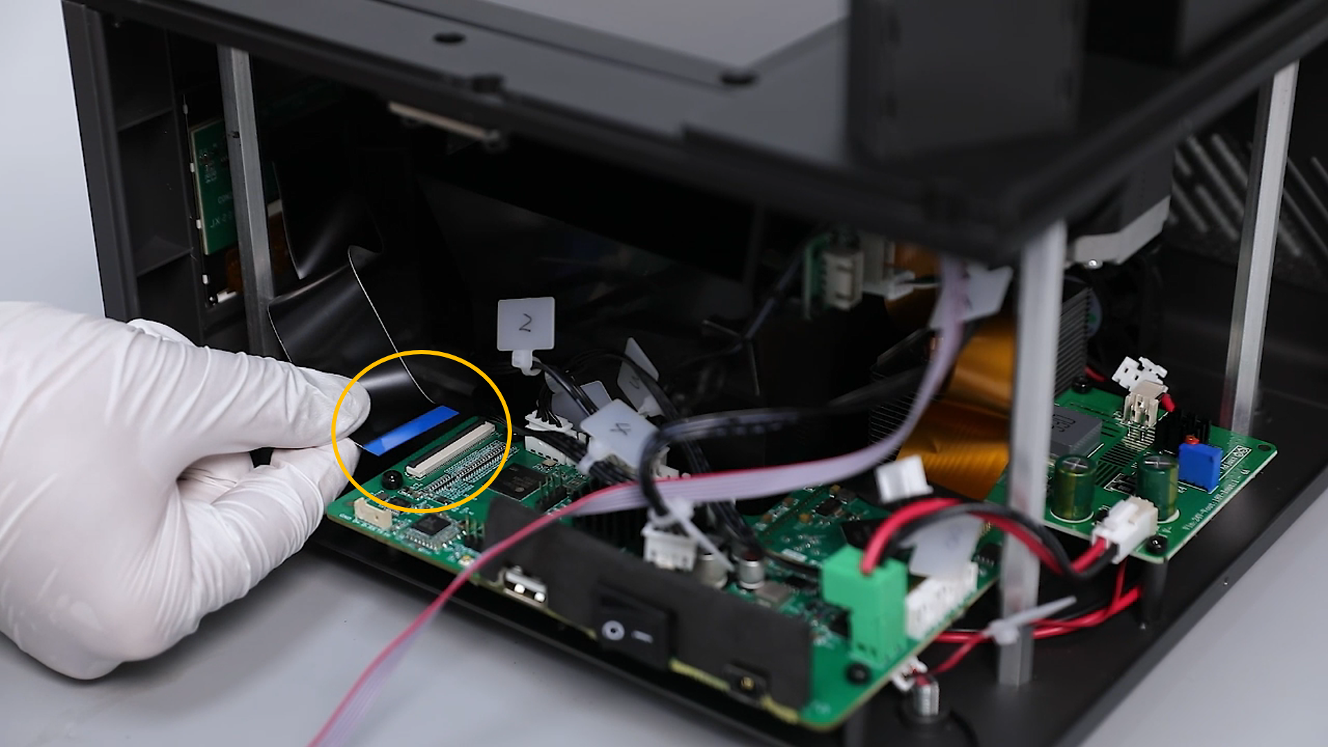
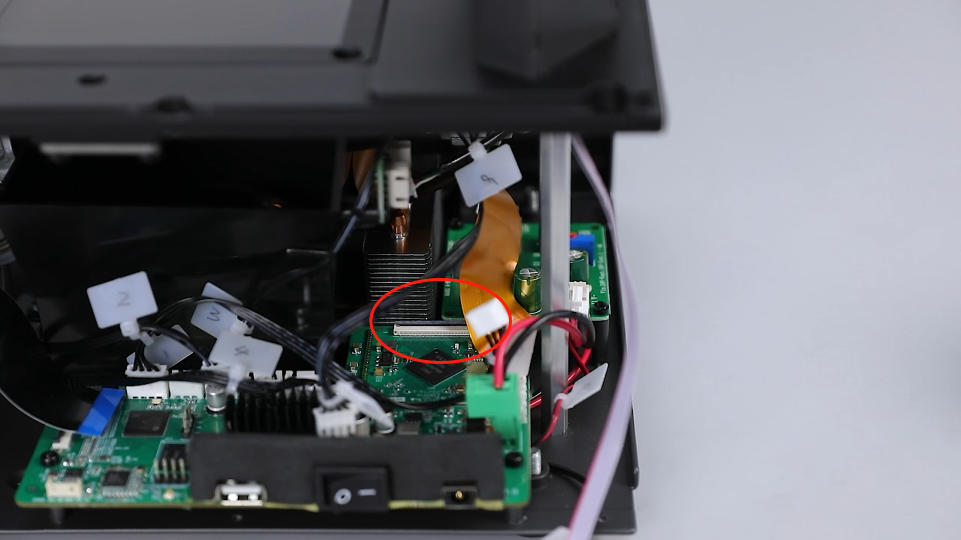
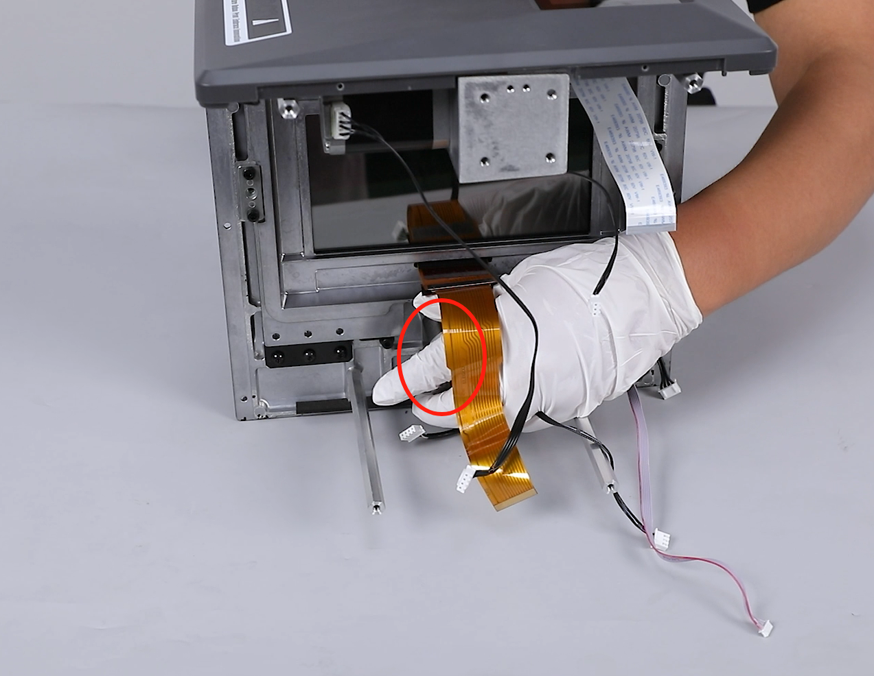
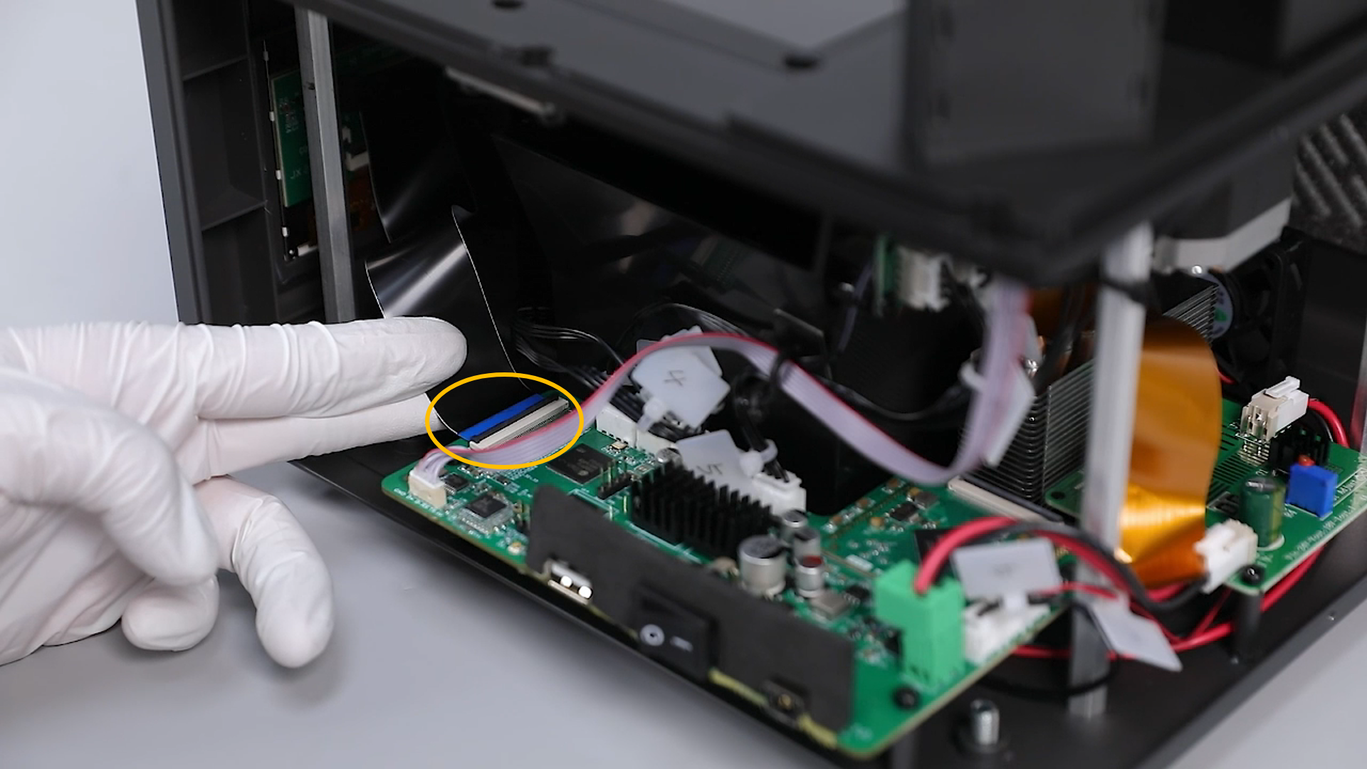
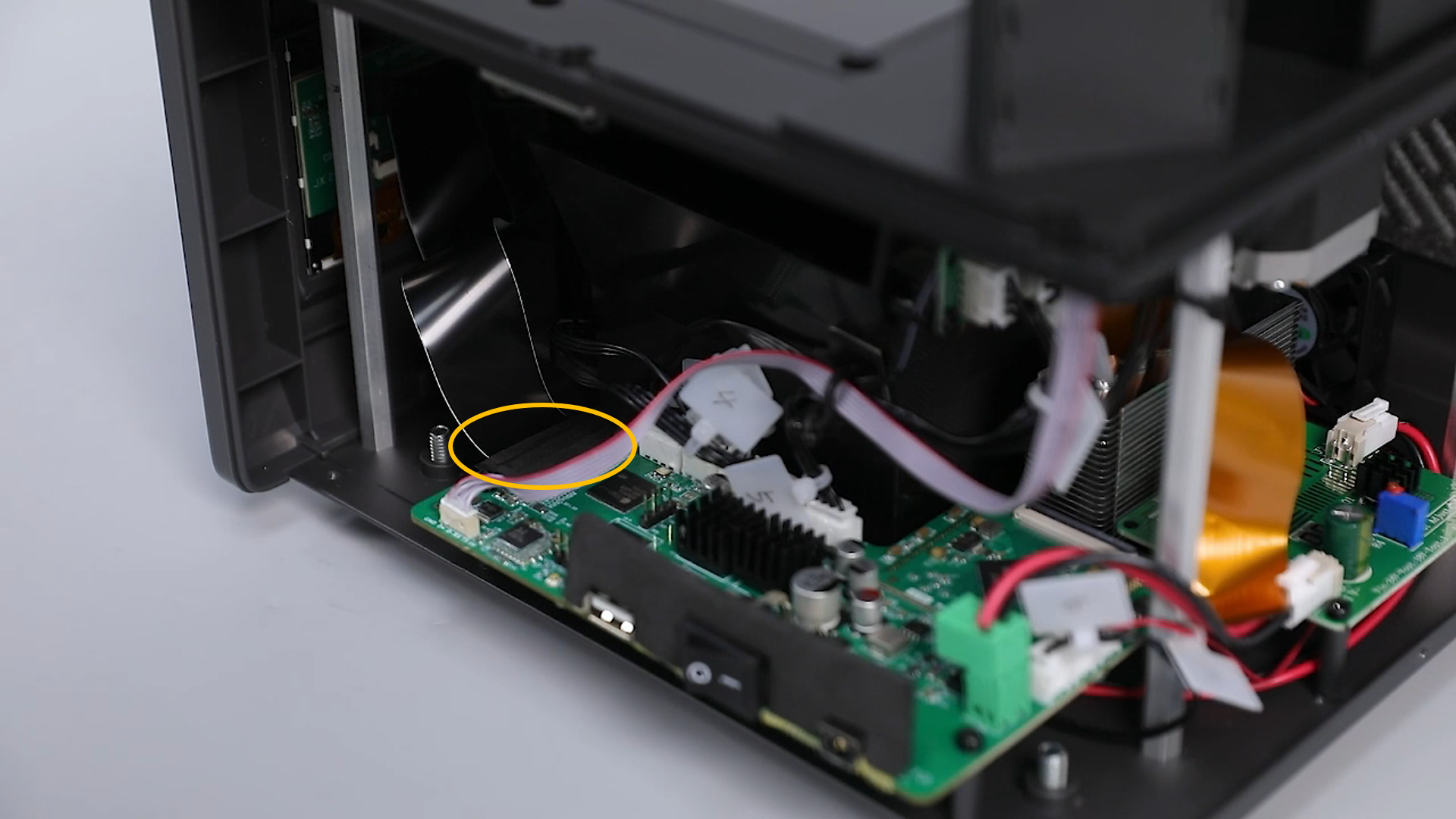
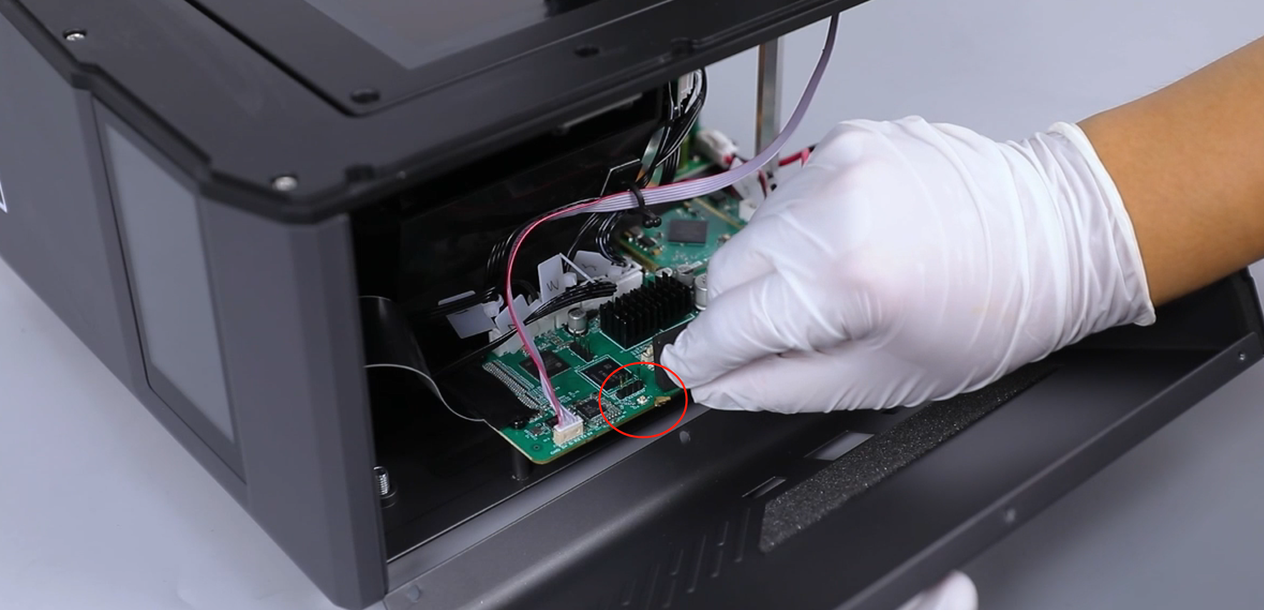
¶ Disconnect the Touch Screen and LCD Screen Ribbon Cables
- Peel off the black tape covering the touch screen port on the motherboard, lift the touch screen ribbon cable cover, and remove the touch screen ribbon cable.
(The black tape can be preserved for reuse.)
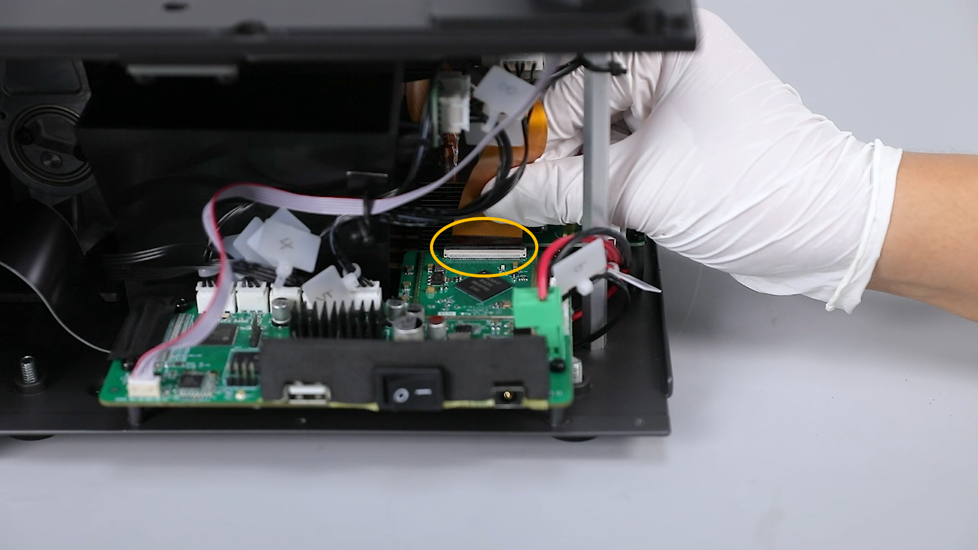
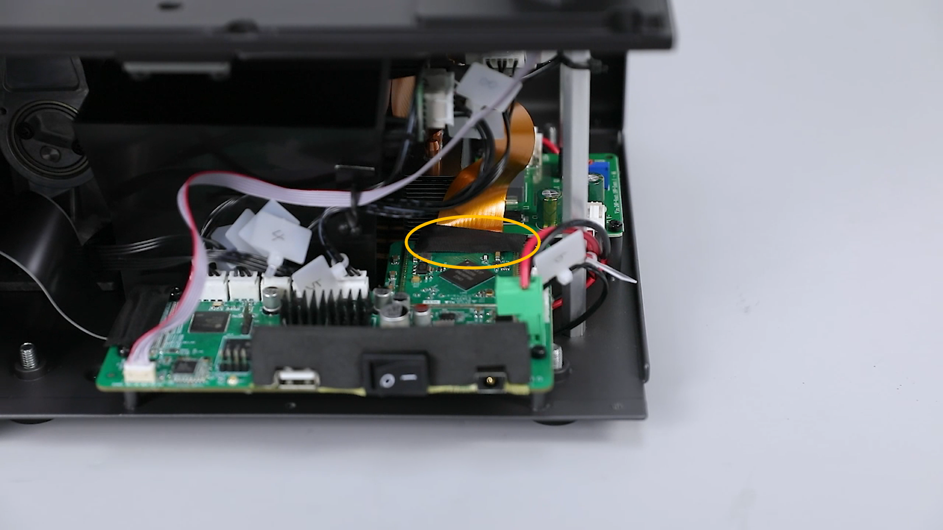
- Peel off the black tape covering the LCD screen port on the motherboard, lift the ribbon cable cover, and remove the LCD ribbon cable.
(The black tape can be preserved for reuse.)
¶ Remove the Left Cover and Base Cover
- Loosen 3 screws securing the top of the left cover using a 2.5 mm Allen wrench.

- Loosen 3 screws securing the bottom of the left cover using a 2.0 mm Allen wrench, and remove the left cover.
- Loosen two screws securing the bottom of the front cover using a 2.0 mm Allen wrench.

- Loosen eight screws securing the 3D printer base cover using a 2.5 mm Allen wrench, and remove the 3D printer base cover component.
Note: When loosening the last two screws, support the base cover to prevent it from falling.

¶ Remove the Z-Axis Top Plate and Lead Screw Nut
- Loosen 4 screws securing the Z-axis top plate using a 3.0 mm Allen wrench, and remove the Z-axis top plate.
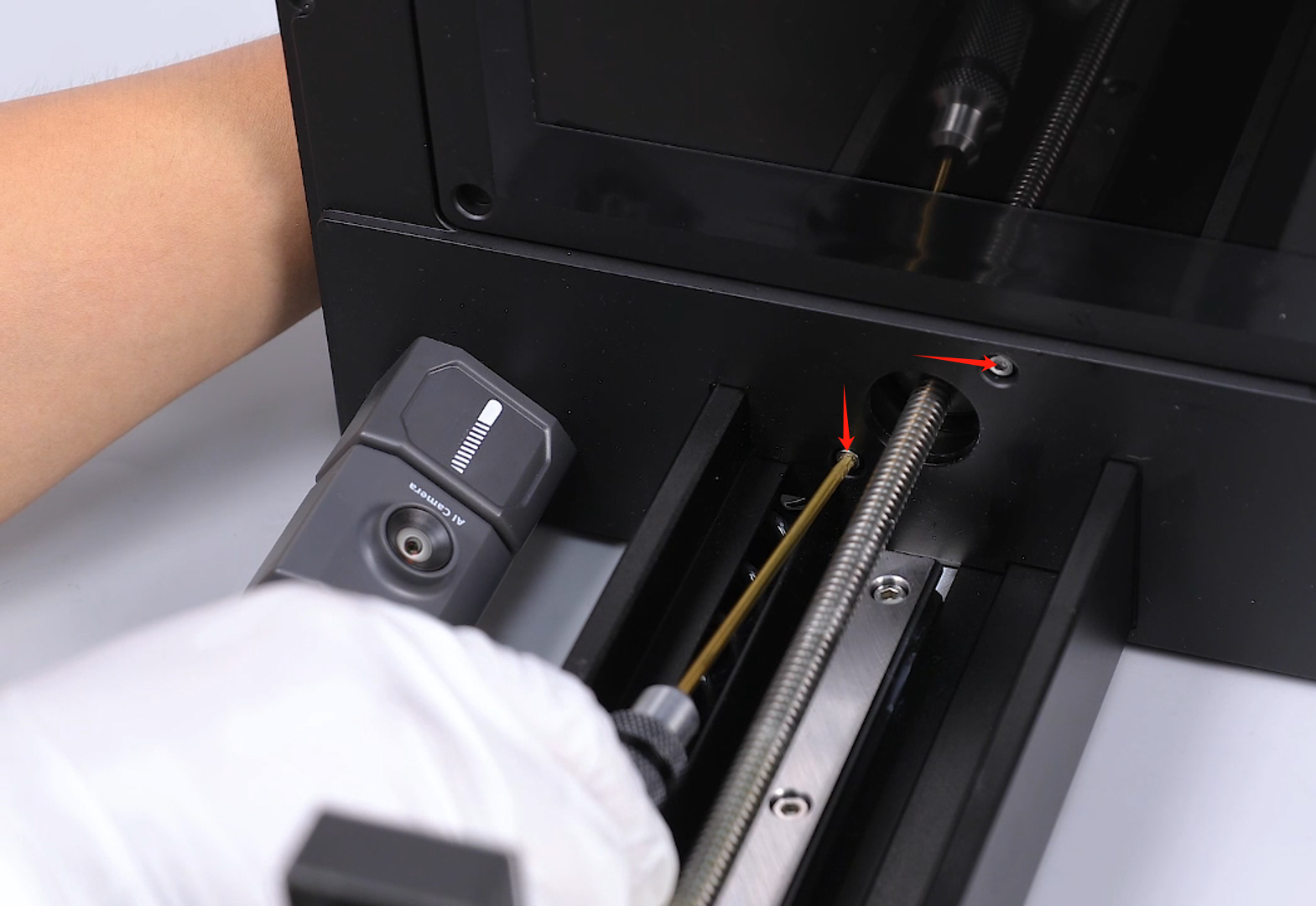
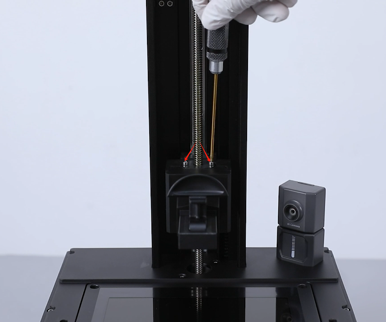
- Loosen two screws securing the lead screw nut using a 2.5 mm Allen wrench.
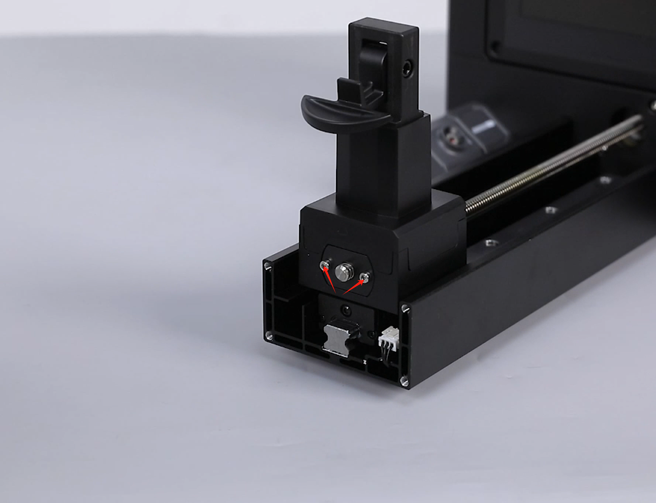
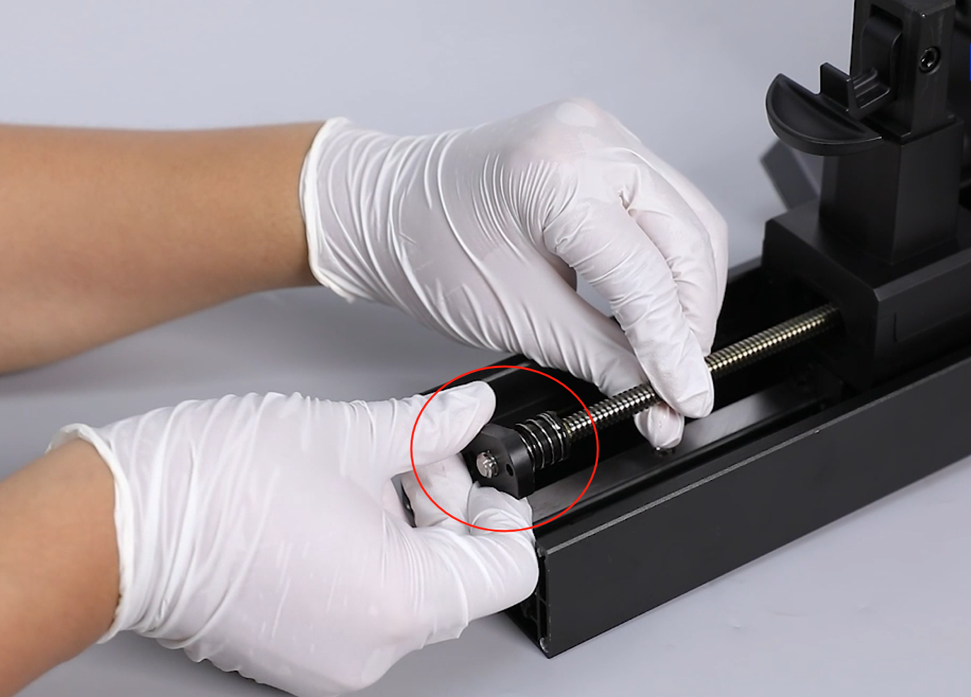
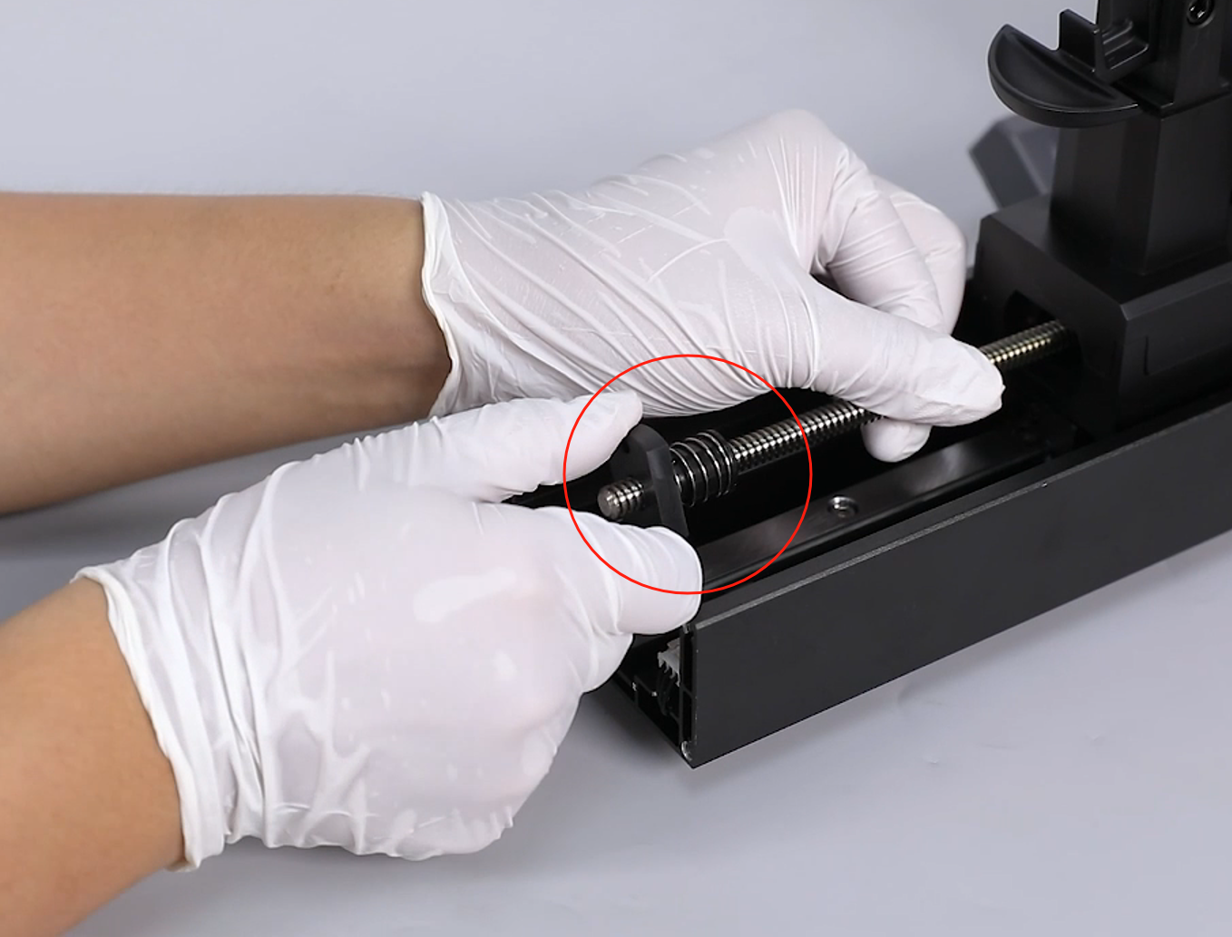
- Hold the lead screw with one hand and turn the lead screw nut with the other, removing the lead screw nut from the top of the lead screw.
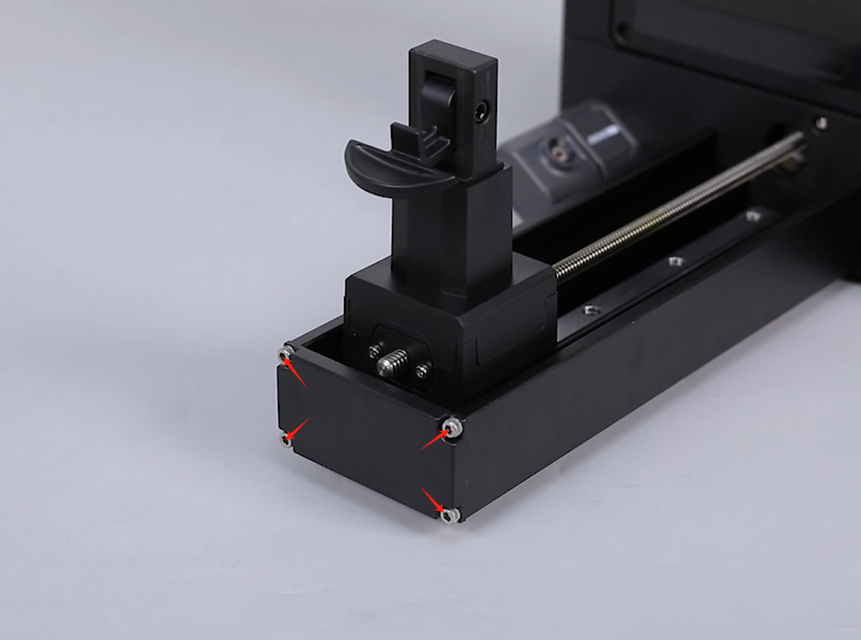
¶ Remove the Lead Screw Motor and Shock Absorber Pad
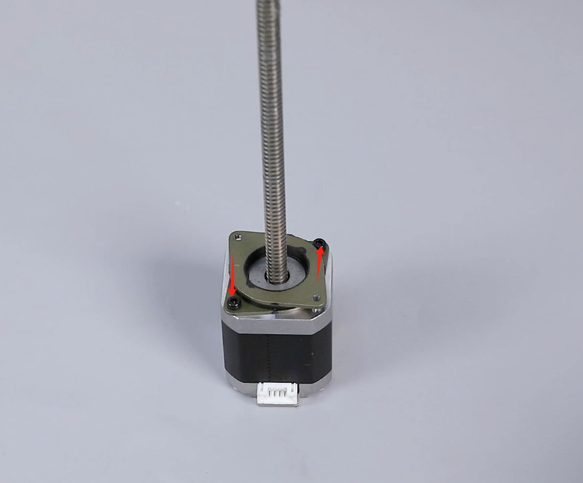
- Support the motor from behind and loosen two screws securing the motor using a 2.5 mm Allen wrench.

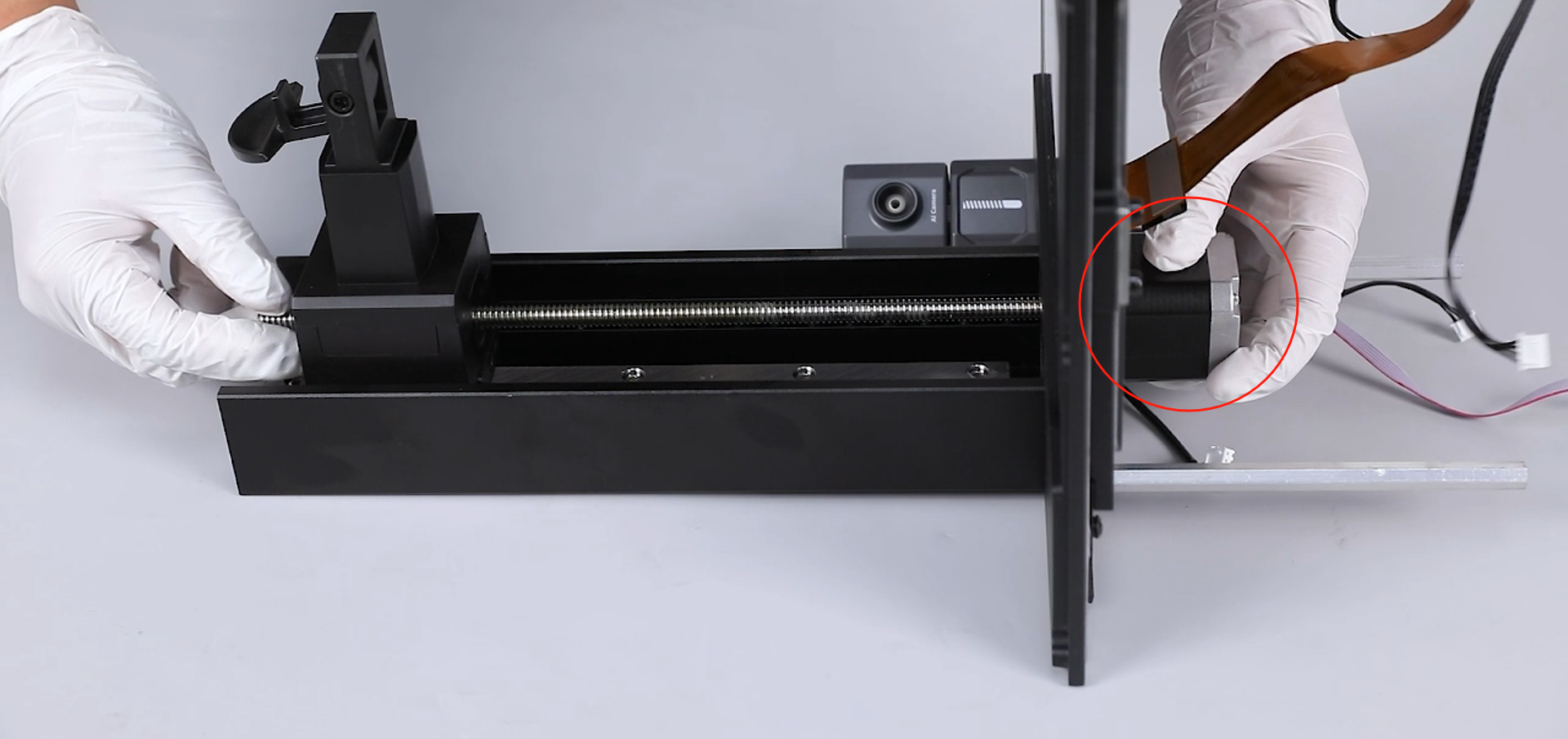
- Remove the motor assembly from the back.
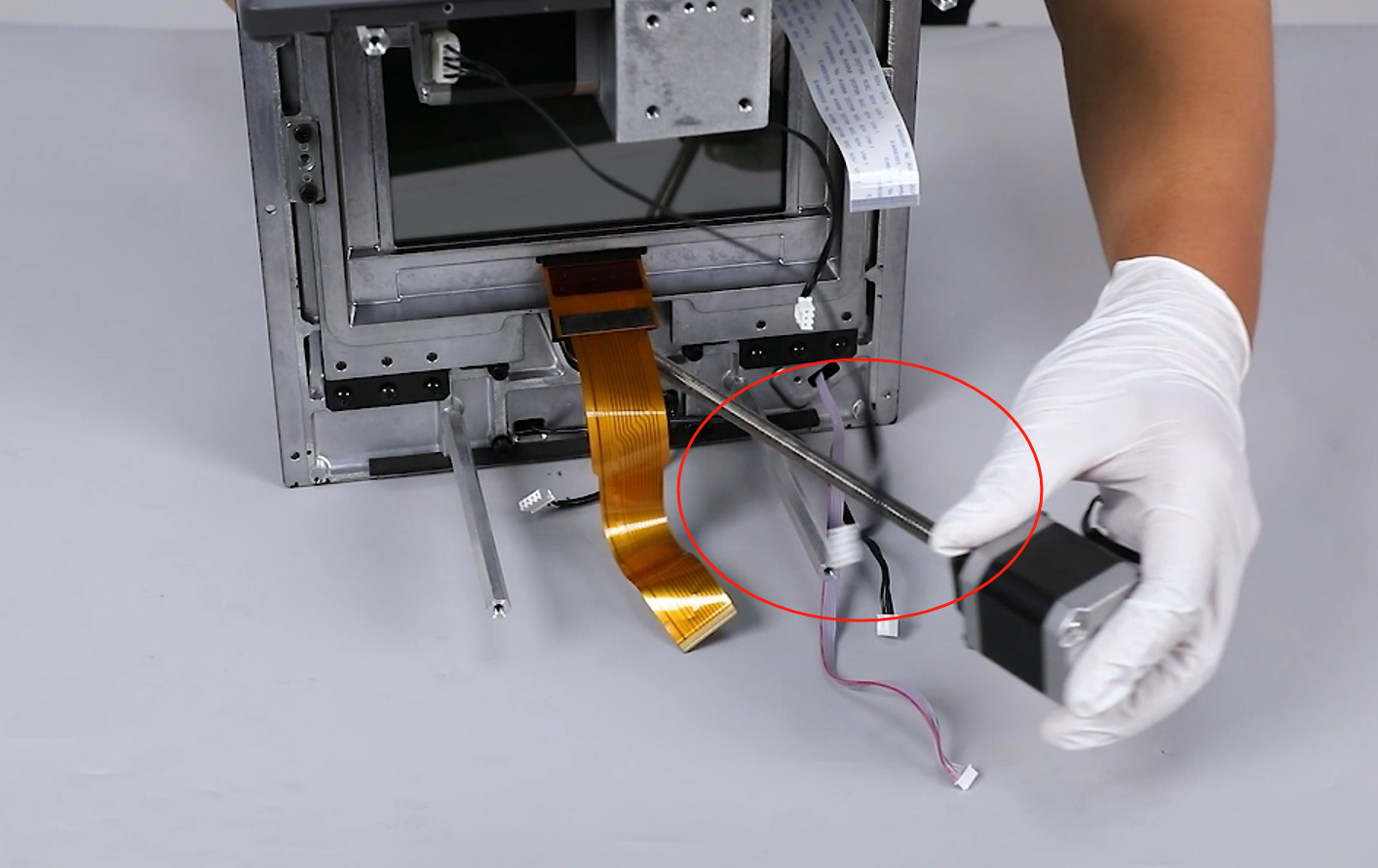
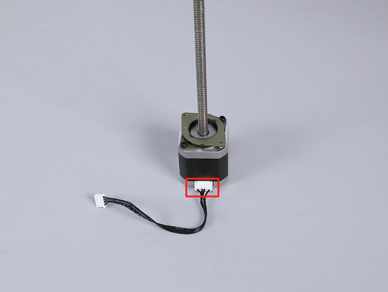
- Unplug the motor ribbon cable.
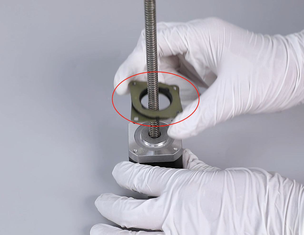
- Loosen two screws securing the shock absorber pad using a 2.5 mm Allen wrench, and remove the shock absorber pad upward.
¶ Install the New Lead Screw Motor
- Retrieve the new motor, align it with the screw holes, place the shock absorber pad in the mounting position, and tighten two securing screws using a 2.5 mm Allen wrench.

- Insert the motor ribbon cable.

- Align the motor assembly with the screw holes and place it in the mounting position.
- Using a 2.5 mm Allen wrench, first screw in "three-quarters" of the two screws securing the motor, then gradually tighten the two screws synchronously.
¶ Reinstall the Lead Screw Nut and Z-Axis Top Plate
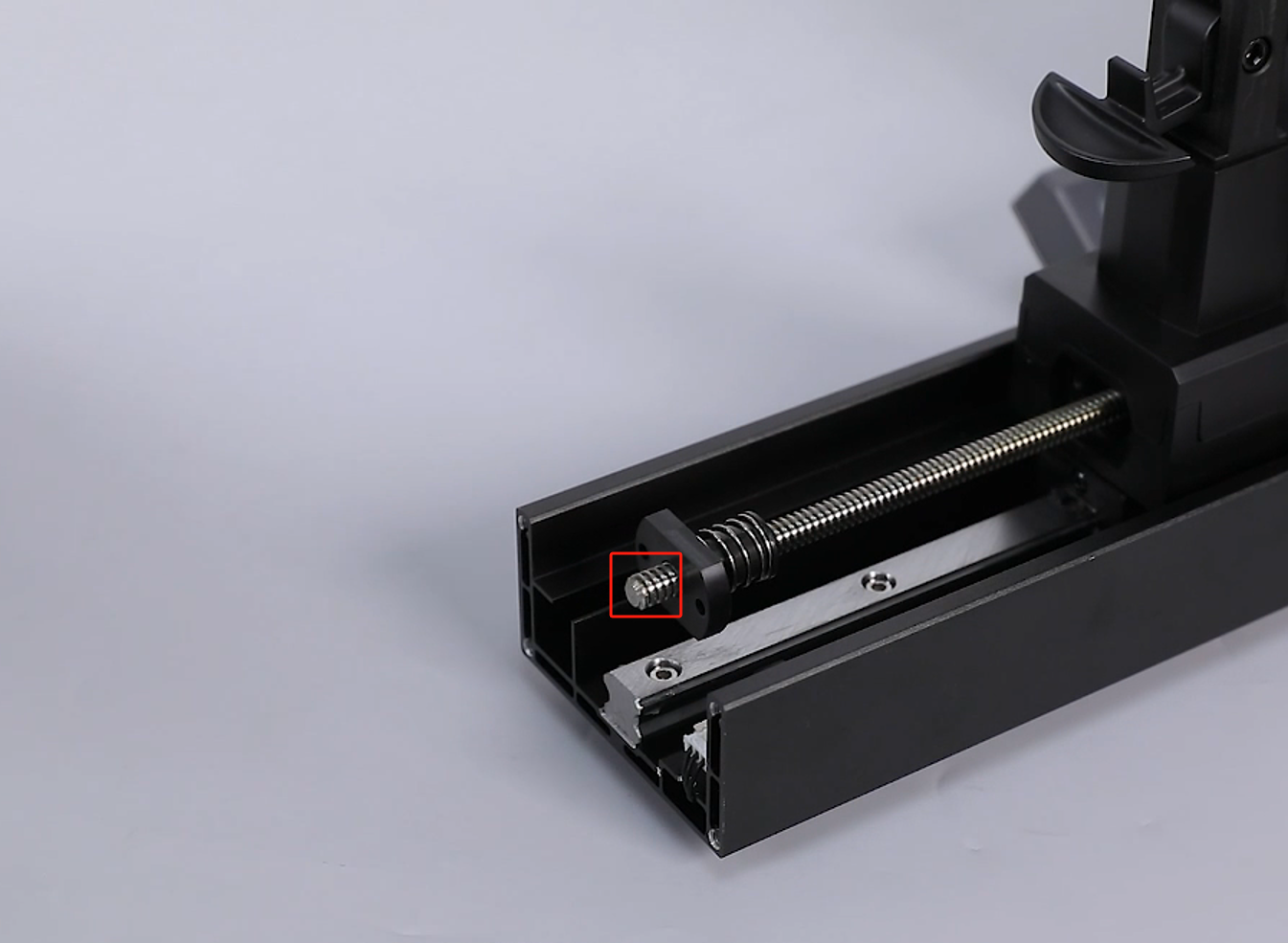
- Retrieve the lead screw nut, hold the lead screw with one hand, and turn the lead screw nut with the other, installing the lead screw nut onto the top of the lead screw.
- Screw it approximately 1 cm from the top of the lead screw.
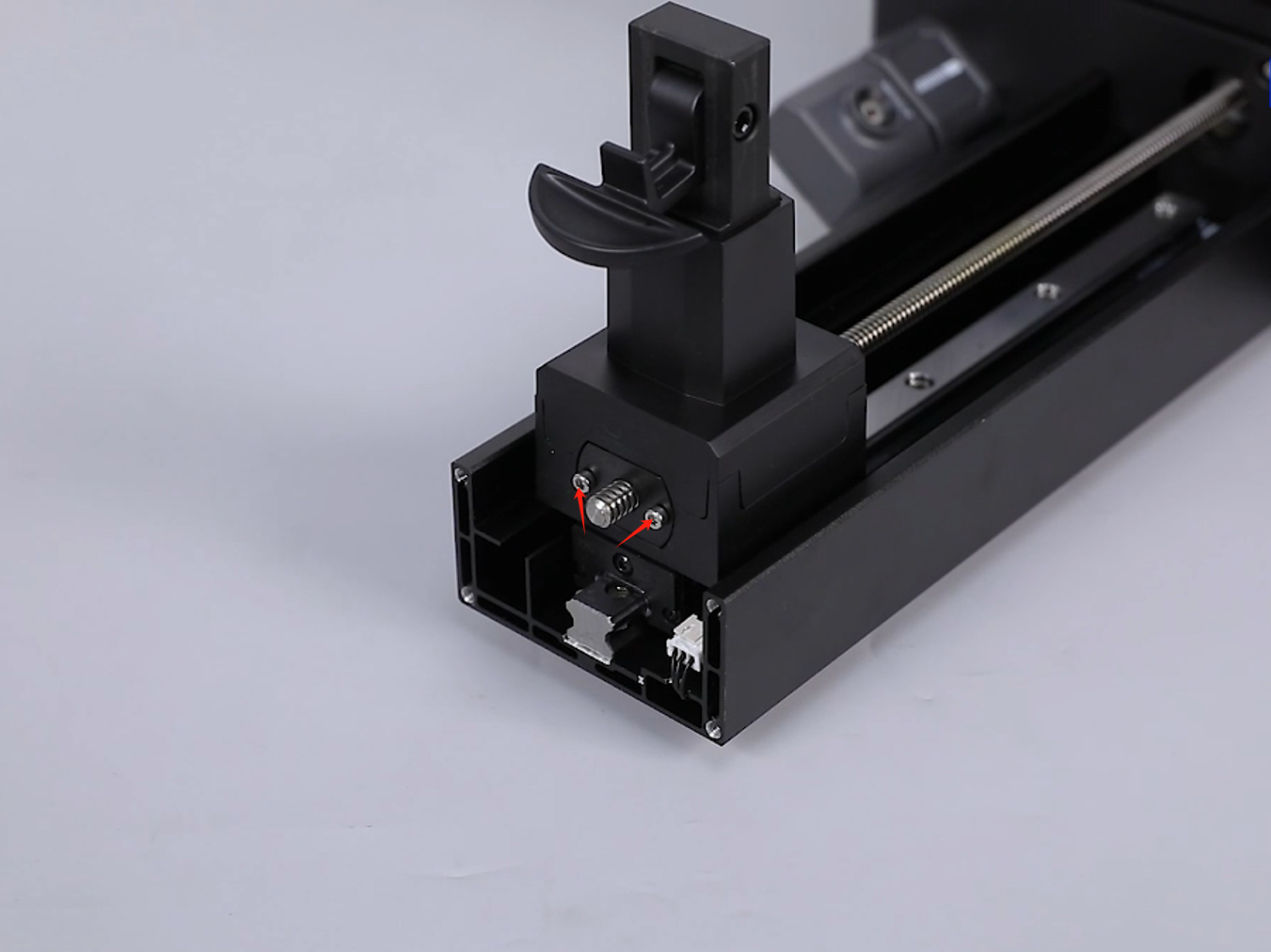
- Push the connecting arm to align the screw holes with the lead screw nut, and using a 2.5 mm Allen wrench, screw in "three-quarters" of the two securing screws.
Note: These two screws should not be tightened yet; they will be tightened later.
- Retrieve the top plate, align it with the screw holes, place it in the mounting position, and tighten four securing screws using a 3.0 mm Allen wrench.

¶ Reinstall the Base Cover and Left Cover
- Retrieve the base cover component, distinguish the base cover installation direction based on the screw hole positions on the base cover.
- Align the base cover with the screw holes, place it in the mounting position, and tighten eight securing screws using a 2.5 mm Allen wrench. Note: Manage all the ribbon cables to avoid pinching them during installation.
- Tighten two screws securing the bottom of the front cover using a 2.0 mm Allen wrench.
- Retrieve the left cover, align it with the screw holes, place it in the mounting position, and tighten 3 securing screws using a 2.5 mm Allen wrench.
- Tighten 3 screws securing the bottom of the left cover using a 2.0 mm Allen wrench.

¶ Reconnect and Organize the Internal Ribbon Cables
- Based on the labels, plug each ribbon cable back into the motherboard and interface board.

- Use zip ties to secure the mechanical sensor ribbon cable and organize all the ribbon cables, placing them in the cable clips.
¶ Reconnect the Touch Screen and LCD Screen Ribbon Cables
- Insert the touch screen ribbon cable, secure the ribbon cable cover, and apply tape.
Note: The touch screen ribbon cable has a specific installation direction.
- Insert the LCD screen ribbon cable, secure the ribbon cable cover, and apply tape.
Note: The LCD screen ribbon cable has a specific installation direction.
¶ Reinstall the Right Cover and Rear Cover
- Retrieve the right cover, and plug the wifi ribbon cable back into the motherboard port.
- Align the right cover with the screw holes and button holes, place it in the mounting position, and tighten 3 securing screws using a 2.5 mm Allen wrench.
- Tighten 3 screws securing the bottom of the right cover using a 2.0 mm Allen wrench.

- Retrieve the 3D printer rear cover, and tighten 7 securing screws using a 2.0 mm Allen wrench.
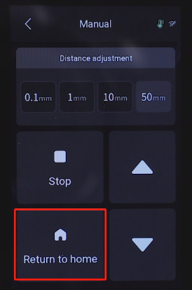
¶ Lower the Z-Axis and Tighten the Lead Screw Nut
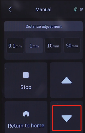
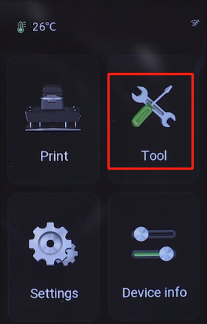
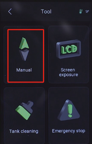
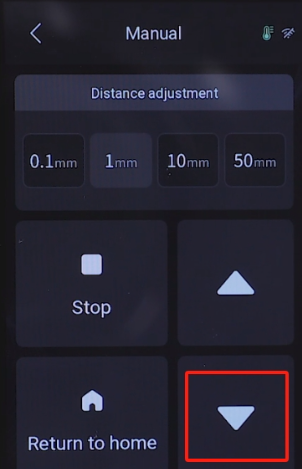
- Turn on the 3D printer power. On the touchscreen, select "Tools-Manual-50 mm" and click to lower the Z-axis.

- After the Z-axis descends to the bottom, using a 2.5 mm Allen wrench, gradually tighten the two screws securing the lead screw nut.
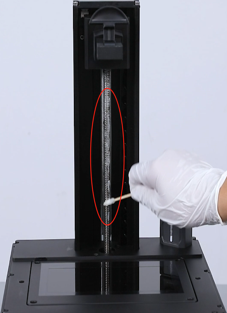
¶ Lubricate the Lead Screw and Test the Z-Axis
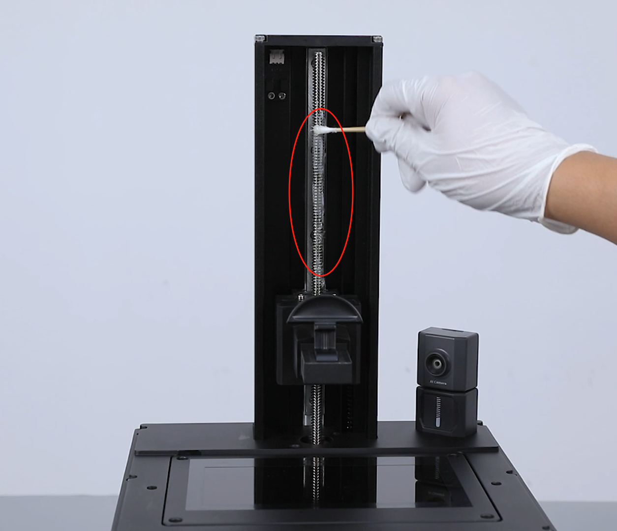
- Apply lubricant to the upper and lower parts of the lead screw and use a cotton swab to spread the lubricant evenly.
- Select "Home" to perform a homing operation on the touchscreen,, and the 3D printer will move upward to the home position.
- Click the down button again to observe normal Z-axis movement, and the 3D printer is now ready for normal use.