¶ Tools and Materials
- A 2.0mm Allen key x 1
- A 2.5mm Allen key x 1
- A new X-axis limit switch

¶ Tutorial Video
¶ Instruction
- Power off the printer and unplug the power cord.
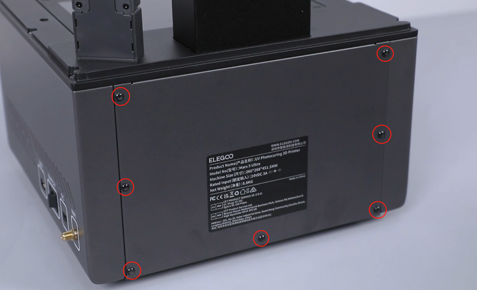
- Use a 2.0 mm Allen key to loosen the 7 screws securing the back cover of the printer and remove the back cover.

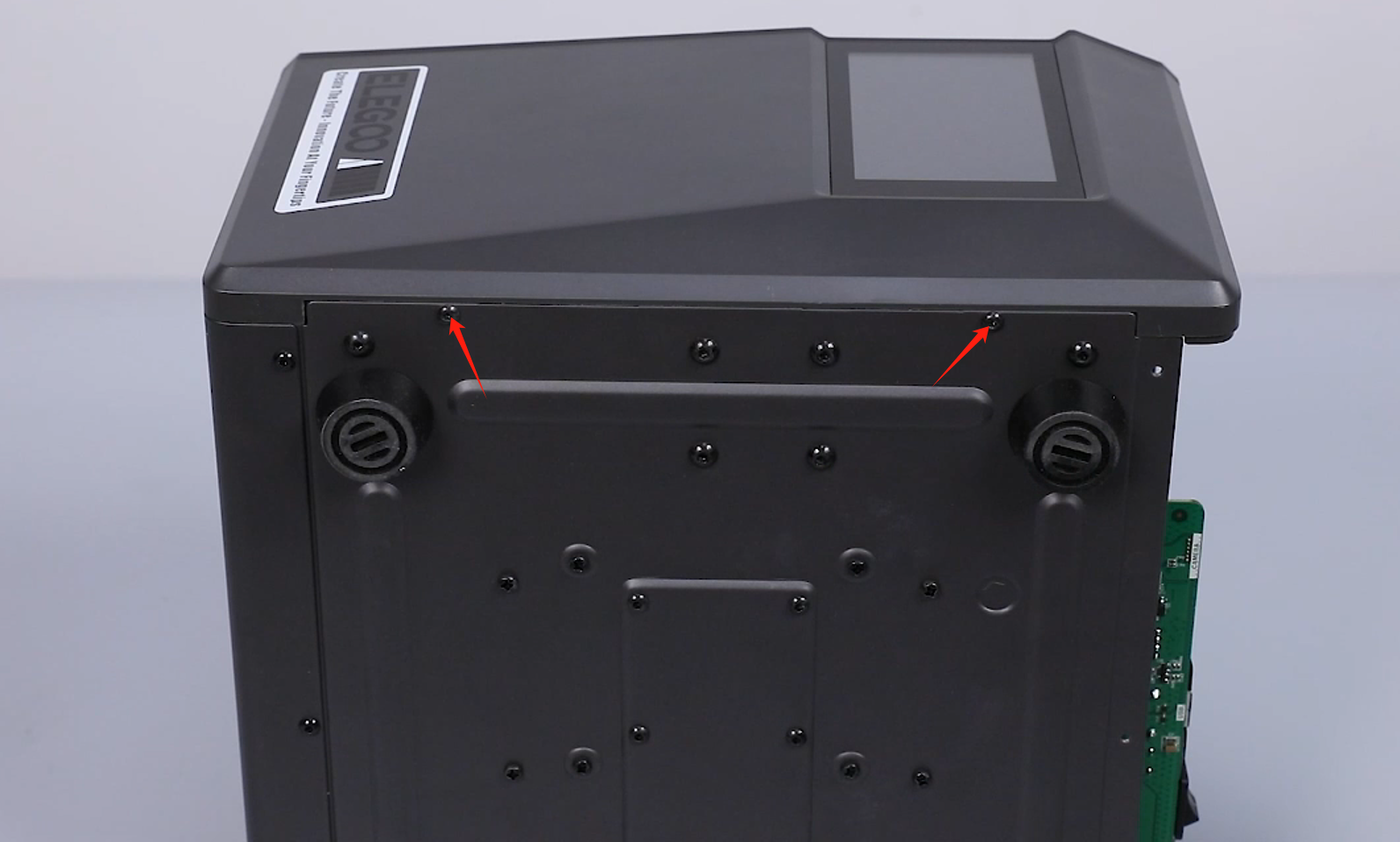
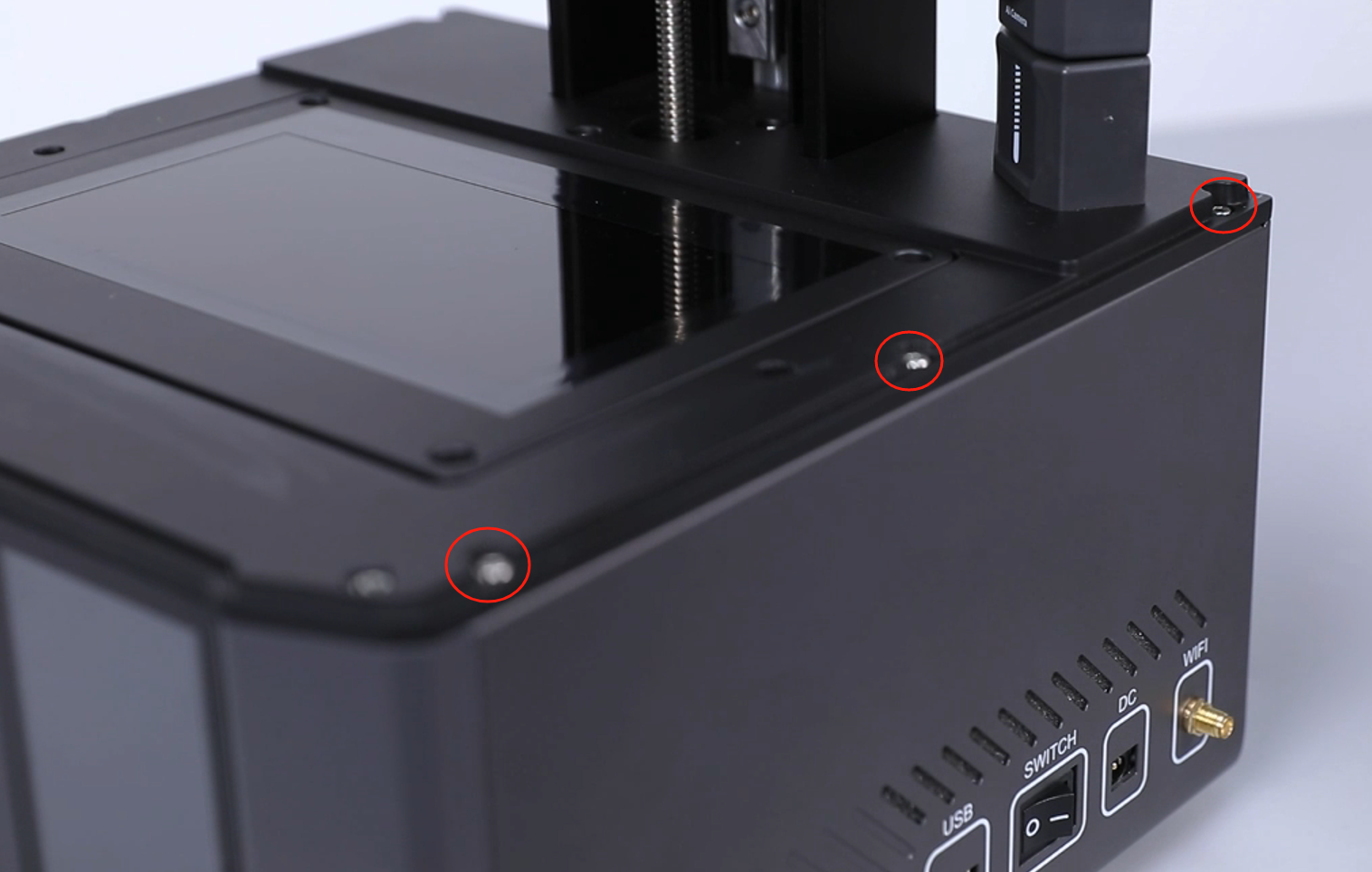
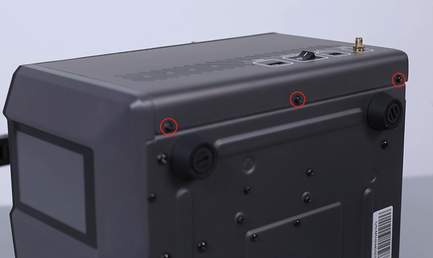
- Loosen the 3 screws fixed at the upper part of the right cover using a 2.5 mm Allen key.

- Loosen the 3 screws fixed at the lower part of the right cover using a 2.0 mm Allen key.

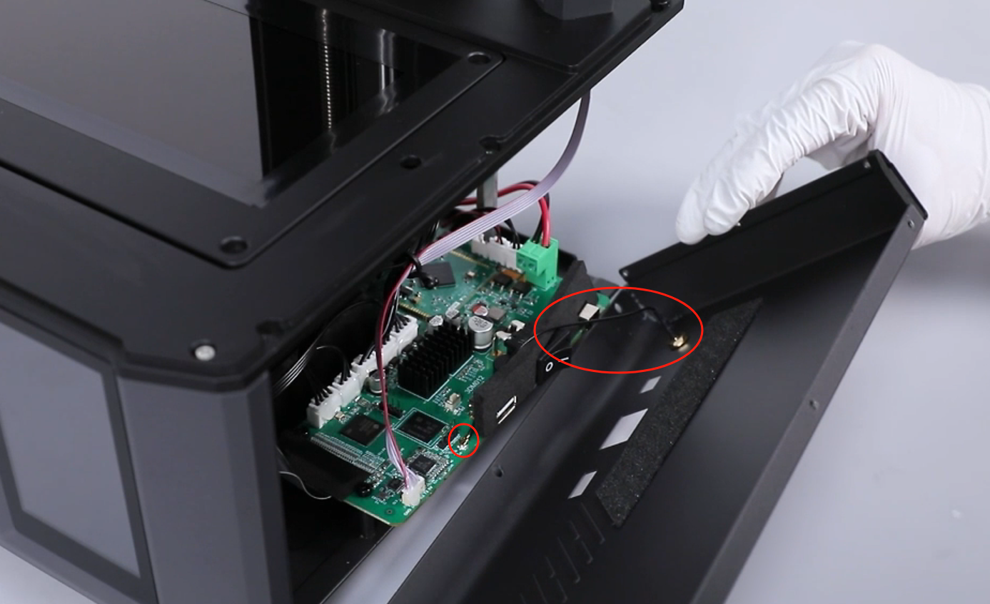
- Open the right cover slowly as there is a WiFi cable inside. Unplug the WiFi cable connector from the motherboard. Remove the right cover.
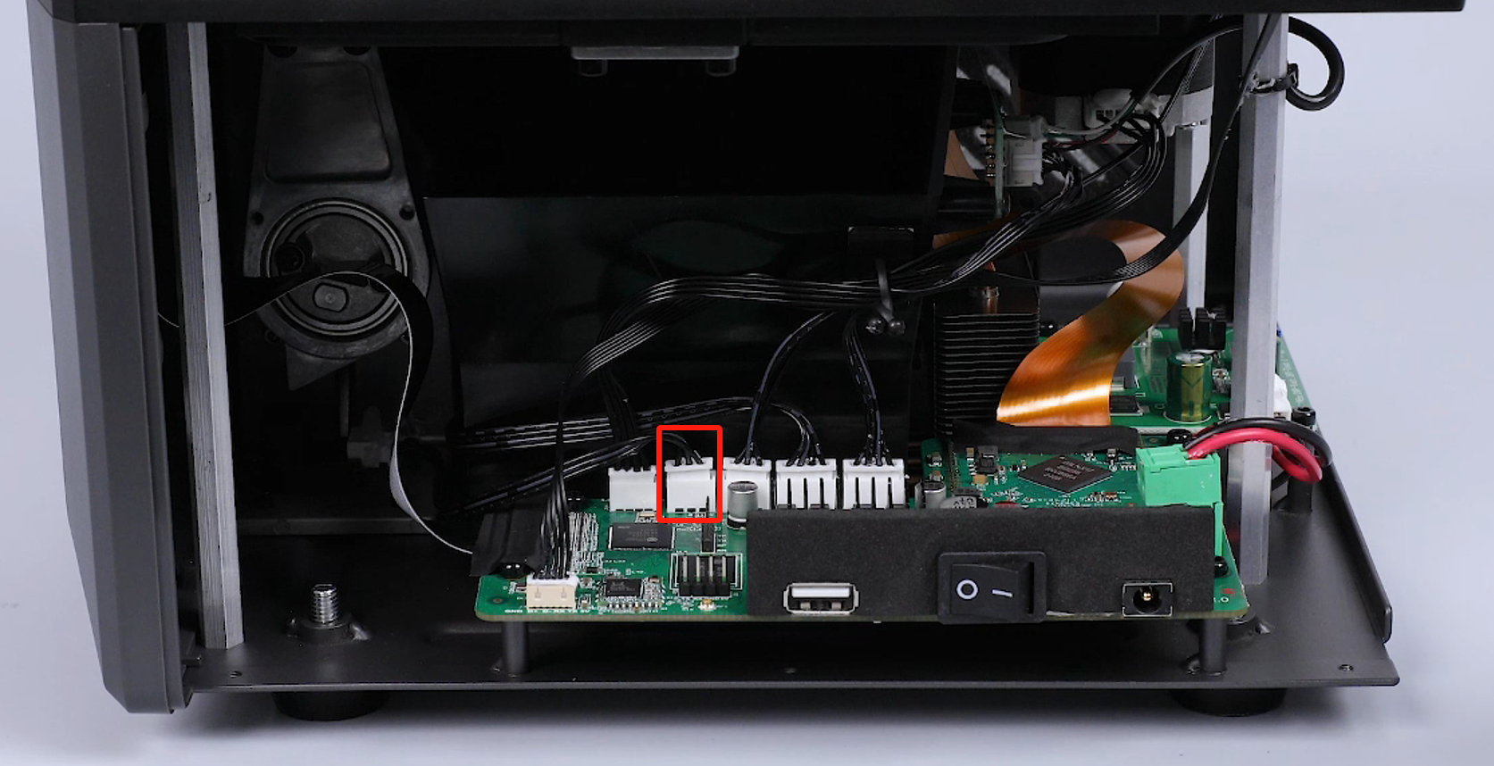
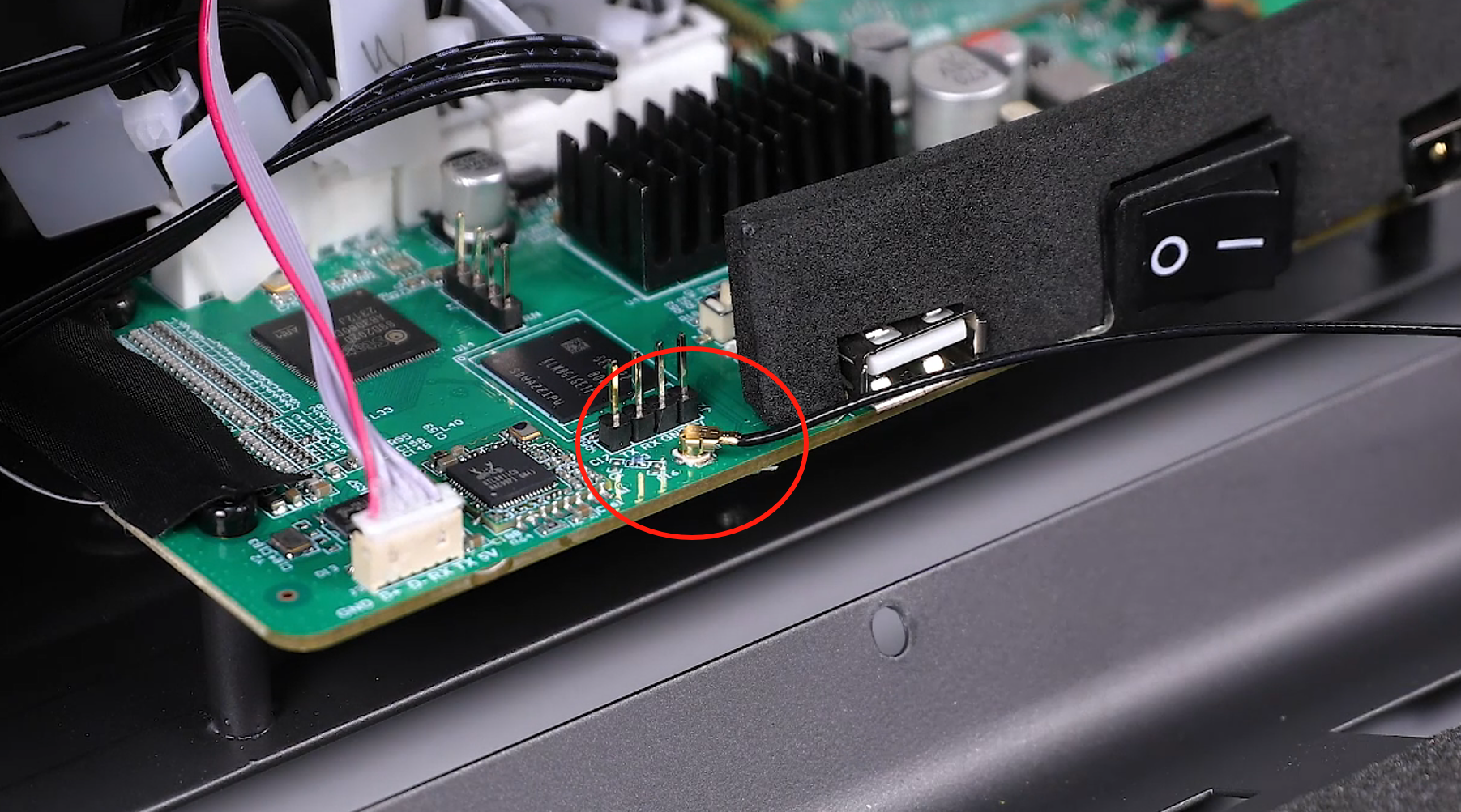
- Unplug the cable of the X-axis limit switch port on the motherboard.

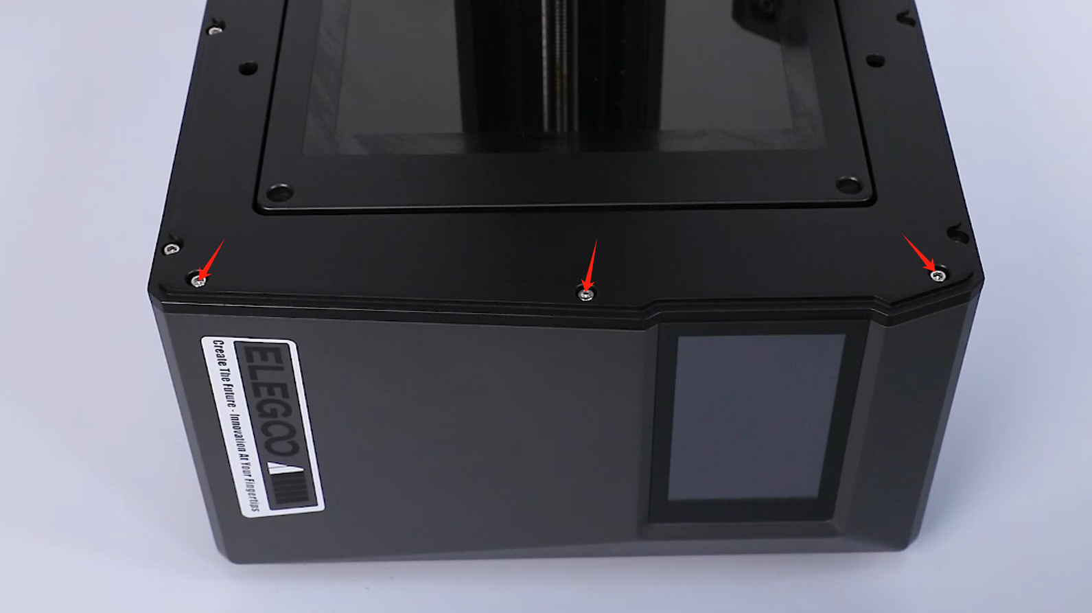
- Use a 2.5 mm Allen wrench to loosen the 3 screws fixed at the upper part of the front cover.

- Use a 2.0 mm Allen key to loosen the 2 screws underneath the front cover.
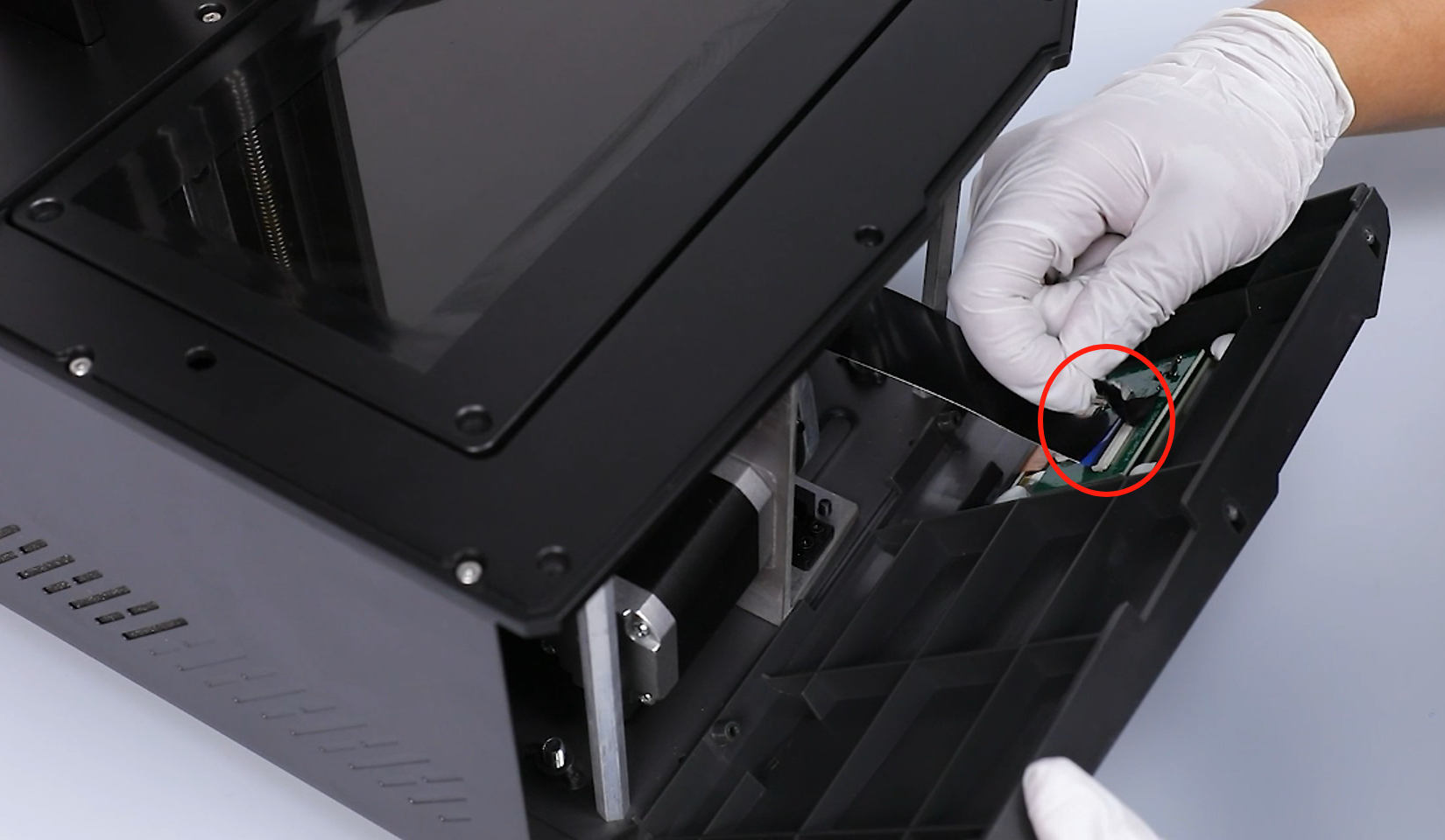
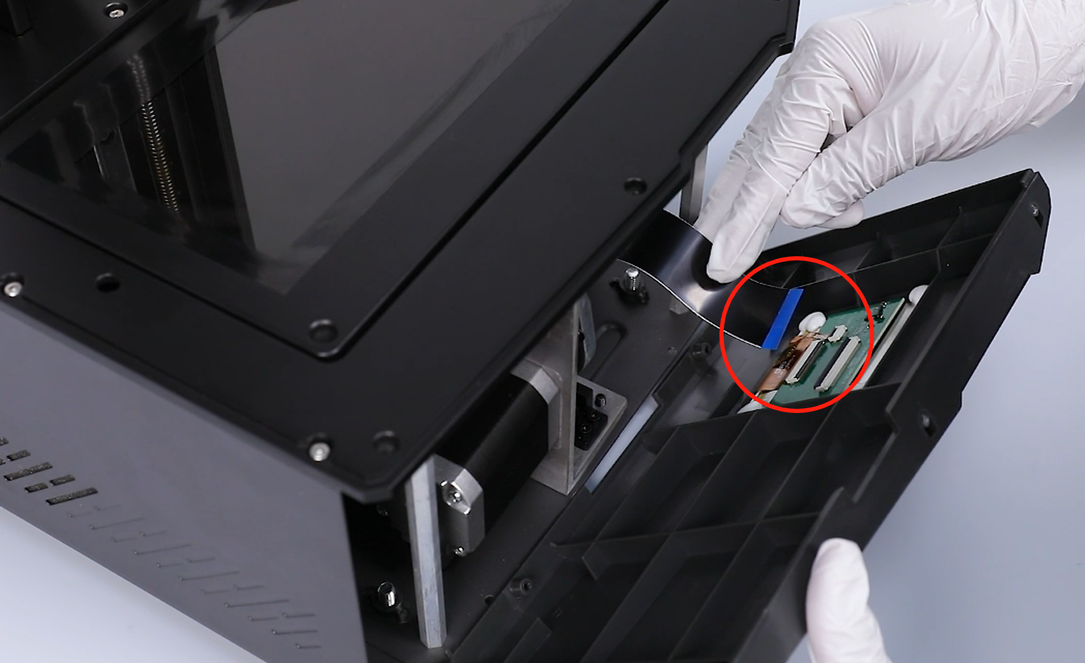
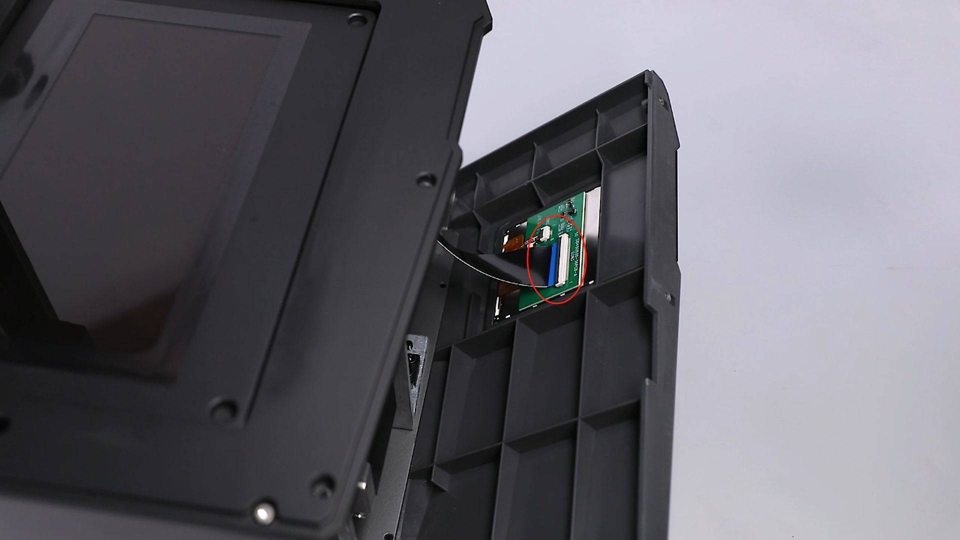
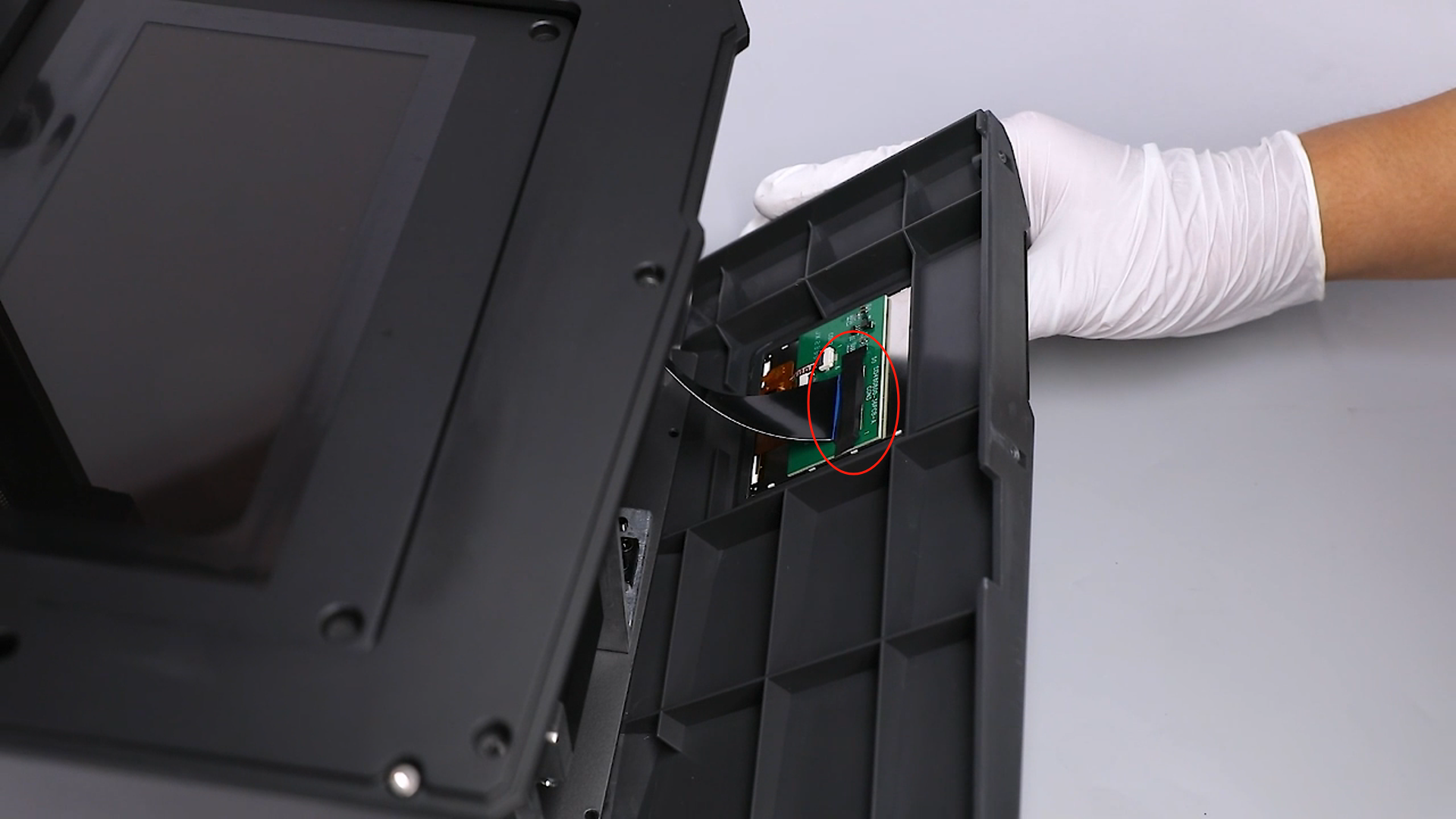
- Open a gap of the front cover and peel off the black tape adhered to the touchscreen port. Lift the pressing cover of the ribbon cables and remove the ribbon cables of the touchscreen.
Note: There are ribbon cables inside. Take care to remove the cover.
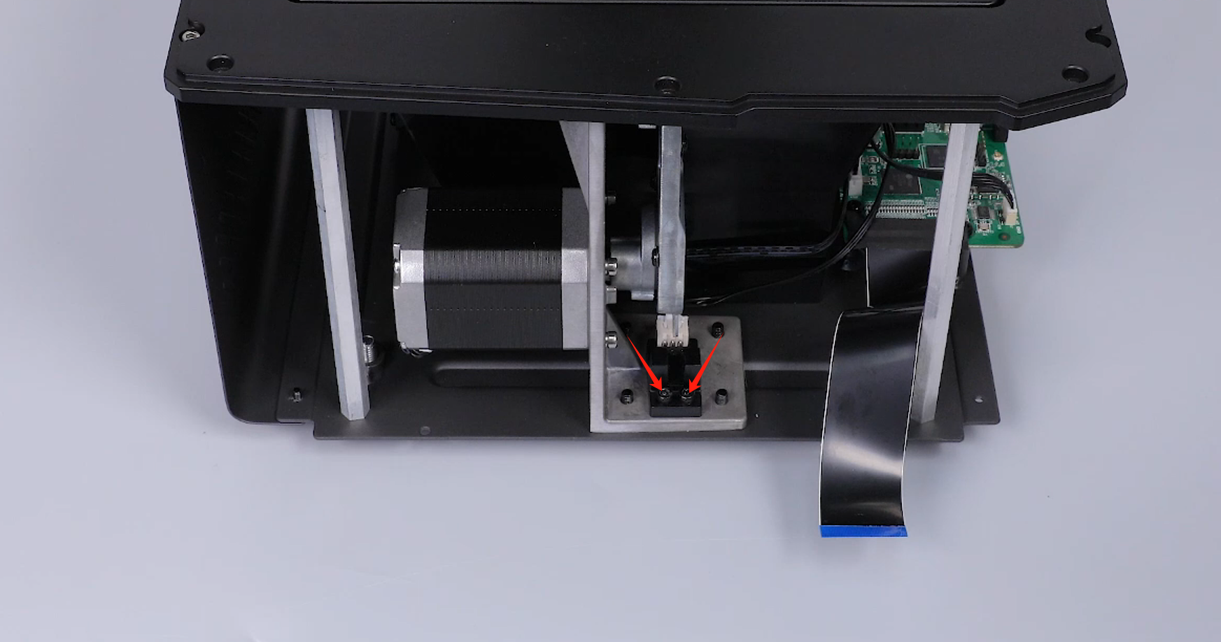
- Loosen the 2 screws securing the X-axis limit switch using a 2.5 mm Allen wrench.
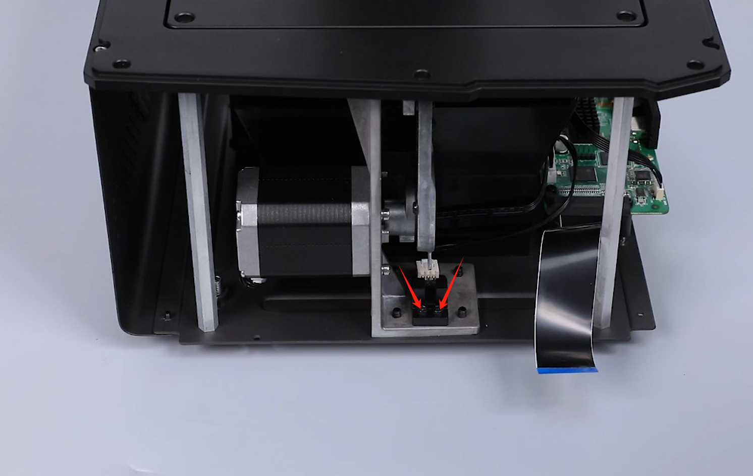
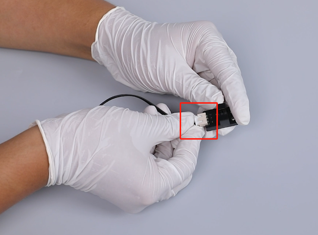
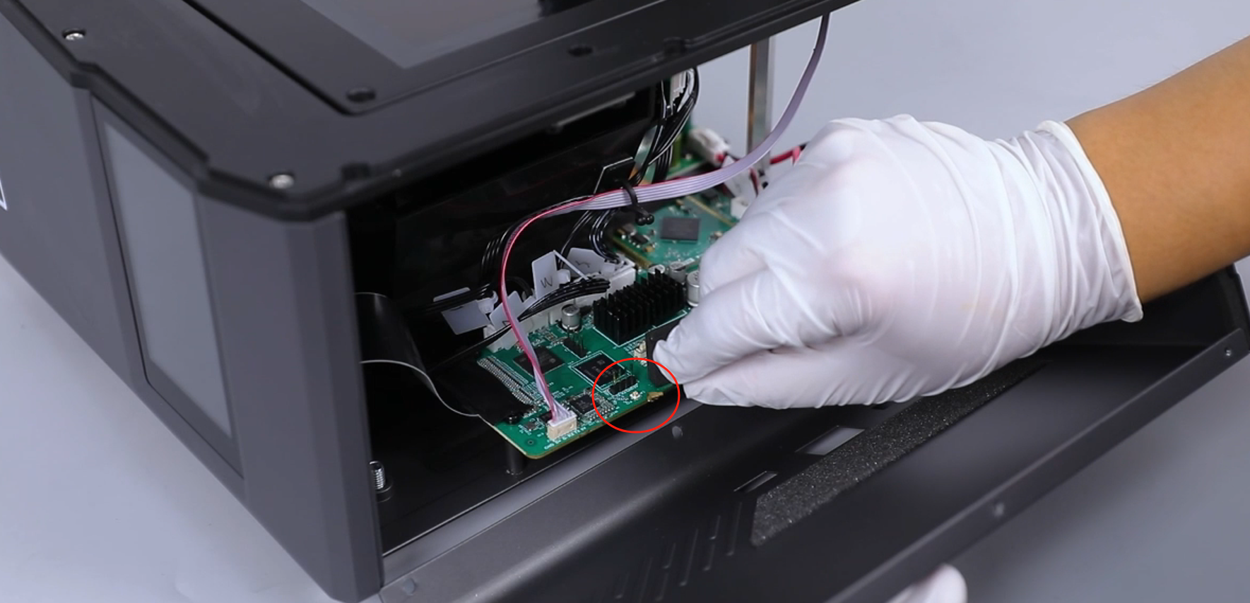
- Organize the cable. Remove the X-axis limit switch assembly. Unplug the cable of the X-axis limit switch port.
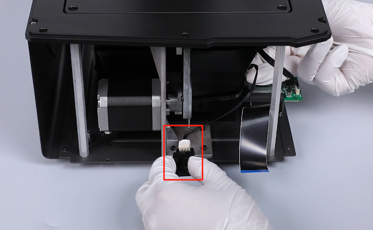
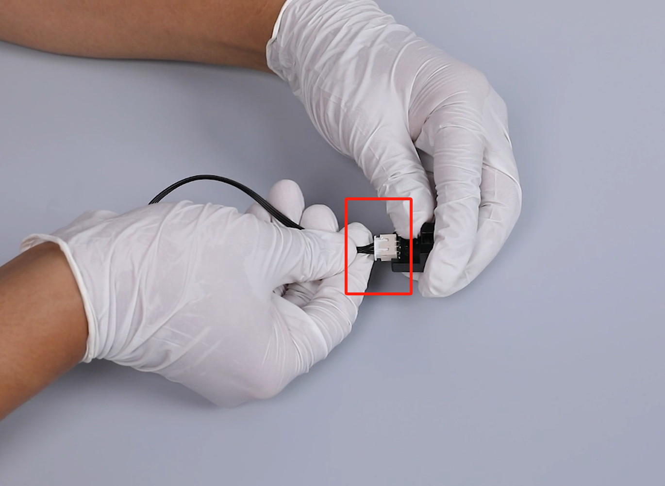
- Prepare the new X-axis limit switch. Insert the ribbon cables of the Z-axis limit switch port.
- Put the new X-axis limit switch in the installation position. Tighten the two screws securing the limit switch using a 2.5mm Allen key.
- Place the front cover in the installation area in the front of the printer. Insert the touchscreen cable into the touchscreen port.
Note: The touchscreen ribbon cables have a fixed installation position.
- Stick the black tape to the port of the touchscreen ribbon cables.
- Put the front cover in the installation position by aligning it with the screw holes. Use a 2.5 mm Allen wrench to tighten the 3 screws securing the upper part of the front cover.
- Use a 2.0 mm Allen key to tighten the 2 screws underneath the front cover.

- Insert the ribbon cables of the X-axis limit switch into the port on the motherboard.
- Prepare the right-side cover. Insert the Wi-Fi cable into its port on the motherboard.
- Align the right-side cover with the screw holes and button holes and put tit in the installation position. Tighten the three screws securing the right-side cover using a 2.5mm Allen key.
- Tighten the three screws fixed at the lower part of the right-side cover using a 2.0mm Allen key.
- Prepare the back cover of the printer. Use a 2.0 mm Allen wrench to tighten the 7 screws securing the back cover of the printer.
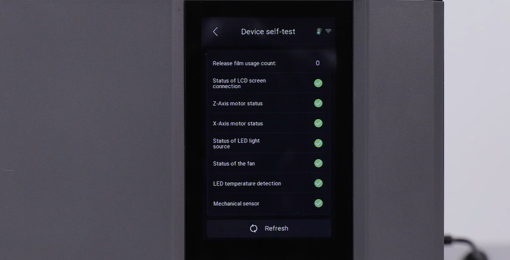
- Power on the printer. The printer is ready for use after its self-inspection.