¶ Tools and Materials
- 2.0mm Allen key x 1
- 2.5mm Allen key x 1
- Phillips screwdriver x 1
- New PCB of power switch x 1
¶ Tutorial Video
https://www.youtube.com/watch?v=VdPExIkrK-s
¶ Instruction
¶ Remove the old PCB of power switch
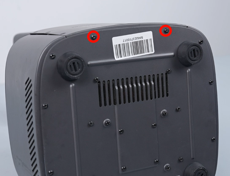
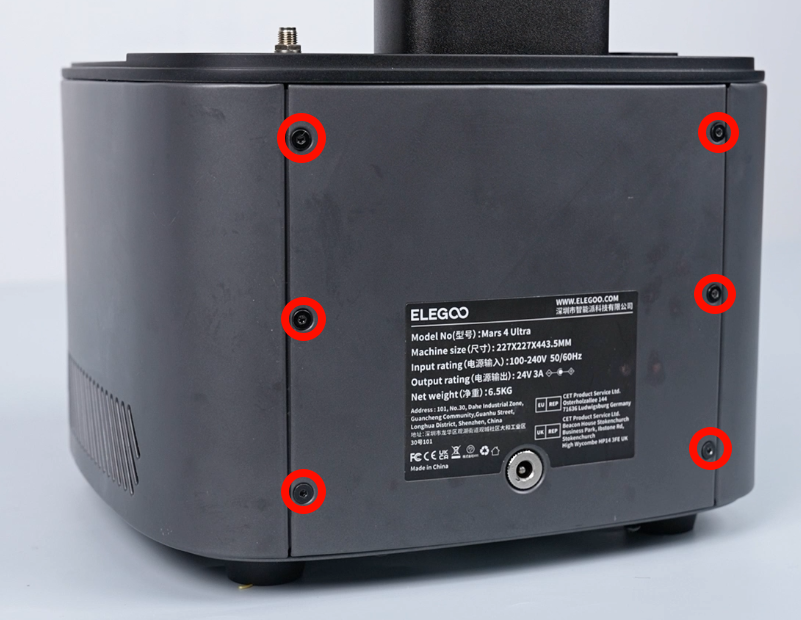
- Using a 2.0mm Allen key, loosen the six screws securing the back cover of the printer.

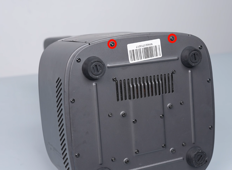
- Using a 2.0mm Allen key, loosen the two screws securing the back cover of the printer. Remove the back cover and lay it flat.
NOTE: There are ribbon cables inside. Take care to remove the cover.
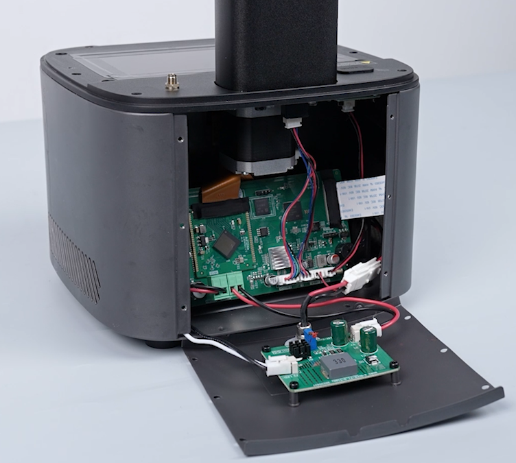
- Disconnect USB adapter cable, cooling fan cable, limit switch cable and motor cable.
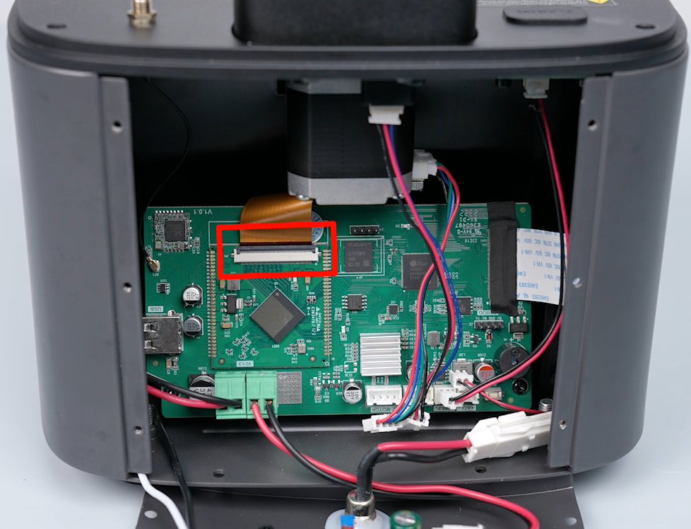
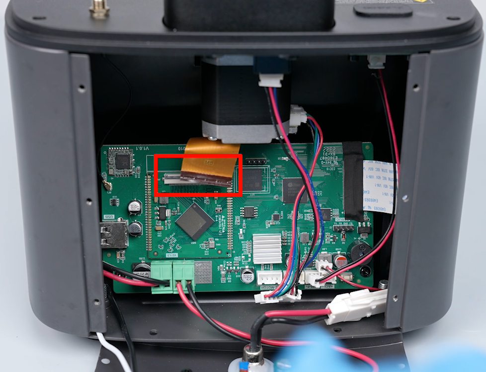
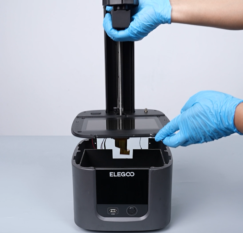
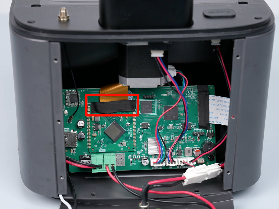
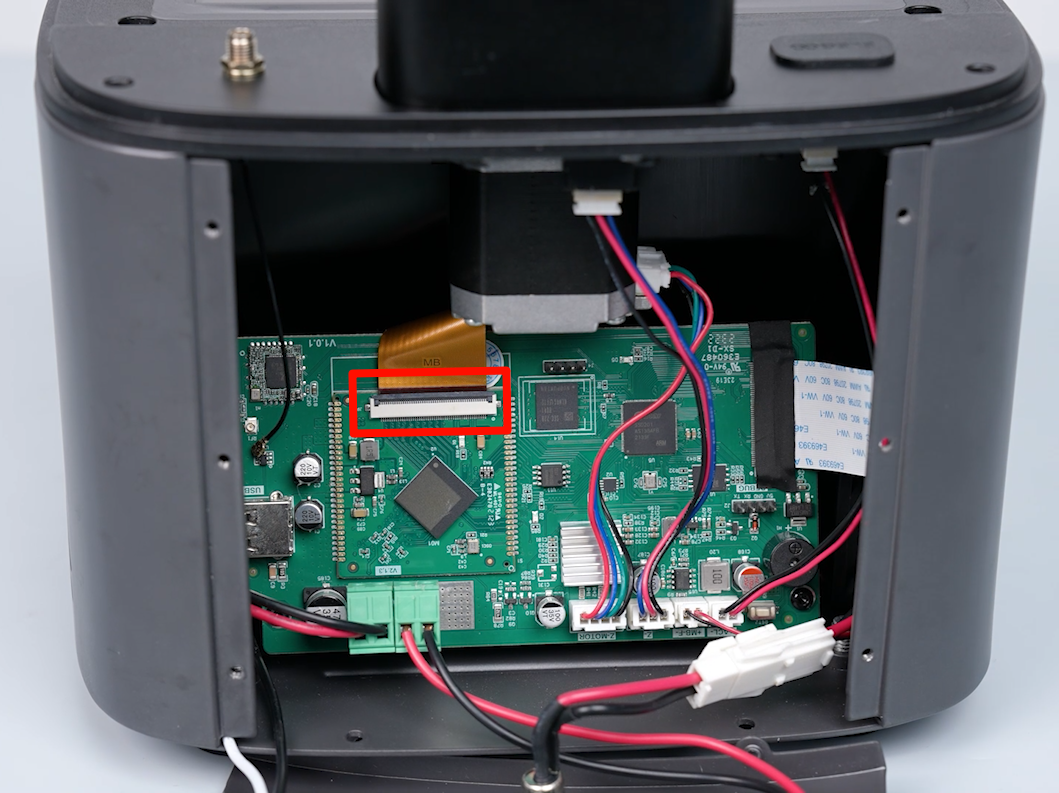
- Tear off the black tape attached to the LCD screen port. Lift the clip of the LCD screen port. Remove the cable of the LCD screen port.
NOTE: Reserve the black tape for subsequent use.
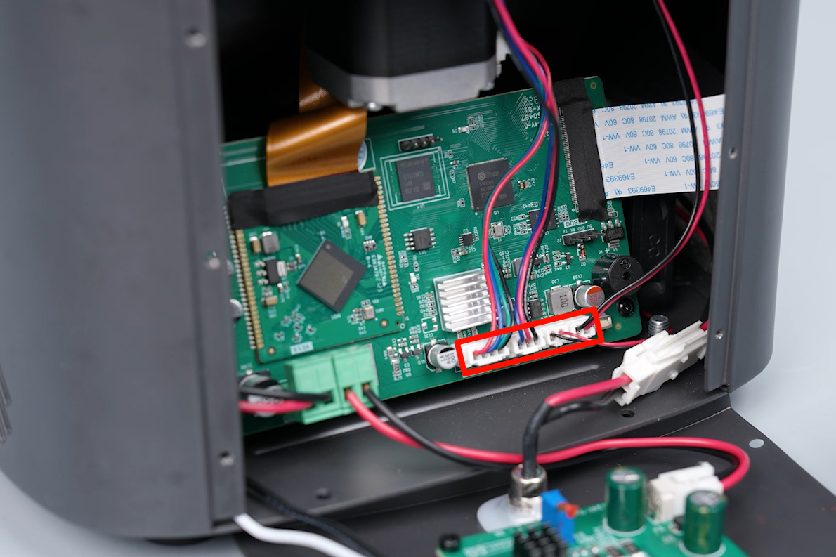
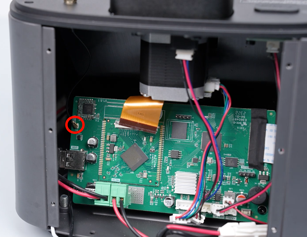
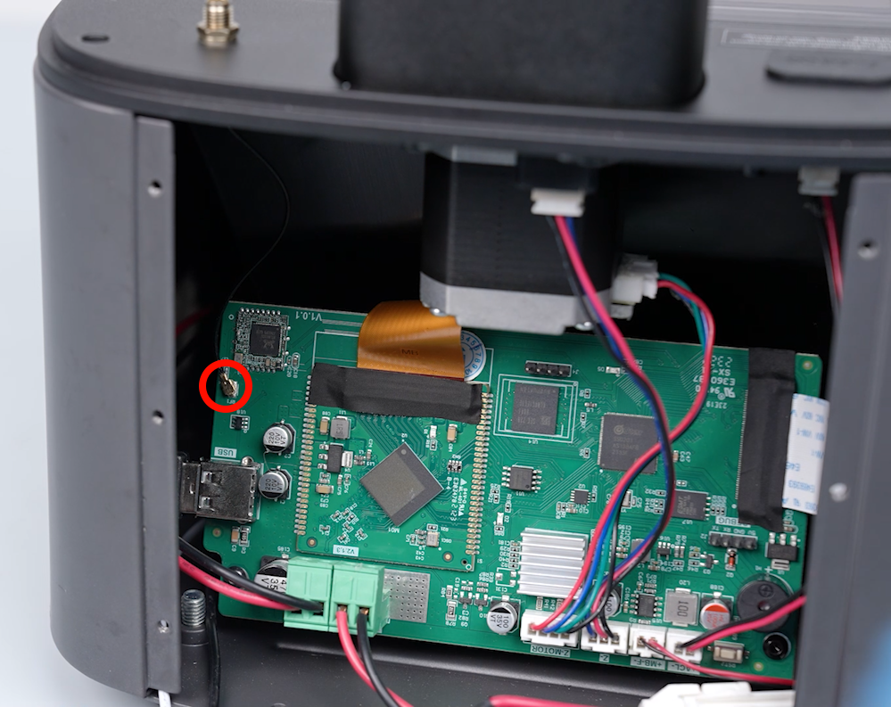
- Disconnect the Wi-Fi cables from the ports on the motherboard.

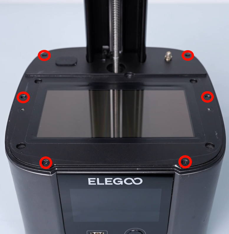
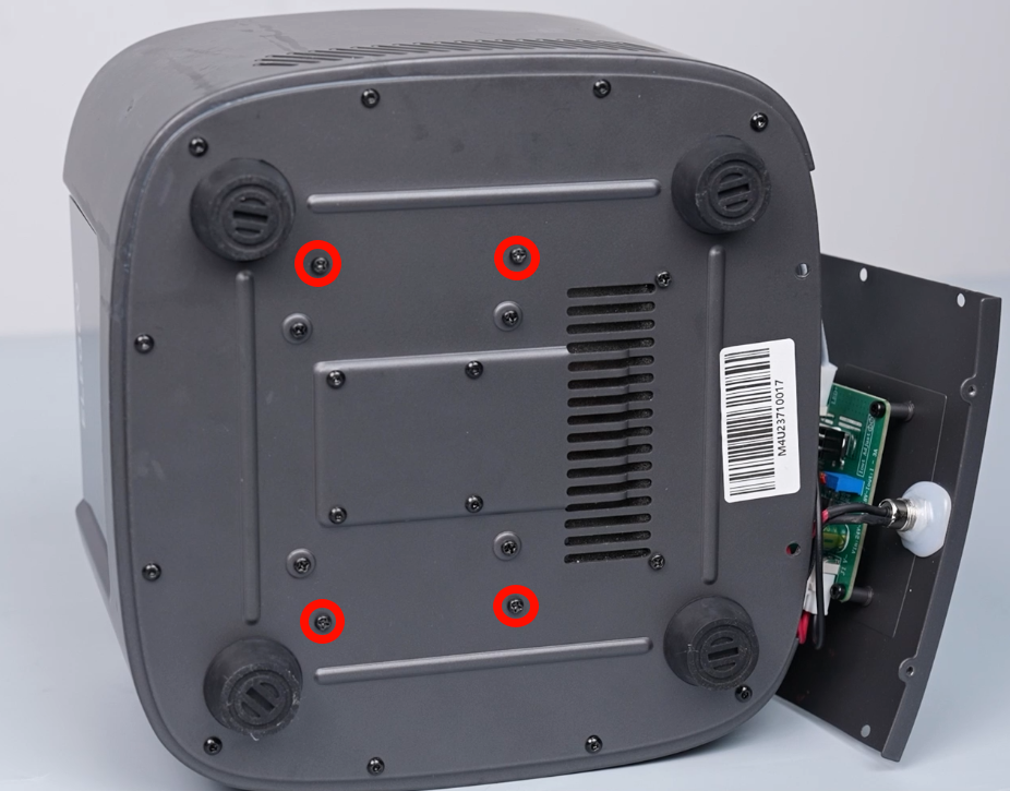
- Using a 2.5mm Allen key, loosen the six screws securing the middle housing.
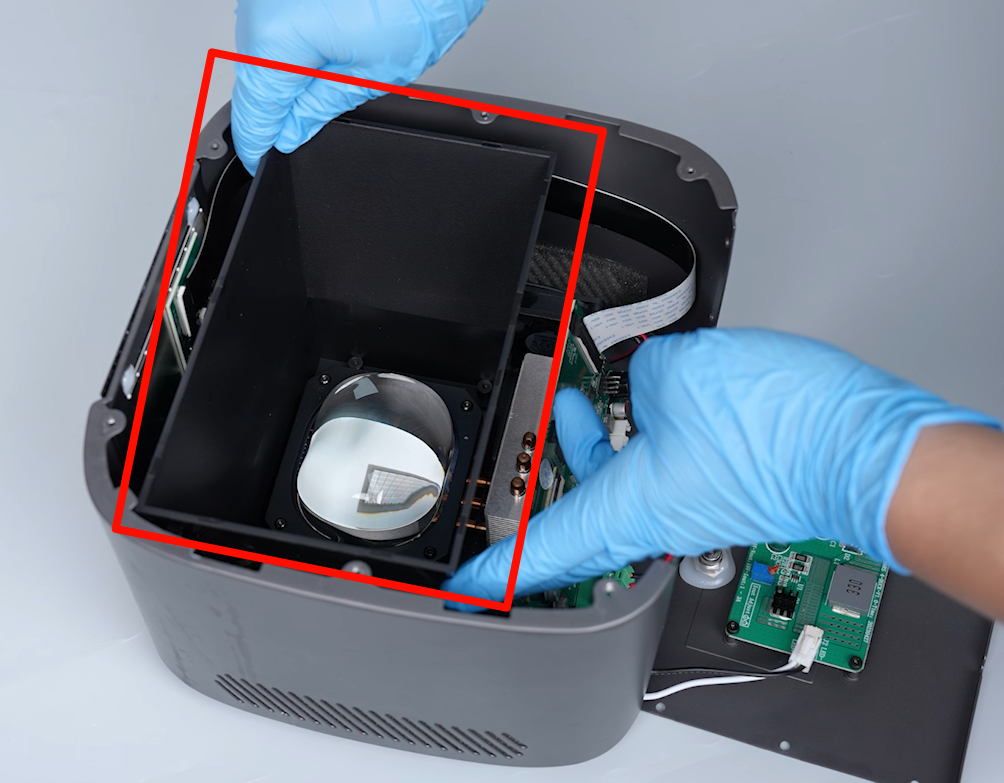
- Lift the middle housing and remove it.
NOTE: Organize the ribbon cables.
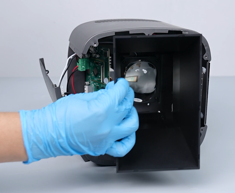
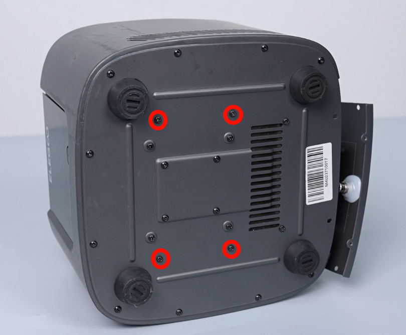
- Using a Phillips screwdriver, loosen the four screws securing the lens shade at the bottom cover of the printer. Remove the lens shade.
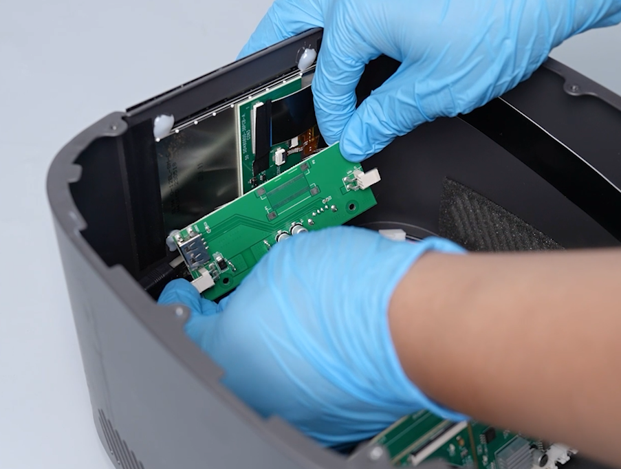
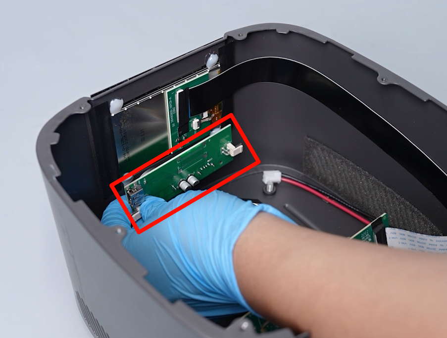
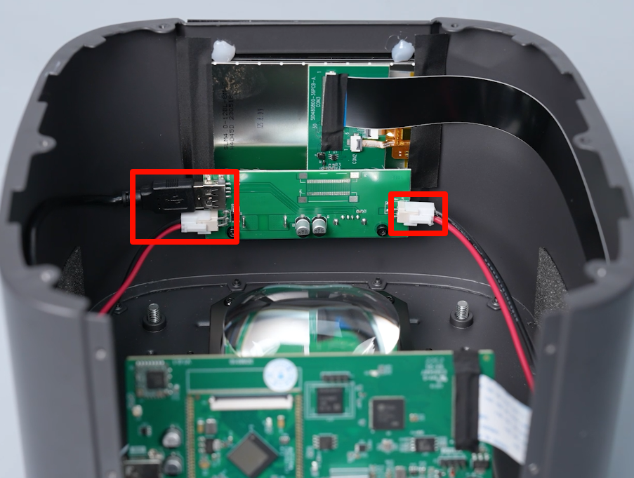
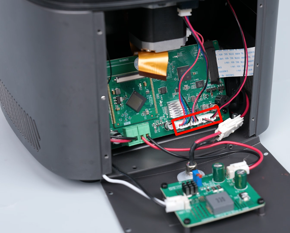
- Disconnect the cables on the PCB of power switch.
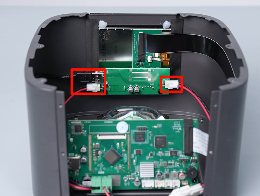
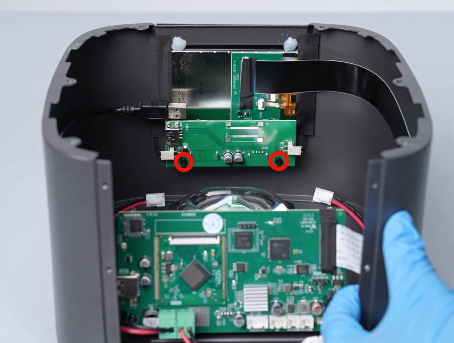
- Using a 2.5mm Allen key, loosen the two screws securing the PCB of power switch. Remove the old PCB of power switch.

¶ Install the new PCB of power switch
- Prepare the new PCB of power switch. Align it with the screw holes and put it in the installation position. Using a 2.5 mm Allen key, tighten the two screws.
- Insert the cables on the PCB of power switch.
- Align the fan shroud with the screw holes and put it in the installation position. Using a Phillips screwdriver, tighten the four screws securing the fan shroud.
- Align the middle housing with the screw holes and put it in the installation position. Using a 2.5mm Allen key, tighten the six screws securing the middle housing.
NOTE: Organize the cables inside the printer to avoid any damage.

- Reconnect the motor cable to the Z-MOTOR port on the motherboard. Reconnect the limit switch cable to the Z- port on the motherboard. Reconnect the cooling fan cable to the MB-F port on the motherboard. Reconnect the USB adapter cable to the ACL port on the motherboard.
- Insert the LCD screen ribbon cable into the port on the motherboard. Adhere the black tape to the LCD ribbon cable port.
Note: The LCD screen ribbon cable has a fixed installation position.
- Insert the Wi-Fi cables into its port on the motherboard.
- Align the back cover with the screw holes and put it in the installation position. Using a 2.0mm Allen key, tighten the six screws securing the back cover.
- Using a 2.0mm Allen key, tighten the two screws securing the lower part of the back cover of the printer.
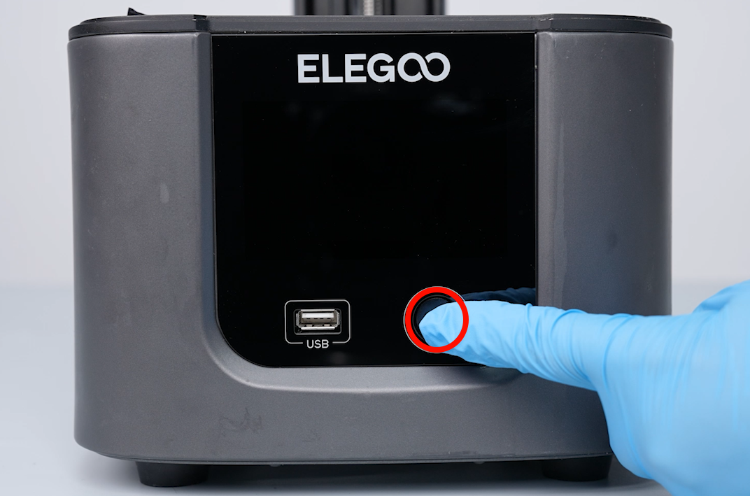
- Power on the printer. The printer is ready for use after the touchscreen works normally.