¶ Tools and Materials
- 2.0mm Allen key x 1
- 2.5mm Allen key x 1
- Cable ties
¶ Tutorial Video
¶ Instruction
¶ Remove the old UV LED board
- Power off the printer and unplug the power cord.
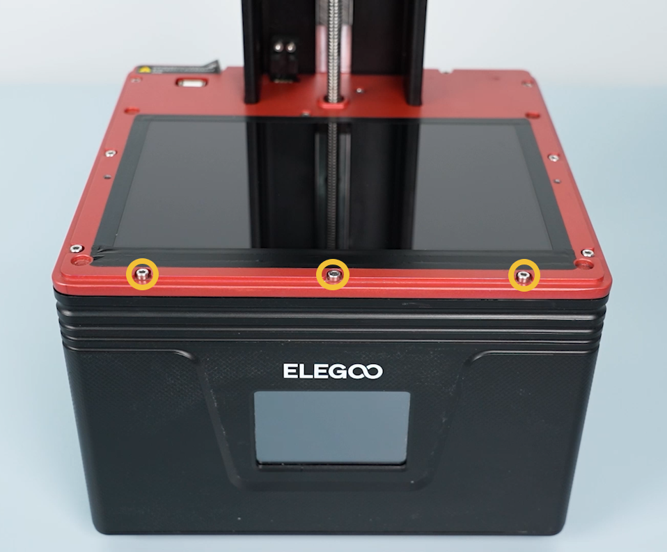
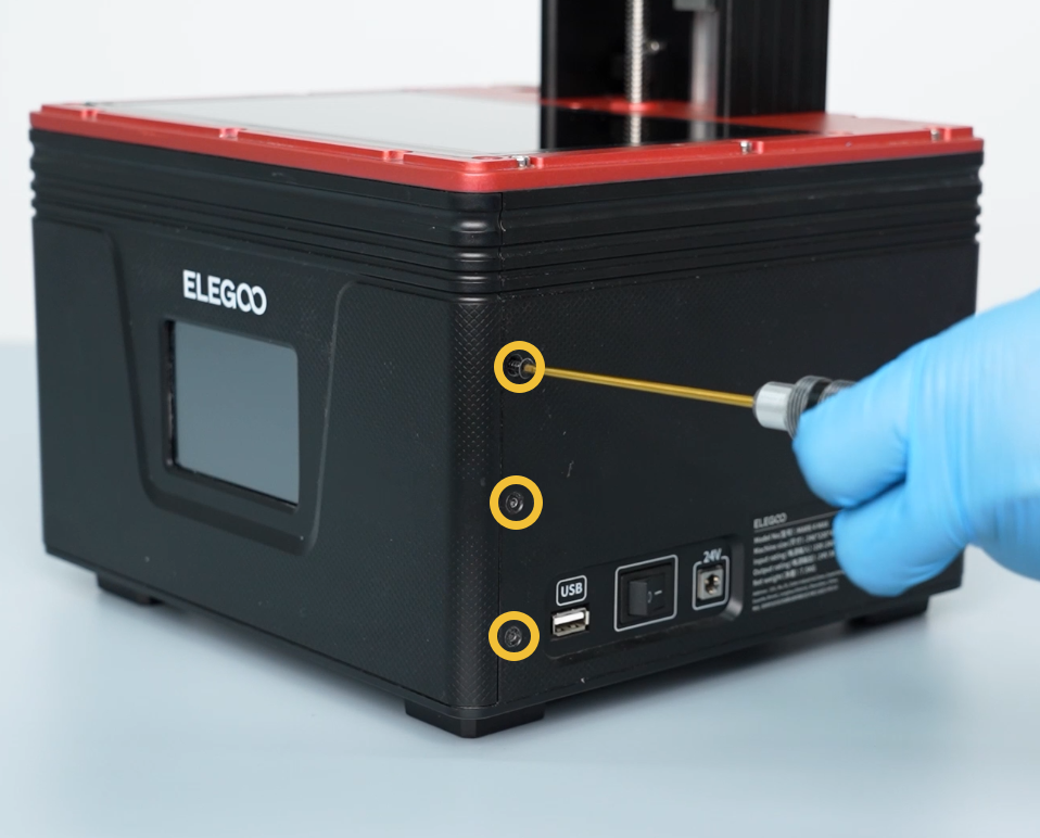
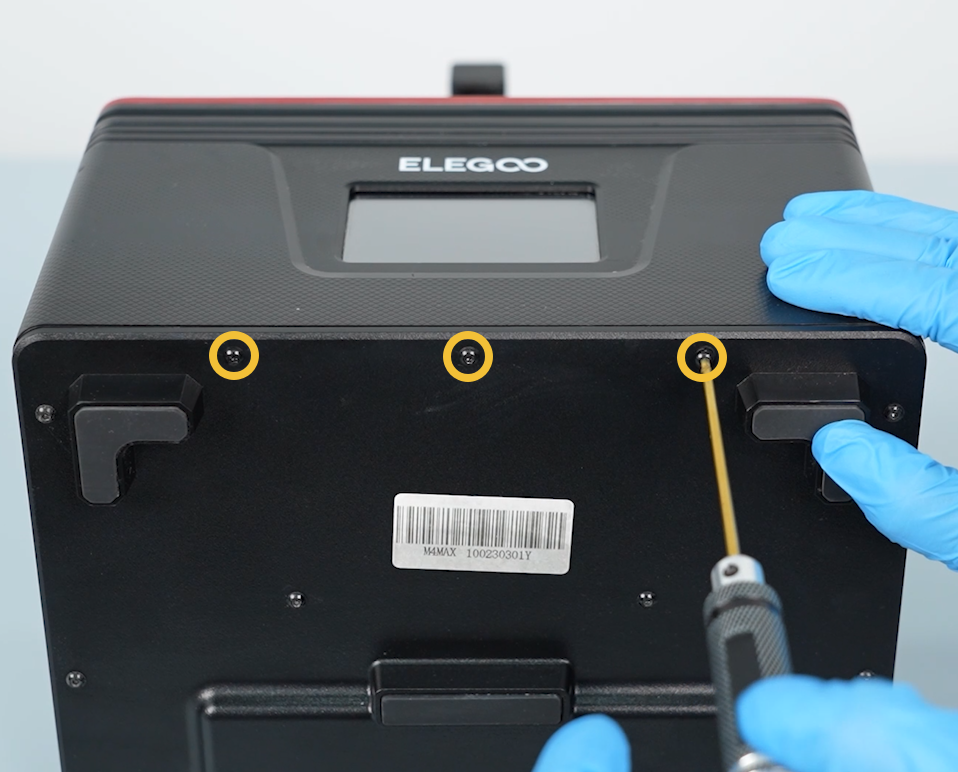
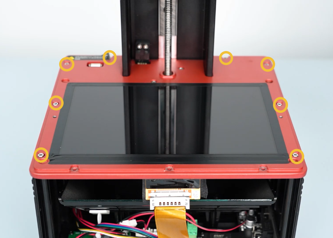
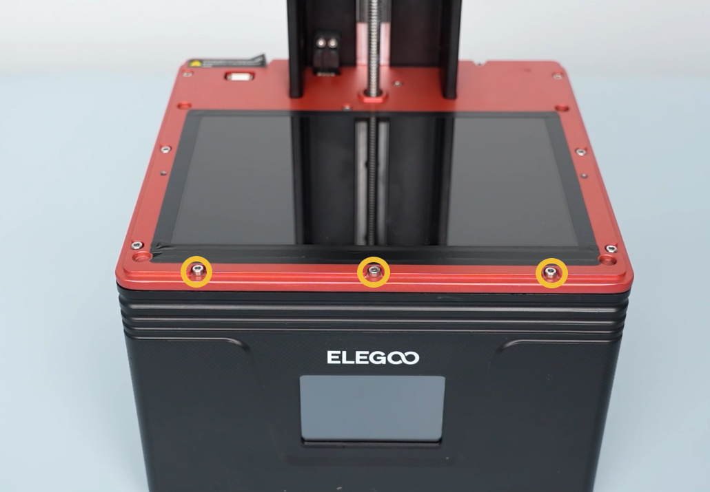
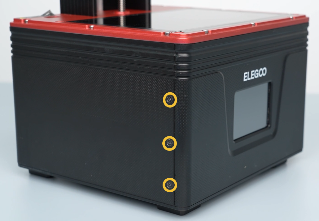
- Loosen the three screws fixed at the upper part of the front cover using a 2.5mm Allen key.
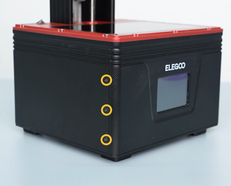
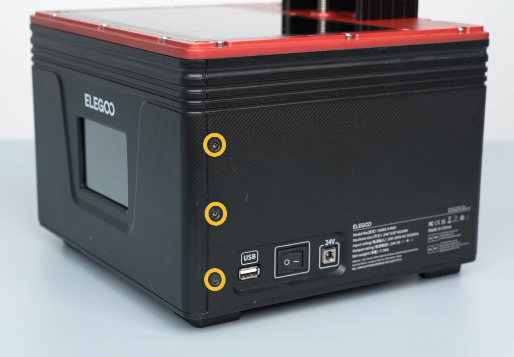
- Loosen the three screws securing the left, right and bottom side of the front cover using a 2.0mm Allen key.
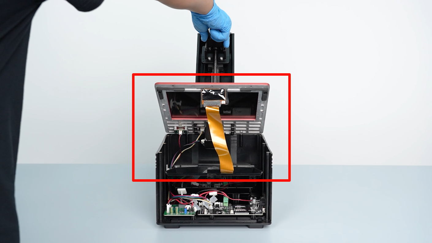
Note: There are ribbon cables inside. Take care to remove the cover.
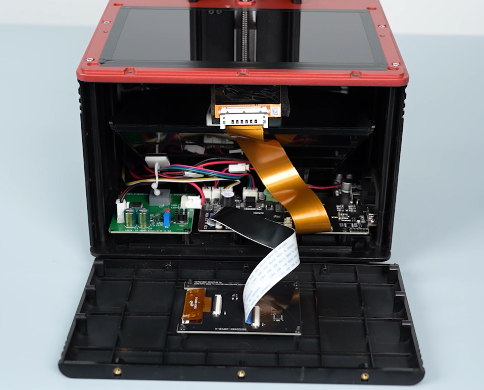
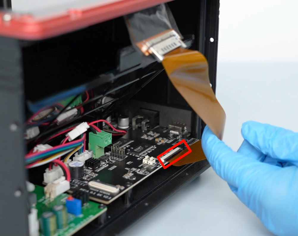
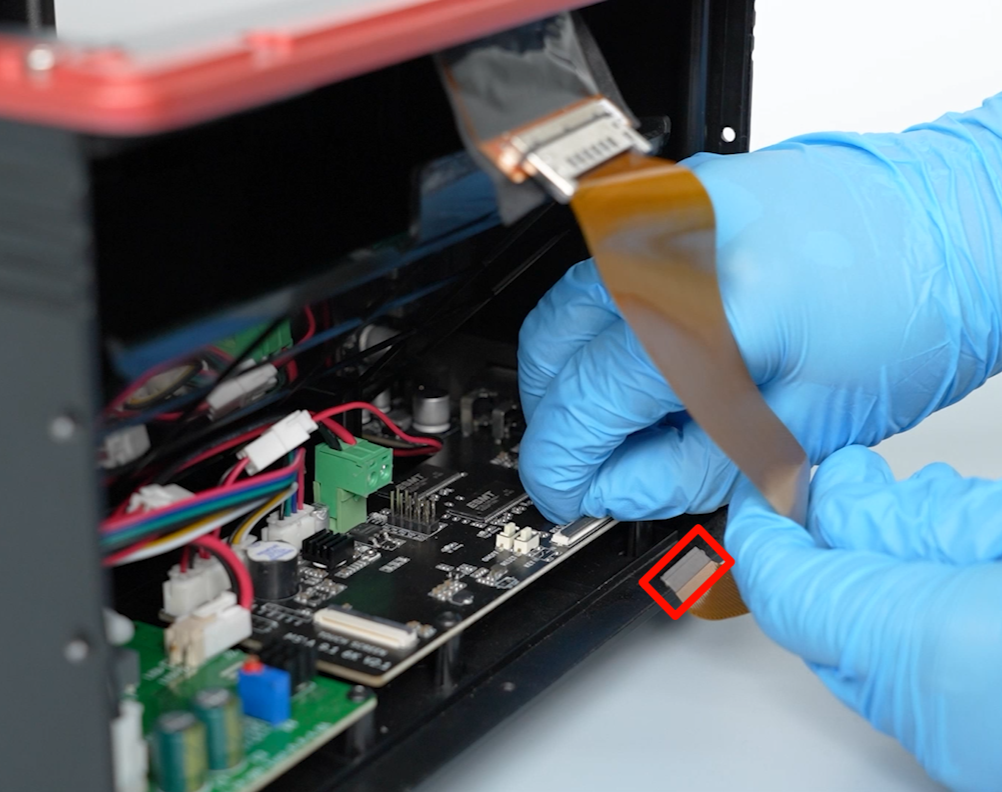
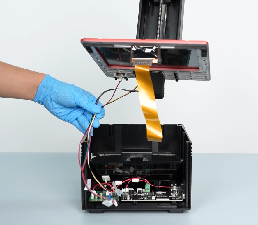
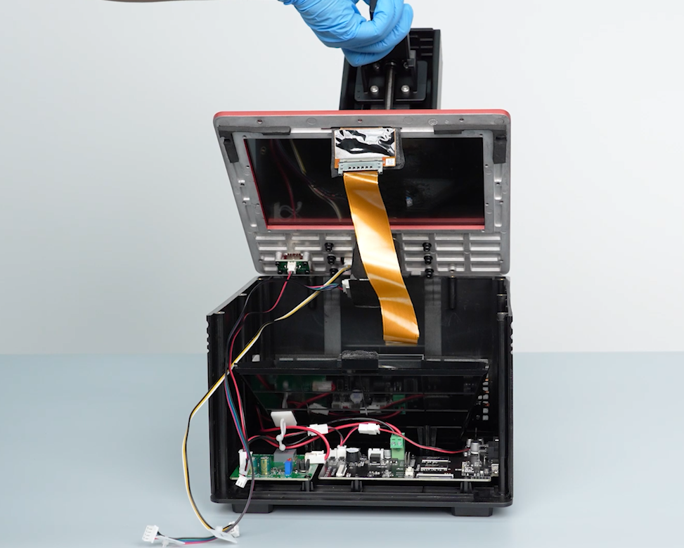
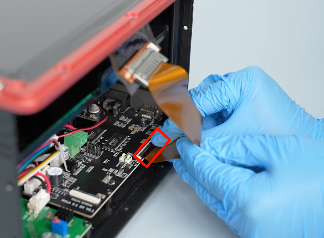
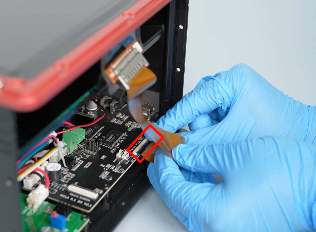
- Lift the clip of the touchscreen cable port on the motherboard and remove the cable and the front cover.
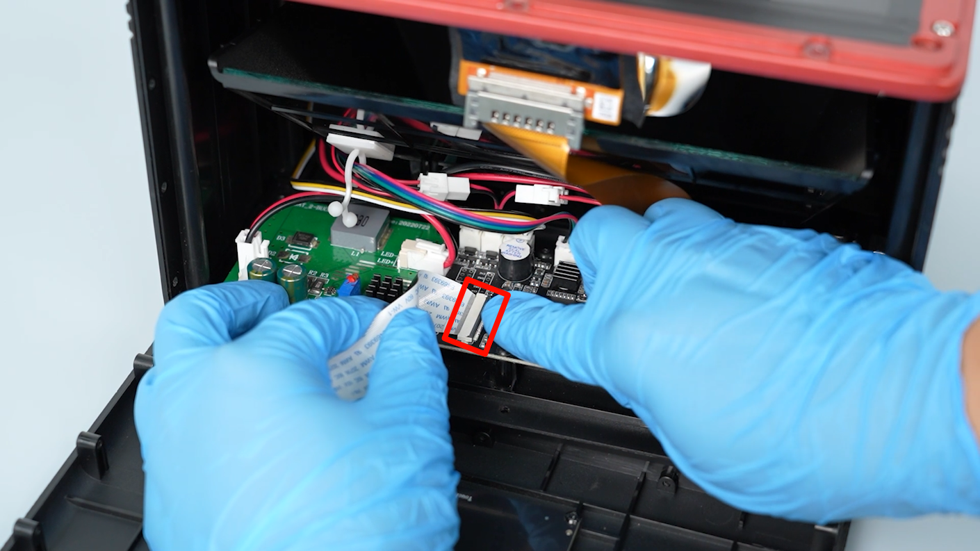
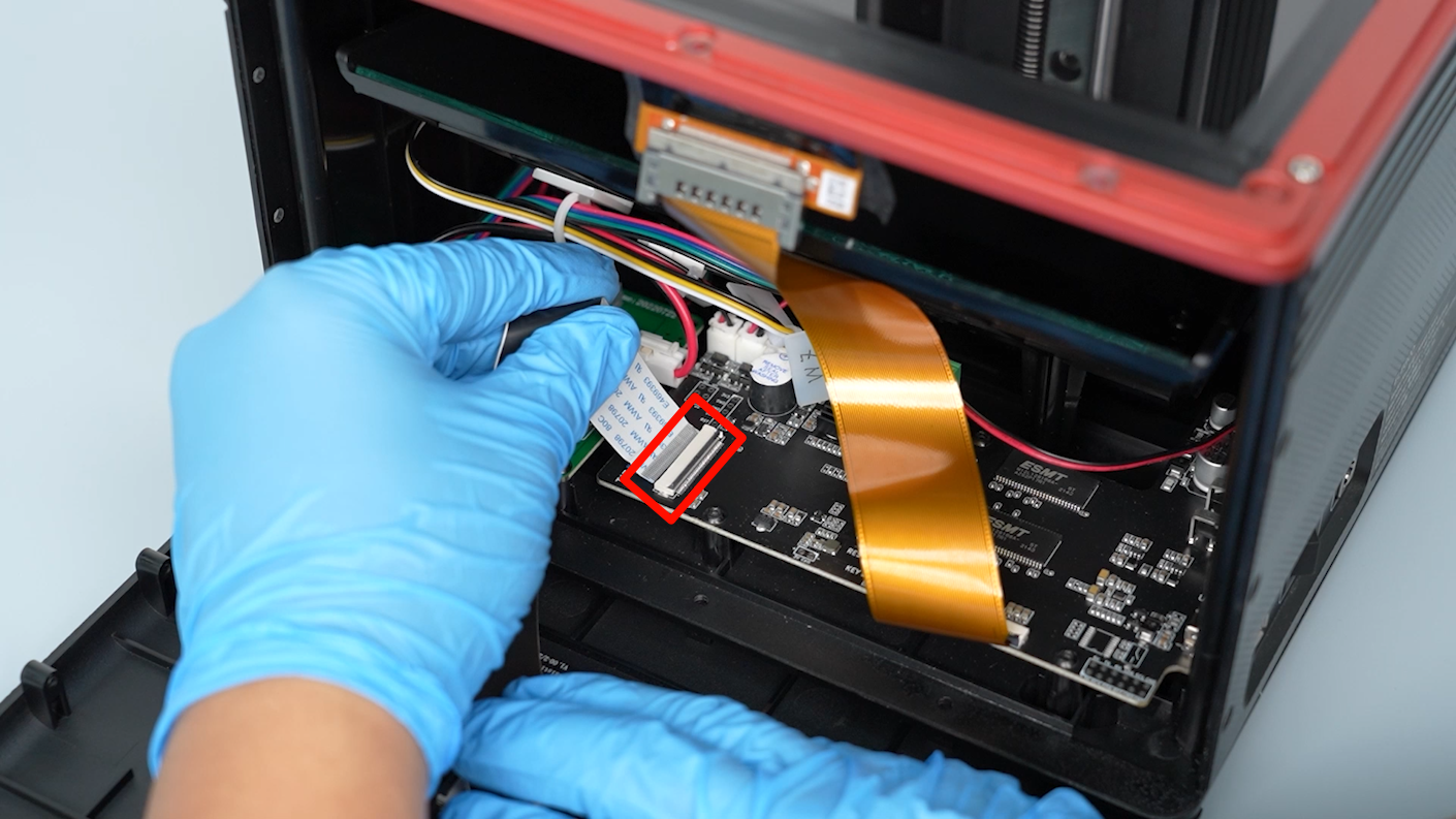
- Lift the touchscreen cable port clip on and remove the LCD screen cable.
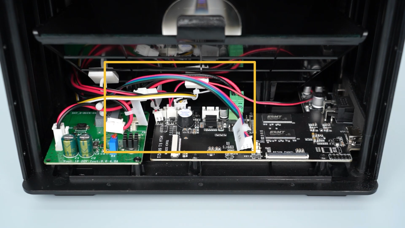
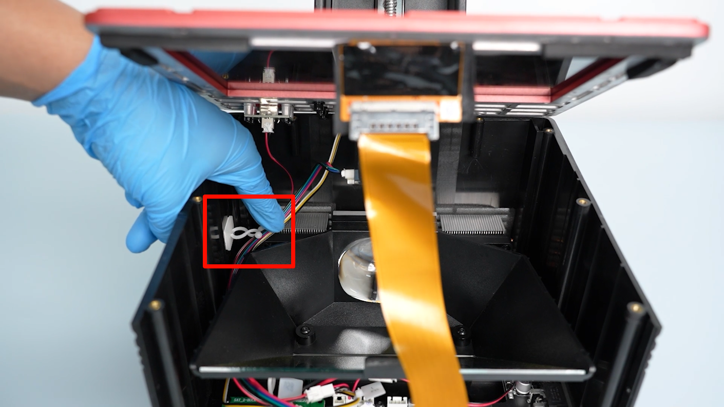
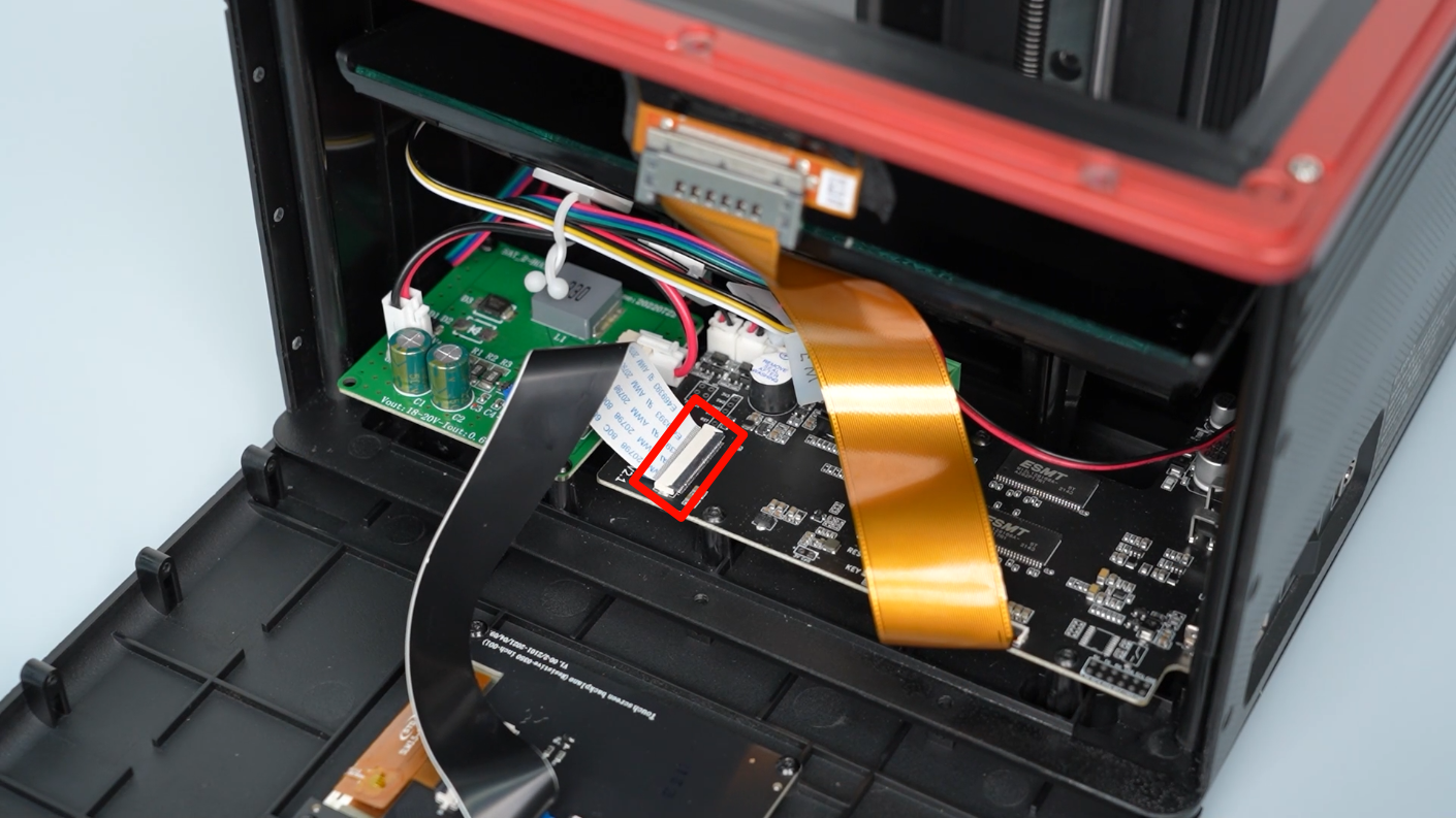
- Using labels or label ties, mark the cables on the motherboard for easy re-insertion later.
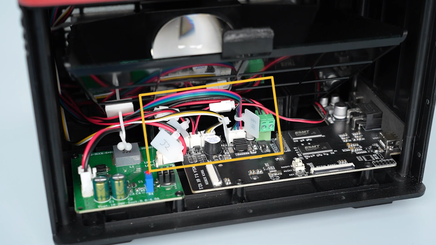
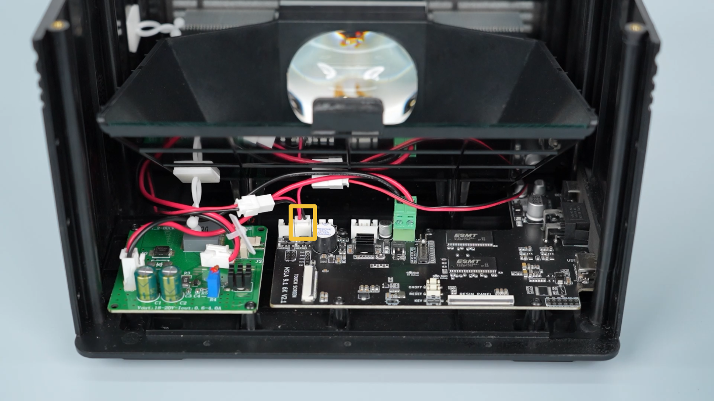
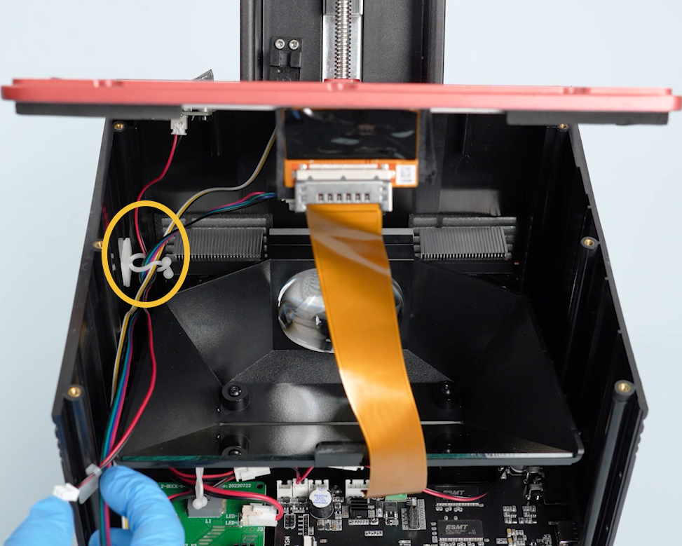
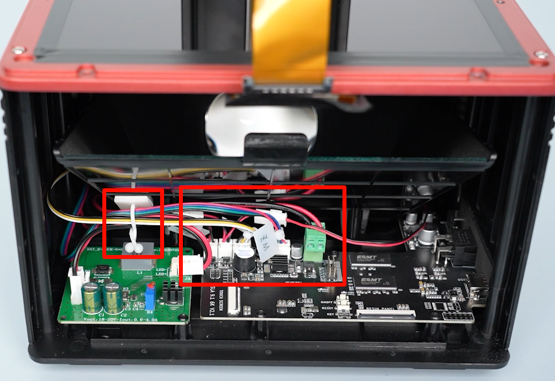
- Disconnect the cables of the UV LED board, air purifier, limit switch and Z-axis motor on the motherboard. Remove the cables from the cable clip.
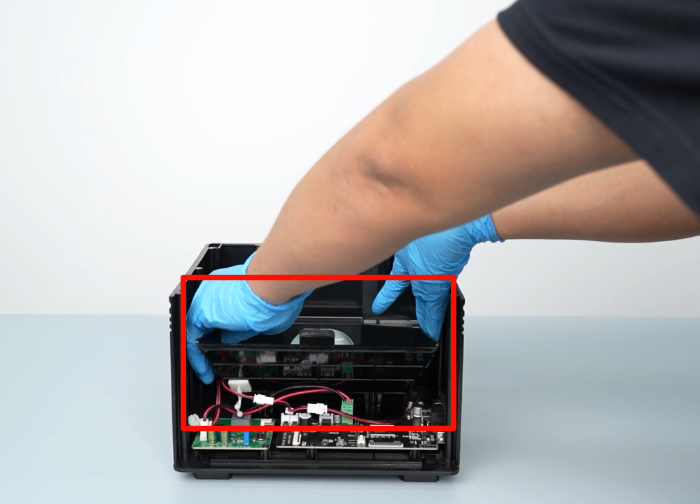
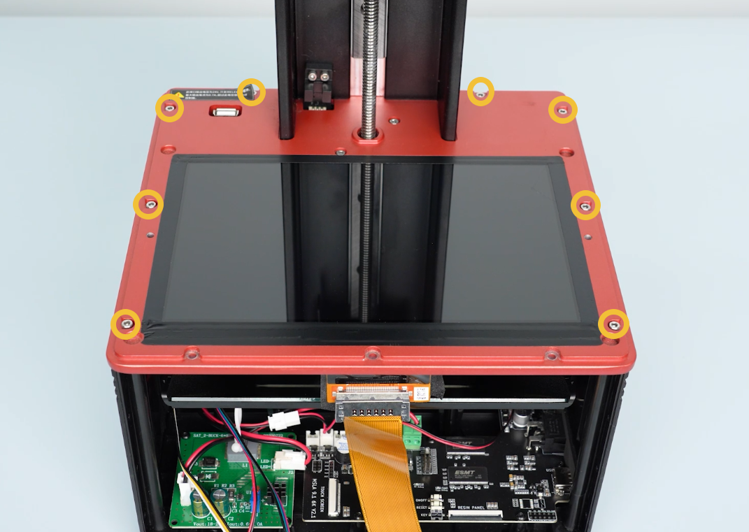
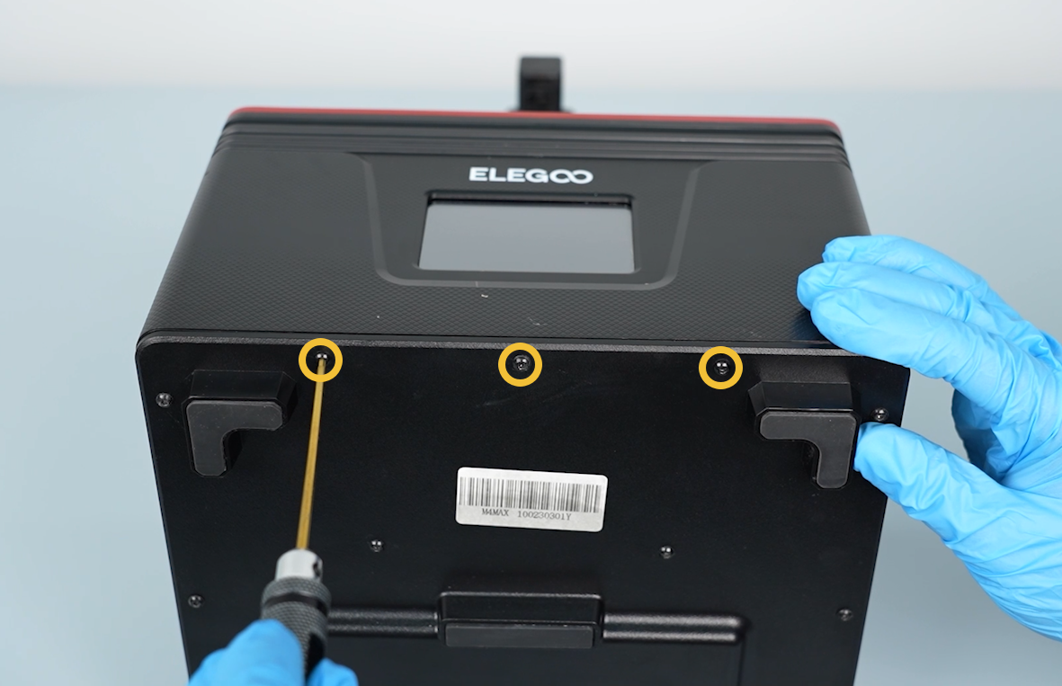
- Loosen the eight screws securing the middle housing using a 2.5mm Allen key.
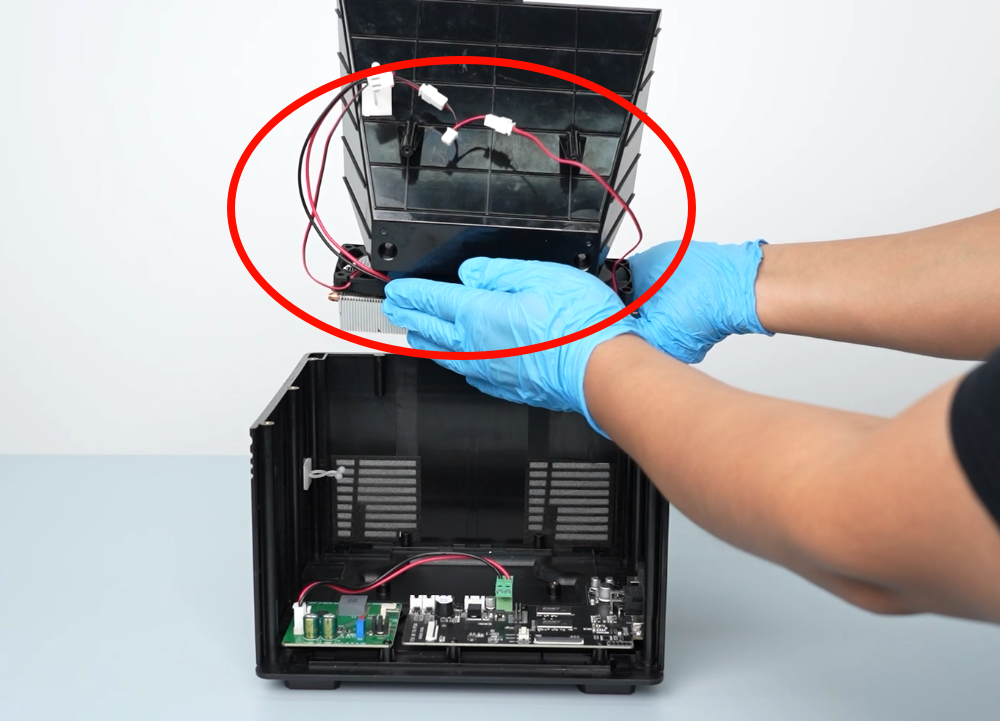
- Tilt the middle housing back approximately 45°. Take out the cables from the inner clip of the base.
- Organize the ribbon cables. Lift the middle housing.
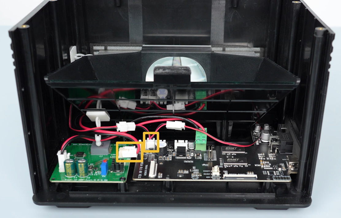
- Unplug the cables of the cooling fan.
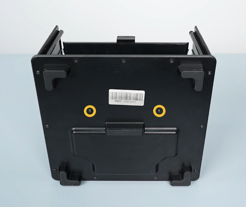
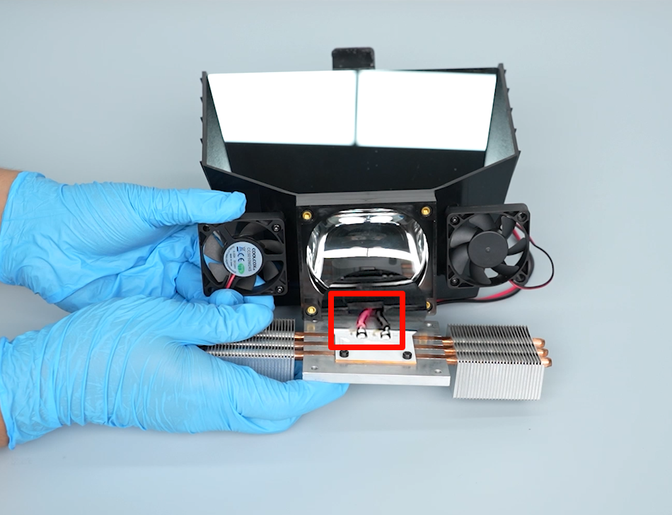
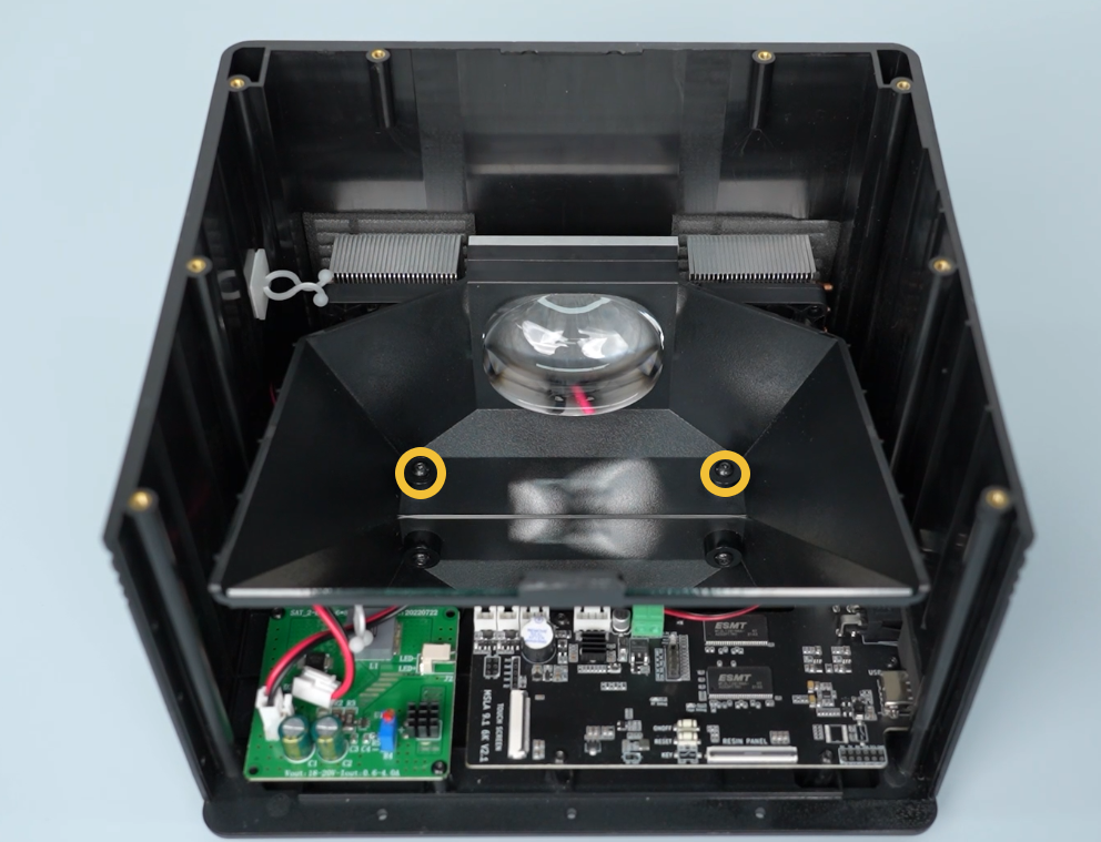
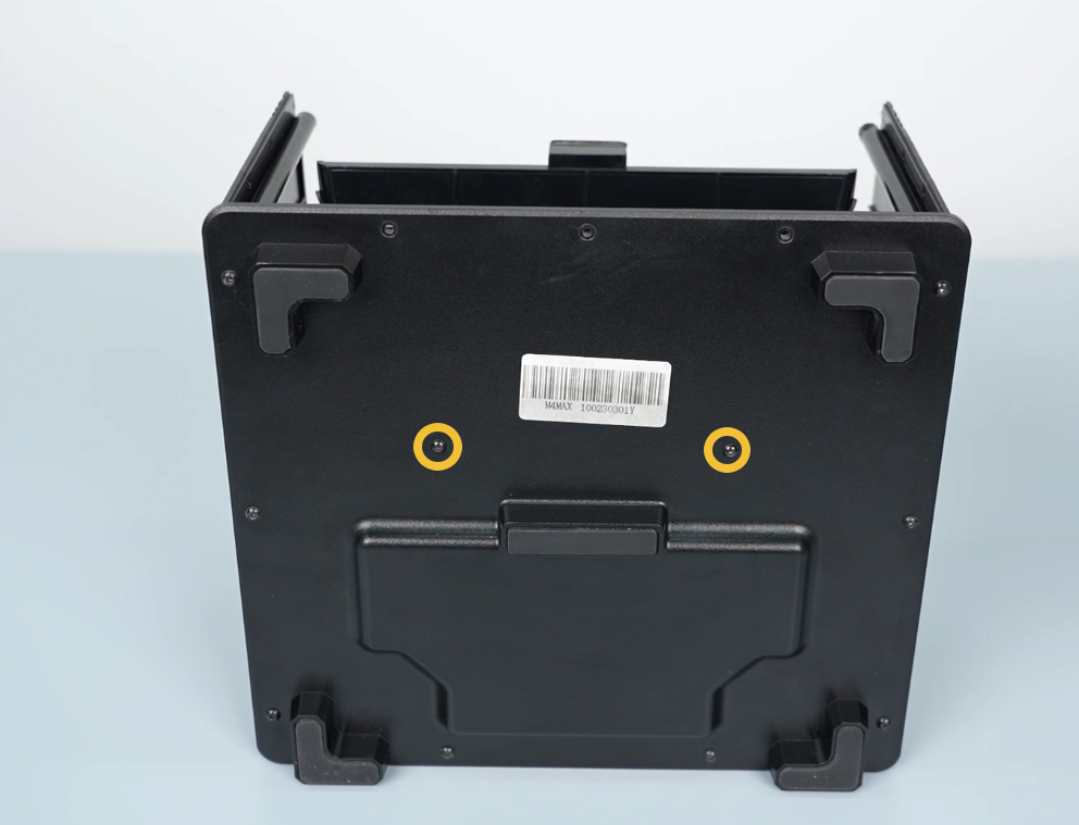
- Loosen the two screws securing the lens shade at the bottom cover of the printer using a 2.0mm Allen key.
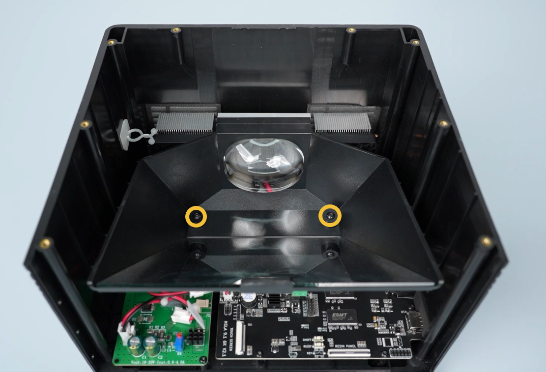
- Loosen the two screws securing screws inside the lens shade using a 2.5mm Allen key.
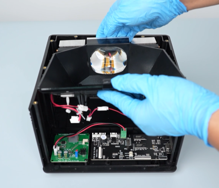
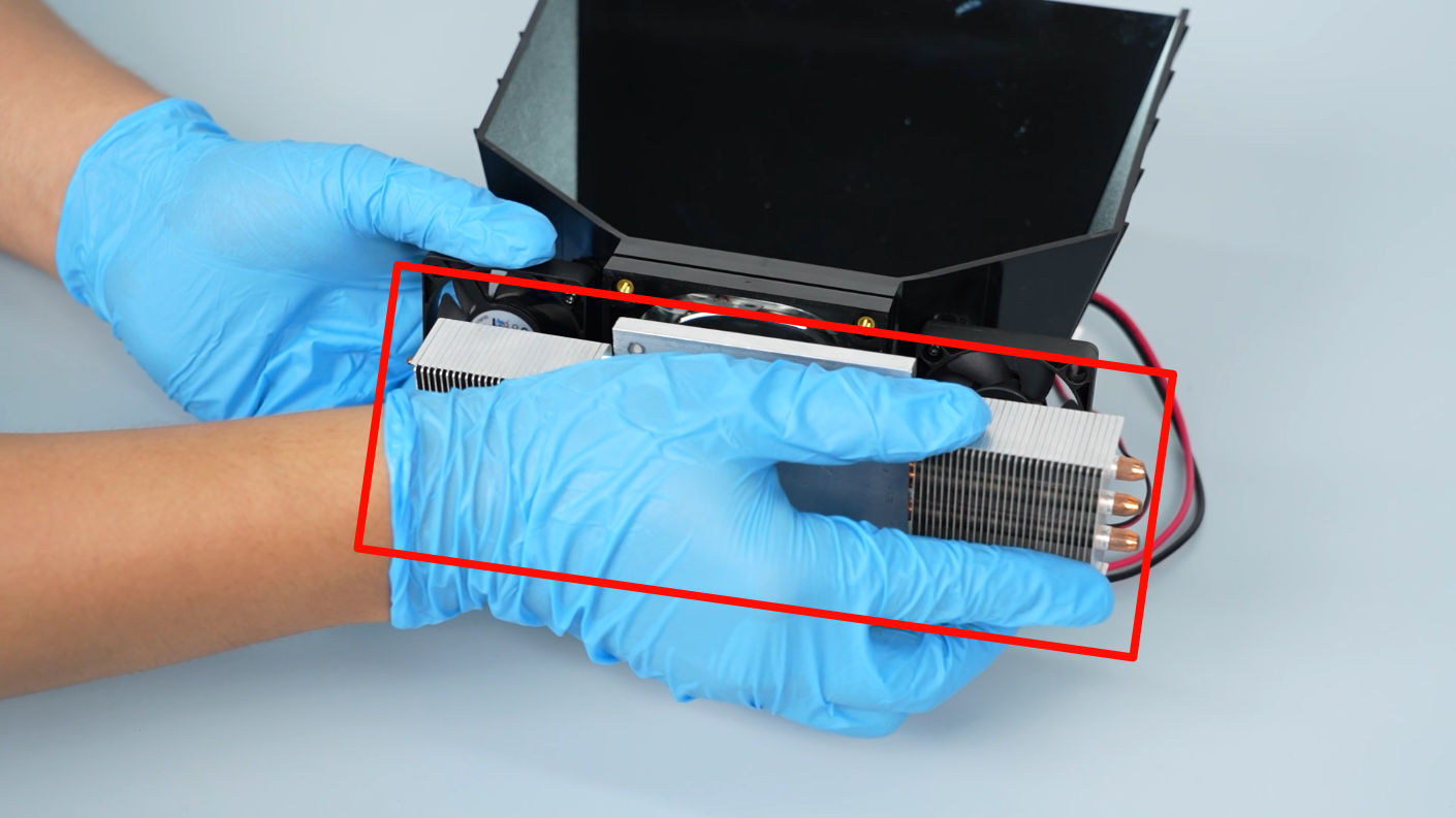
- Lift the lens shade and the UV LED board assembly.
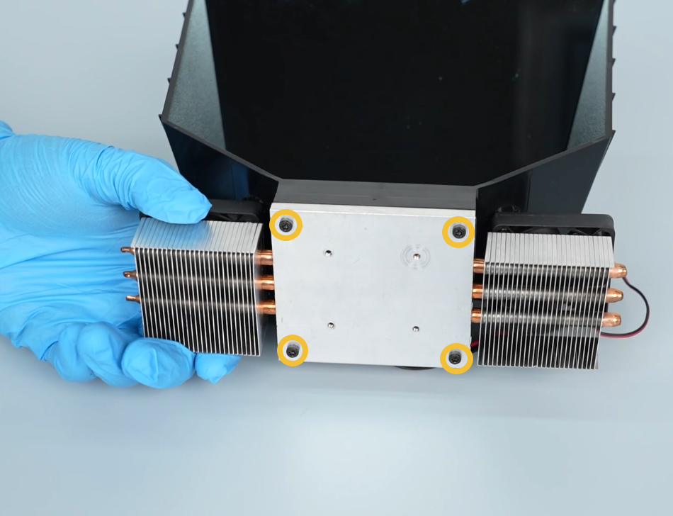
- Loosen the four screws securing the heatsink using a 2.5mm Allen key.
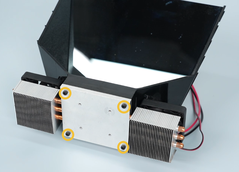
- Remove the heatsink.
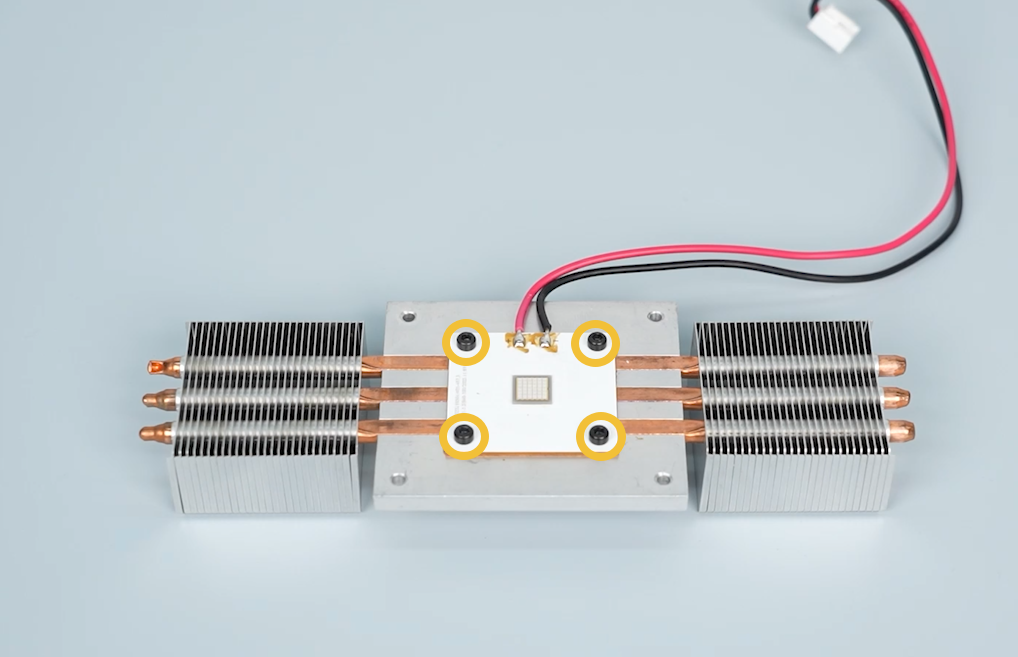
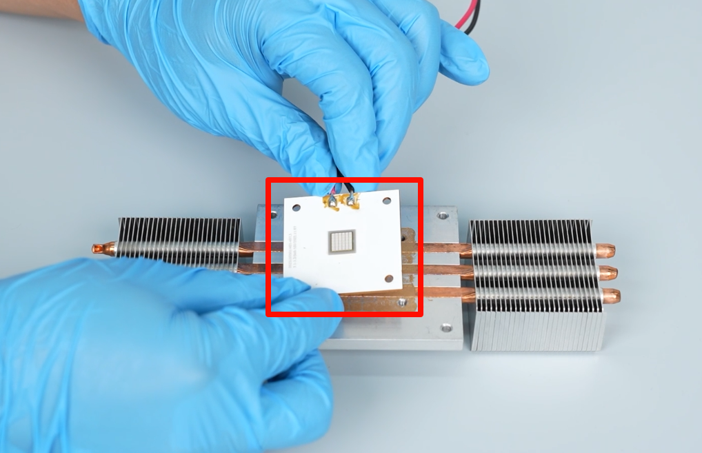
- Loosen the four screws securing the UV LED board using a 2.5 mm Allen key. Remove the board.
¶ Install the new UV LED board
- Prepare the new UV LED board.
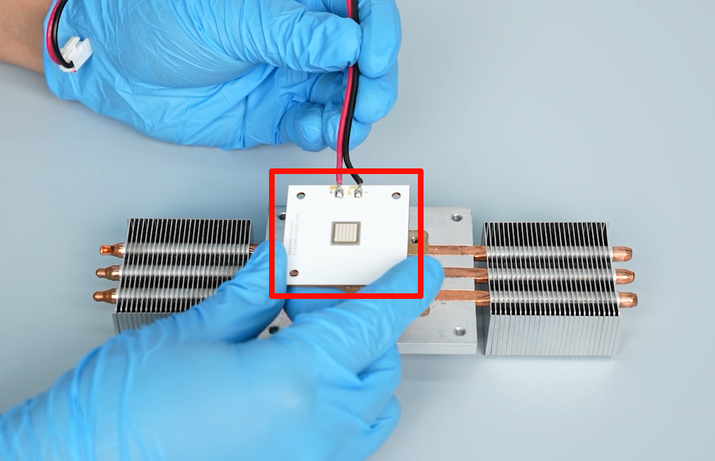
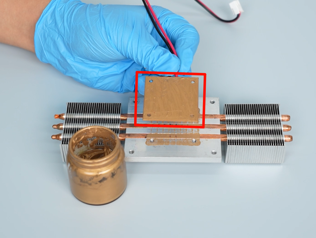
- Apply an appropriate amount of thermal grease to the back of the UV LED board.
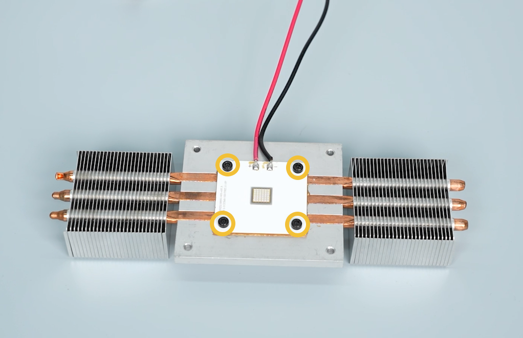
- Align the UV LED board with the screw holes and put it the motherboard in the installation position. Tighten the four screws securing the UV LED board using a 2.5 mm Allen key.
- Wipe off any spilled thermal grease around the UV LED board using a paper towel.
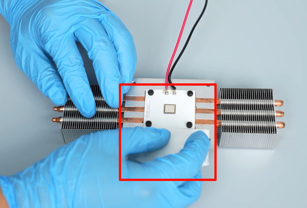
- Prepare the lens shade. Align the heatsink with the screw holes and put it in the installation position. Tighten the four screws securing the heatsink using a 2.5mm Allen key.
Note: Align the cable of the UV LED board with the cable groove.
- Prepare the lens shade and UV LED board assembly. Organize the cables of the UV LED board and the cooling fan to avoid being pressed.
- Align the lens shade and the UV light board with the screw holes and put them in the installation position.
- Tighten the two screws securing screws inside the lens shade using a 2.5mm Allen key.
- Tighten the two screws securing the lens shade on the bottom cover of the printer using a 2.0 mm Allen key.
- Insert the cables of the cooling fan and the UV LED board into the port on the motherboard.
- Align the middle housing with the screw holes on the base and put it in the installation position. Tilt the middle housing back approximately 45°. Insert the cables into the inner clip of the base.
- Organize the cables. Lay the middle housing flat. Tighten the eight screws securing the middle housing using a 2.5 mm Allen key.
- Insert the cables of the Z-axis motor, limit switch and air purifier into the motherboard. Organize the cables and secure them with cable clips.
- Insert the LCD cable into the motherboard port and press the clip to secure.
Note: The LCD screen cable has a fixed installation position.
- Prepare the front cover. Insert the ribbon cables of the touchscreen into the motherboard port. Press the clip to secure.
Note: The touchscreen ribbon cables have a fixed installation position.
- Align the front cover with the screw holes and put it in the installation position. Tighten the three screws securing the upper part of the front cover.
- Tighten the three screws securing the left, right and bottom side of the front cover using a 2.0mm Allen key.
- Power on the printer. Select Tool - Caliberate - Next on the touchscreen. Observe the self-check pattern lighting up on the exposure screen. After re-leveling the printer, it can be used normally.