¶ Tools and Materials
- A 2.5 mm Allen wrench
- A 2.0 mm Allen wrench
- Marker pen
- Dust-free cloth
¶ Tutorial Video
Coming soon.
¶ Instruction
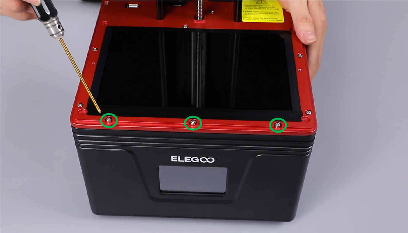
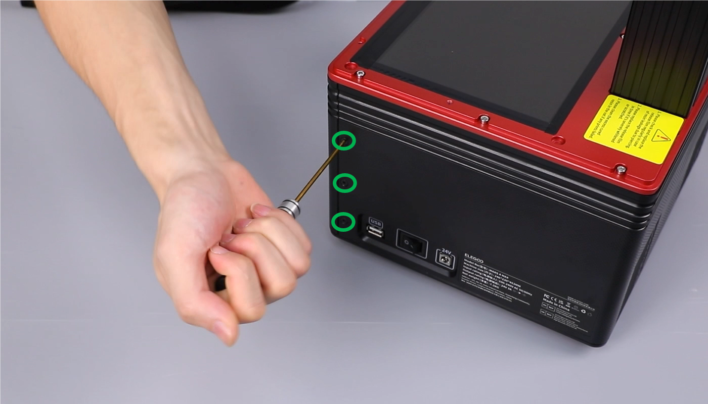
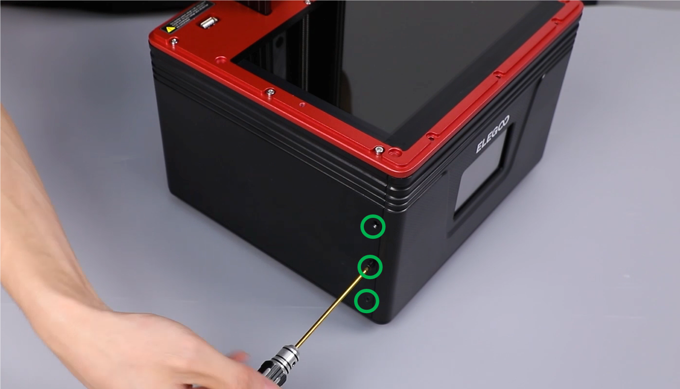
- Using a 2.5 mm Allen key, loosen the three screws securing the upper part of the front cover of the printer base.
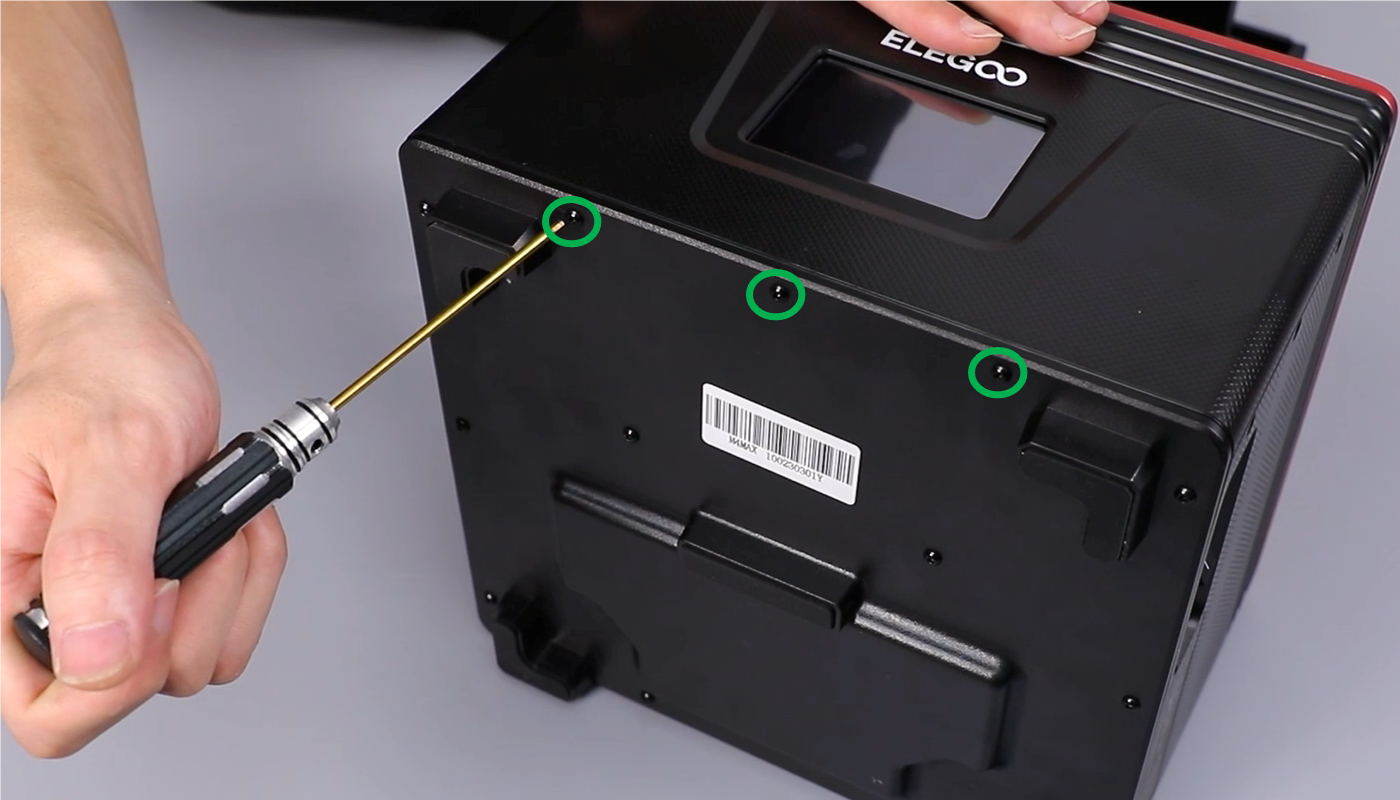
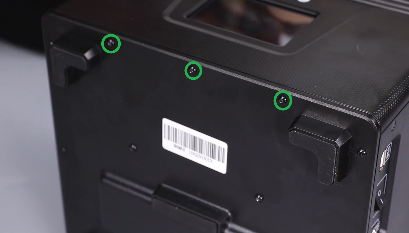
- Using a 2.0 mm Allen key, loosen the three screws securing the left part of the front cover of the printer base.

- Using a 2.0 mm Allen key, loosen the three screws securing the right part of the front cover of the printer base.
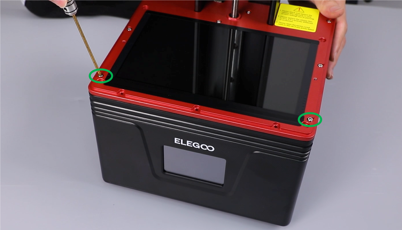
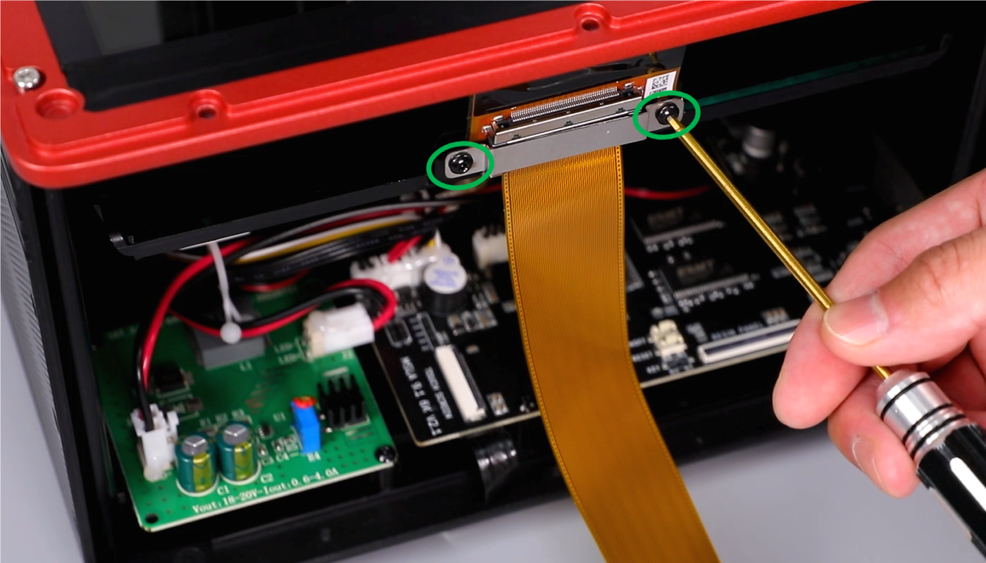
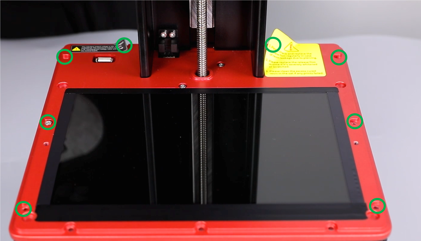
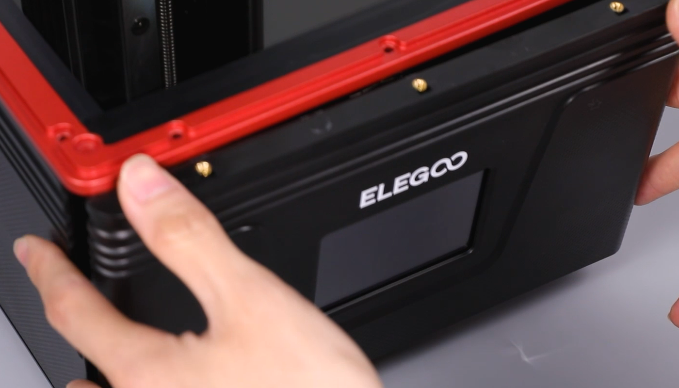
- Using a 2.0 mm Allen key, loosen the three screws securing the lower part of the base front cover. Using a 2.5mm Allen key, loosen the two screws at the right and left side of the red middle housing. Remove the touchscreen and lay it flat on the table.
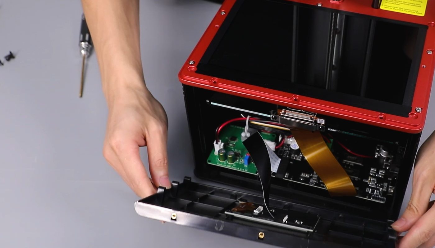
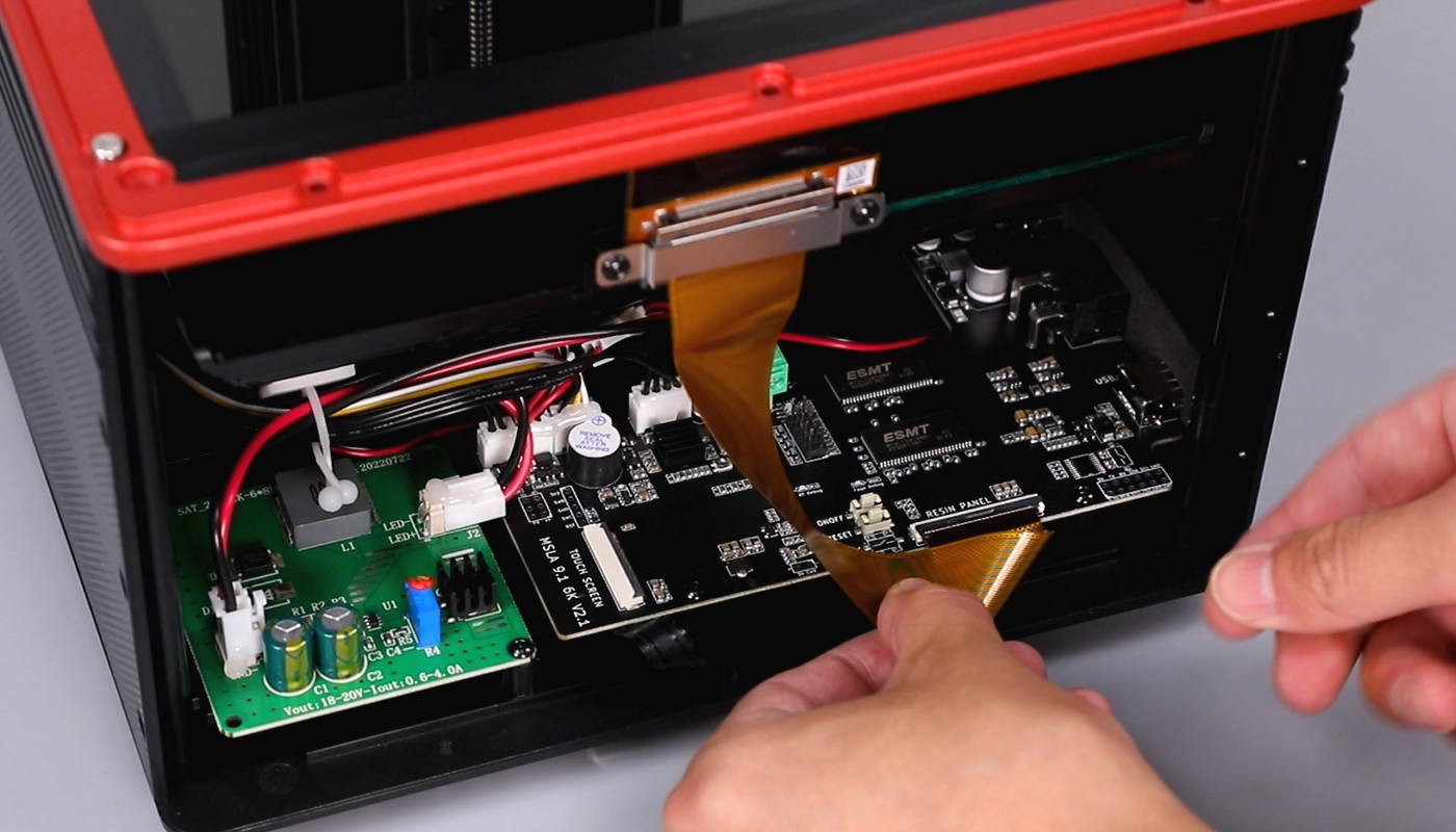
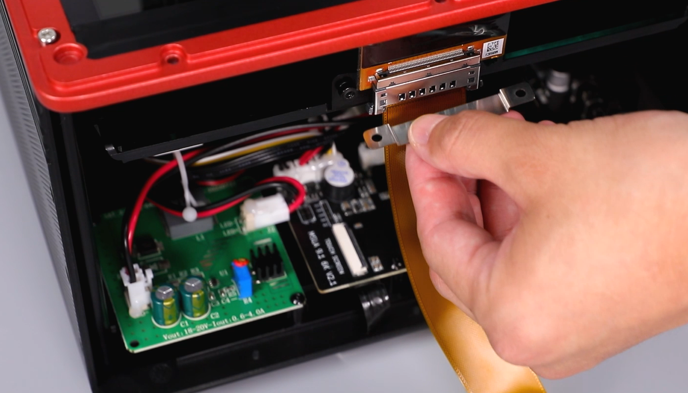
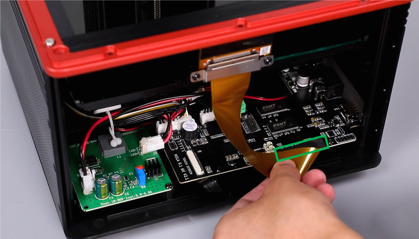
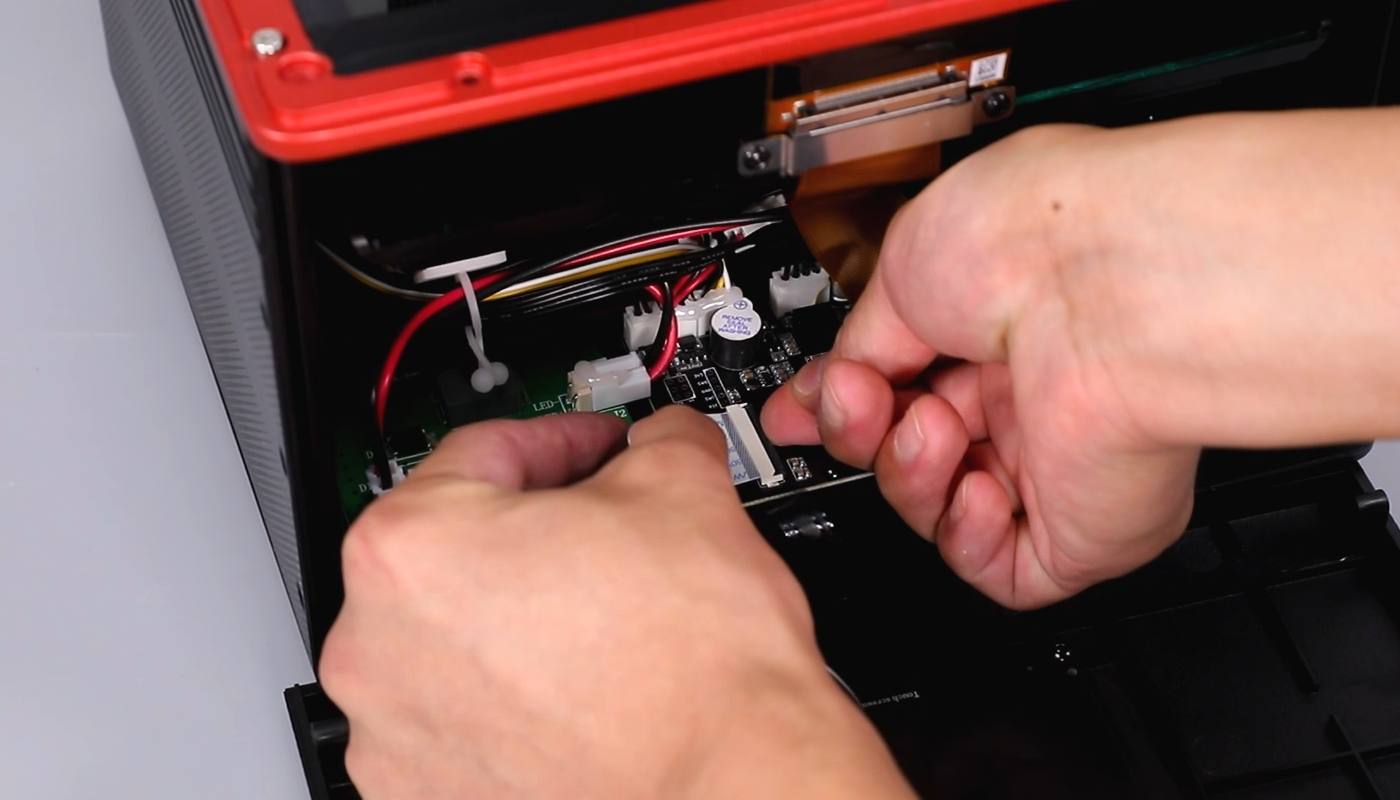
- Peel off the tape securing the ribbon cables of the LCD screen and the touchscreen. Lift the covers securing the bases of the LCD screen and the touchscreen. Remove the ribbon cables of the LCD screen and the touchscreen.
Ribbon cables of the touchscreen

Ribbon cables of the LCD screen

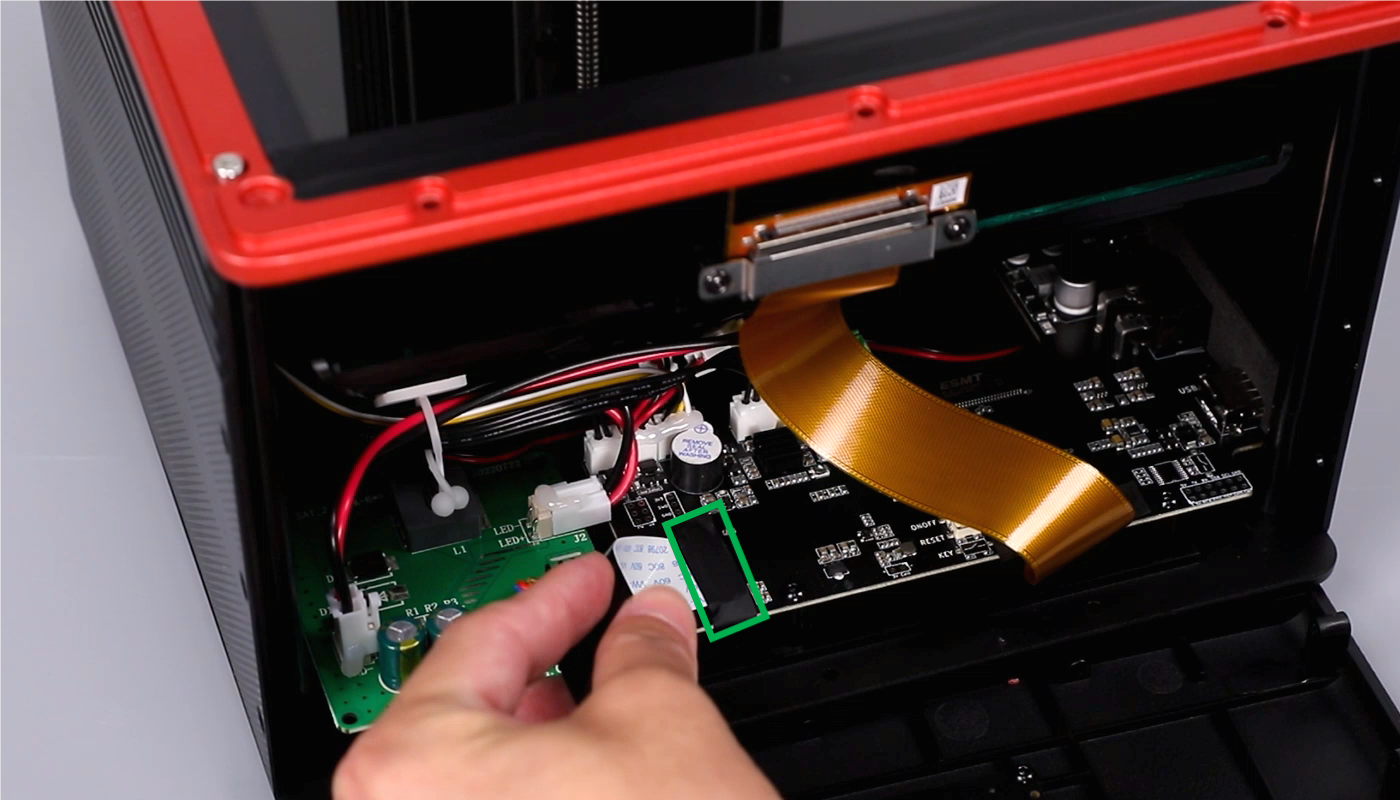
- Using a 2.0mm Allen key, loosen the two screws securing the cable clip. Remove the cable clip.
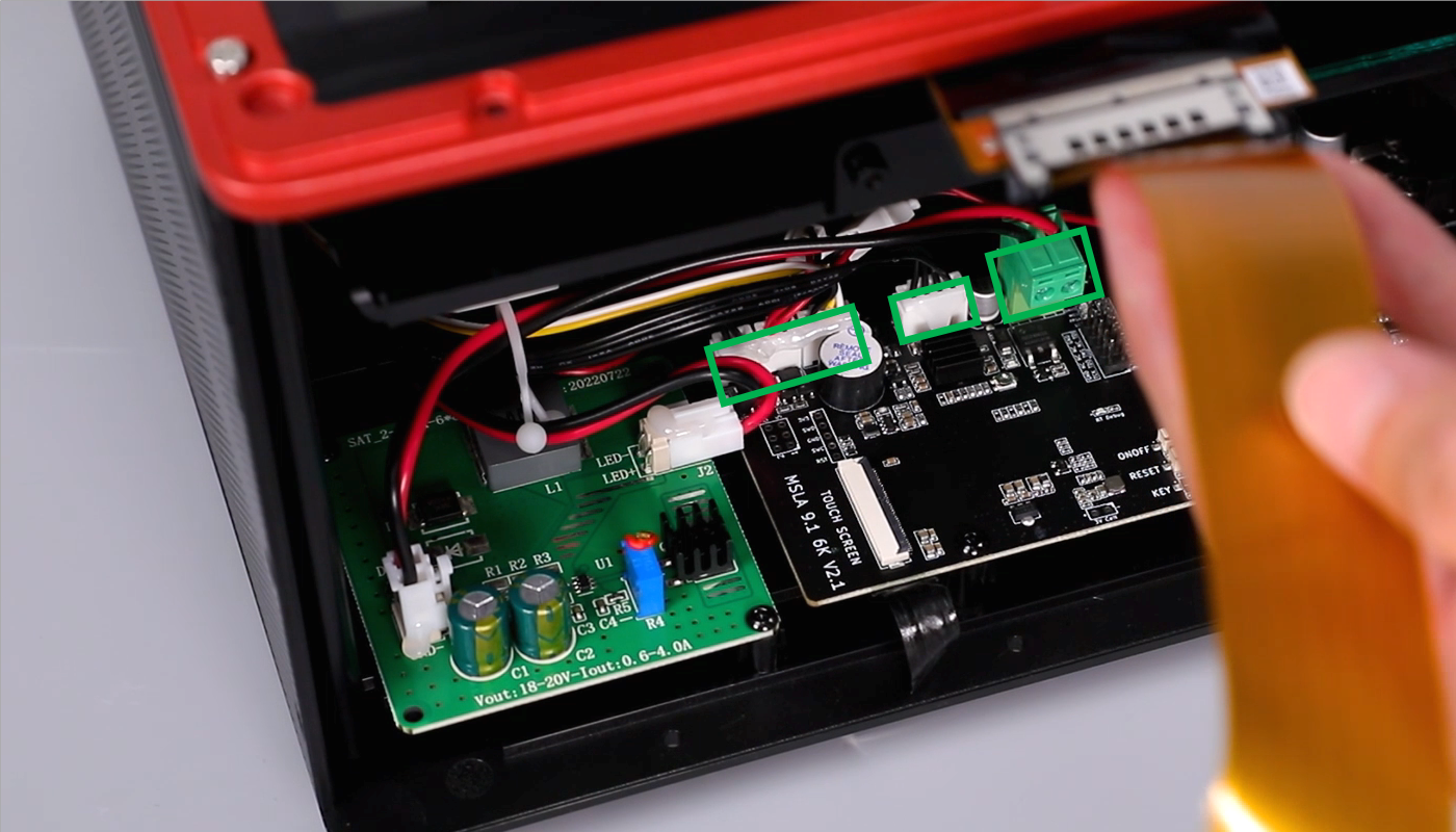
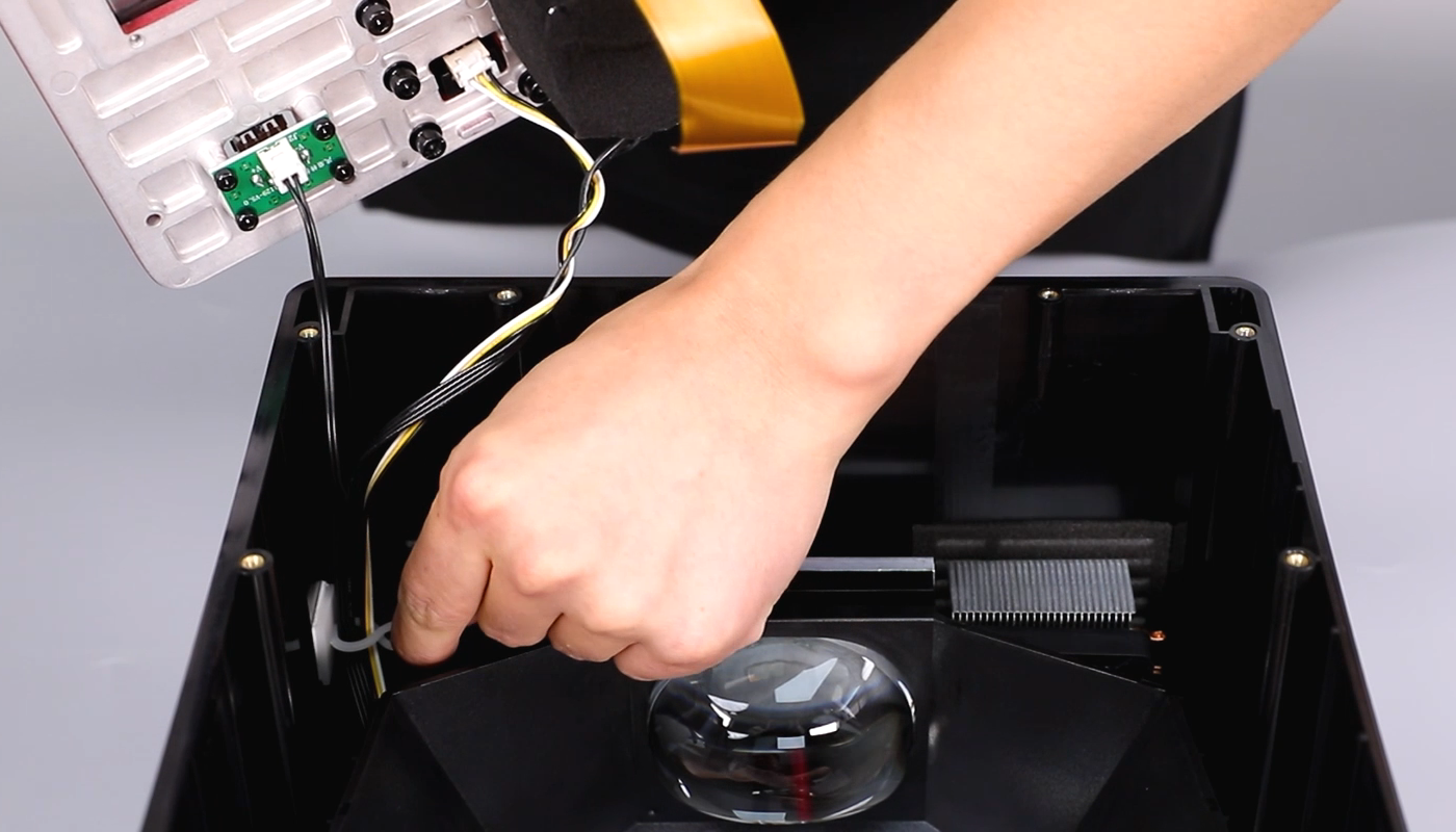
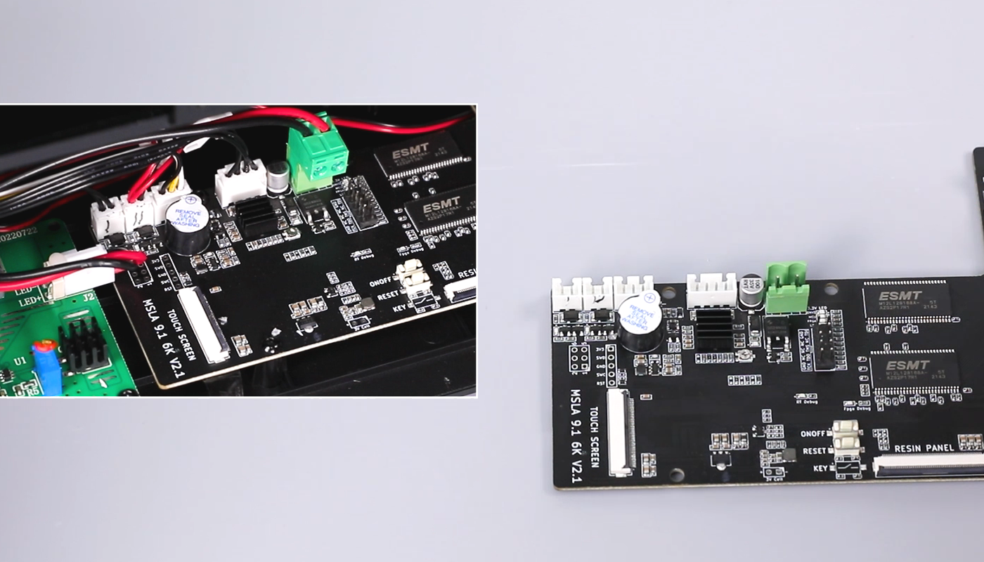
- Mark the connector of the connection cable of the motherboard (photos can be taken for reference) to facilitate subsequent installation and prevent plugging into the wrong ports. Remove sequentially the limit switch cable, the two USB connector cables, the motor ribbon cable, and the adapter cable from the motherboard to the constant current board.
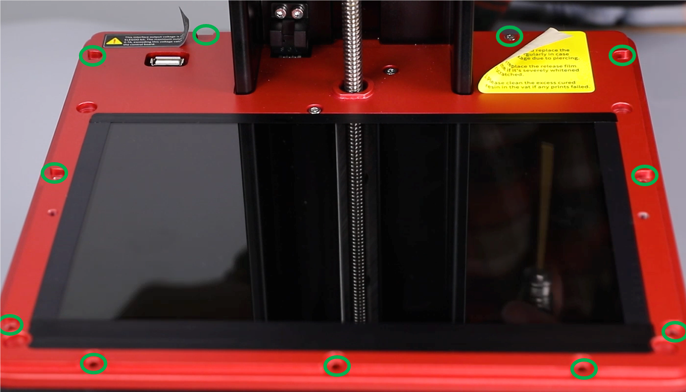
- Using a 2.5 mm Allen key, remove the eight screws securing the middle housing. Remove the middle housing. Remove the cable clip. Pull the cable with caution. Do not break the cables.
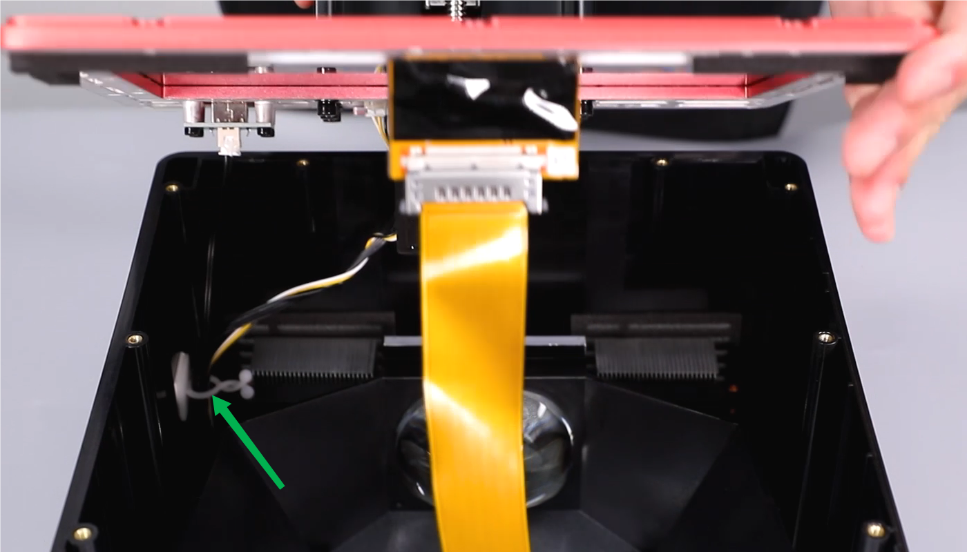
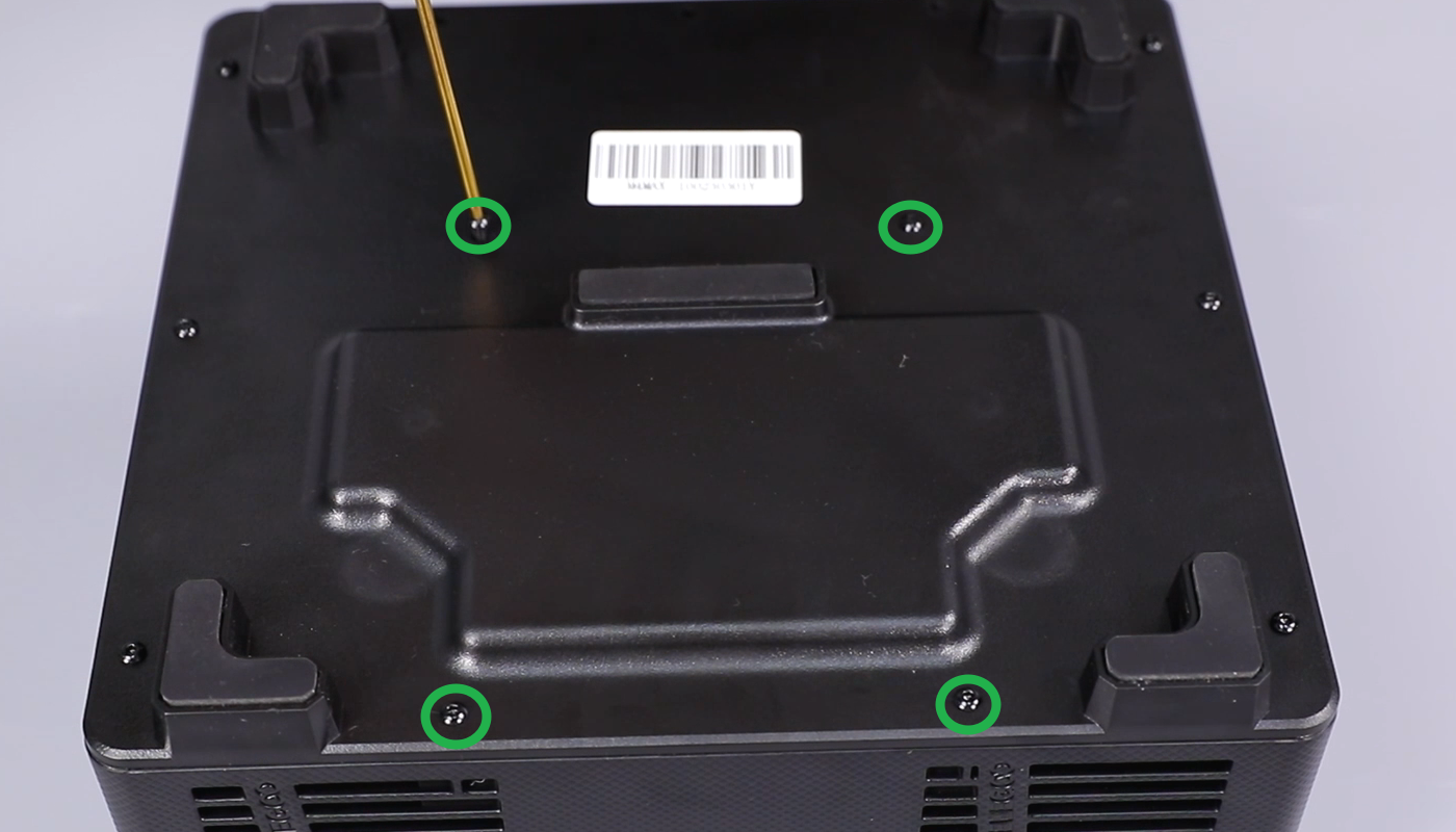
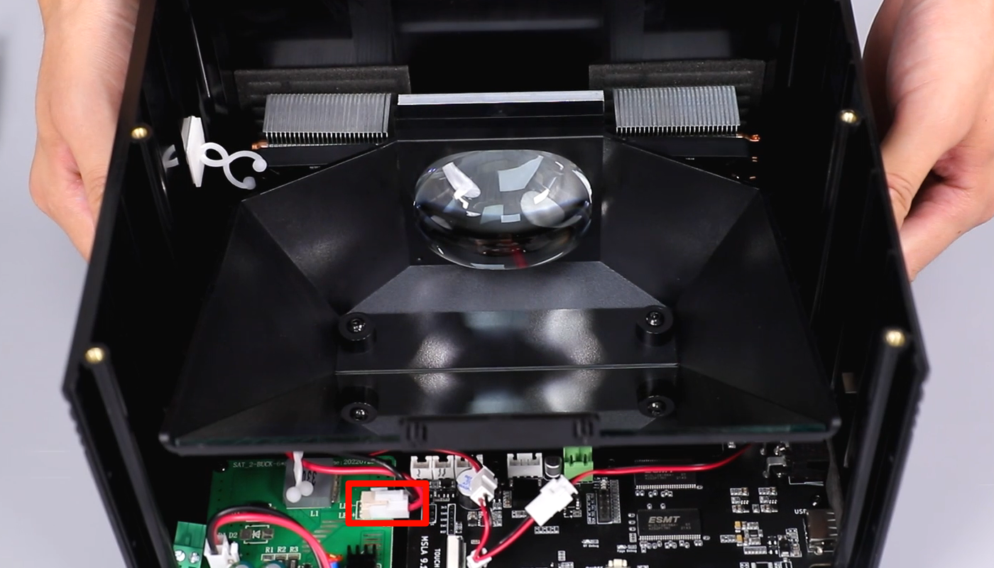
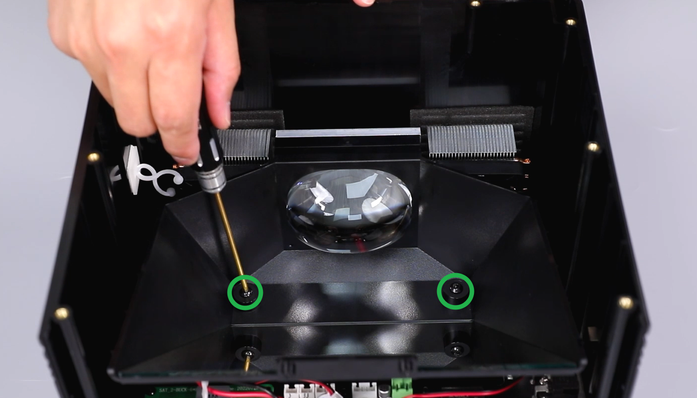
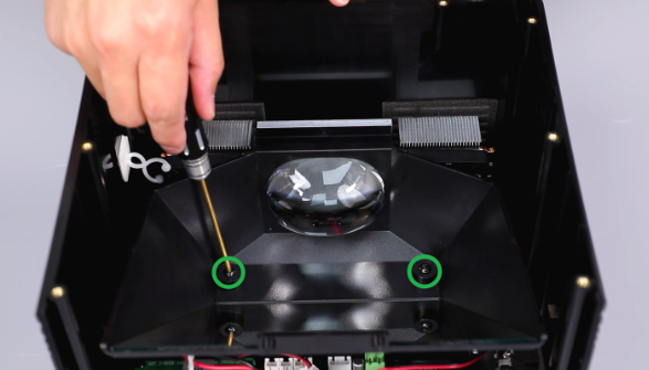
- Loosen the four screws securing the bottom cover of the printer using a 2.0 mm Allen key. Disconnect the connection cable of the UV light. Loosen the two screws securing the UV light using a 2.0 mm Allen key.
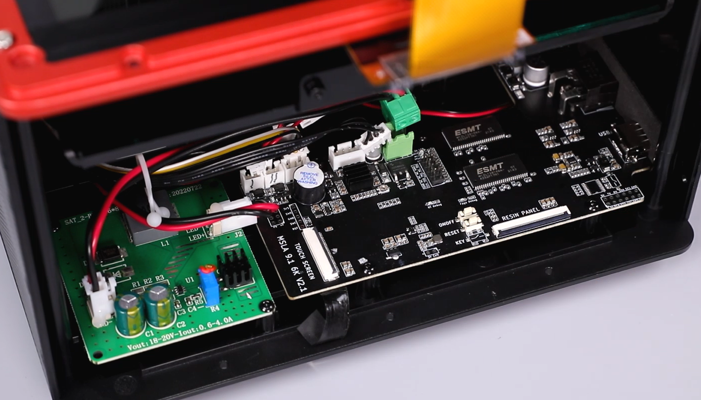
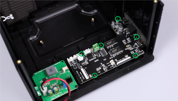
- Using a 2.0 mm Allen key, loosen the six screws securing the motherboard. Remove the old motherboard.
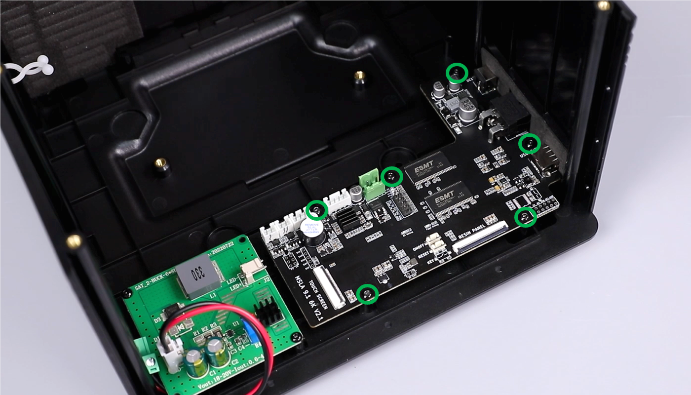
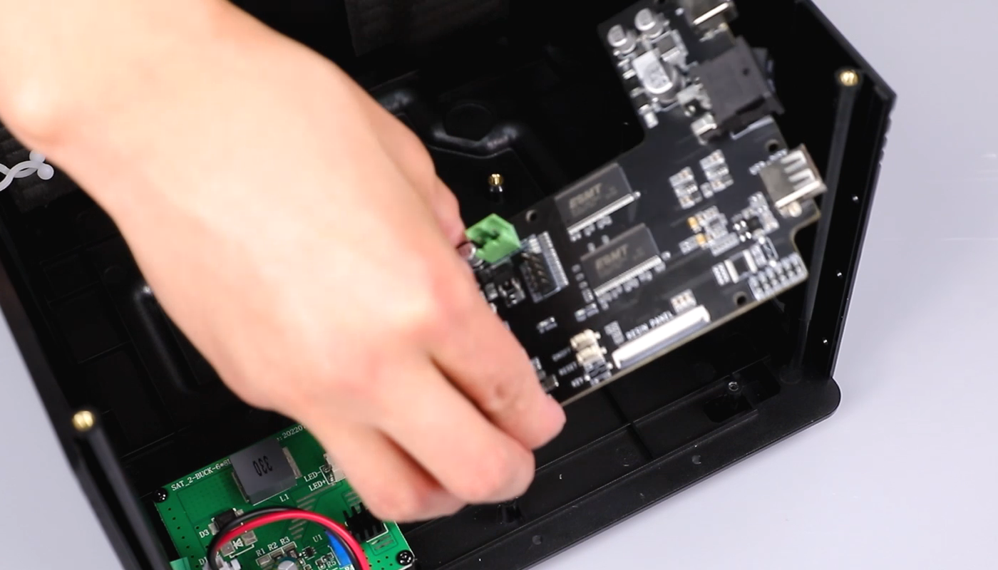
- Prepare the new motherboard and make the same markers as those on the old motherboard. Put it in the installation position. Using a 2.0 mm Allen key secure the screws.

- Put the UV light in the installation position. Using a 2.0 mm Allen key, tighten the two screws inside the printer and the four screws securing the bottom cover.


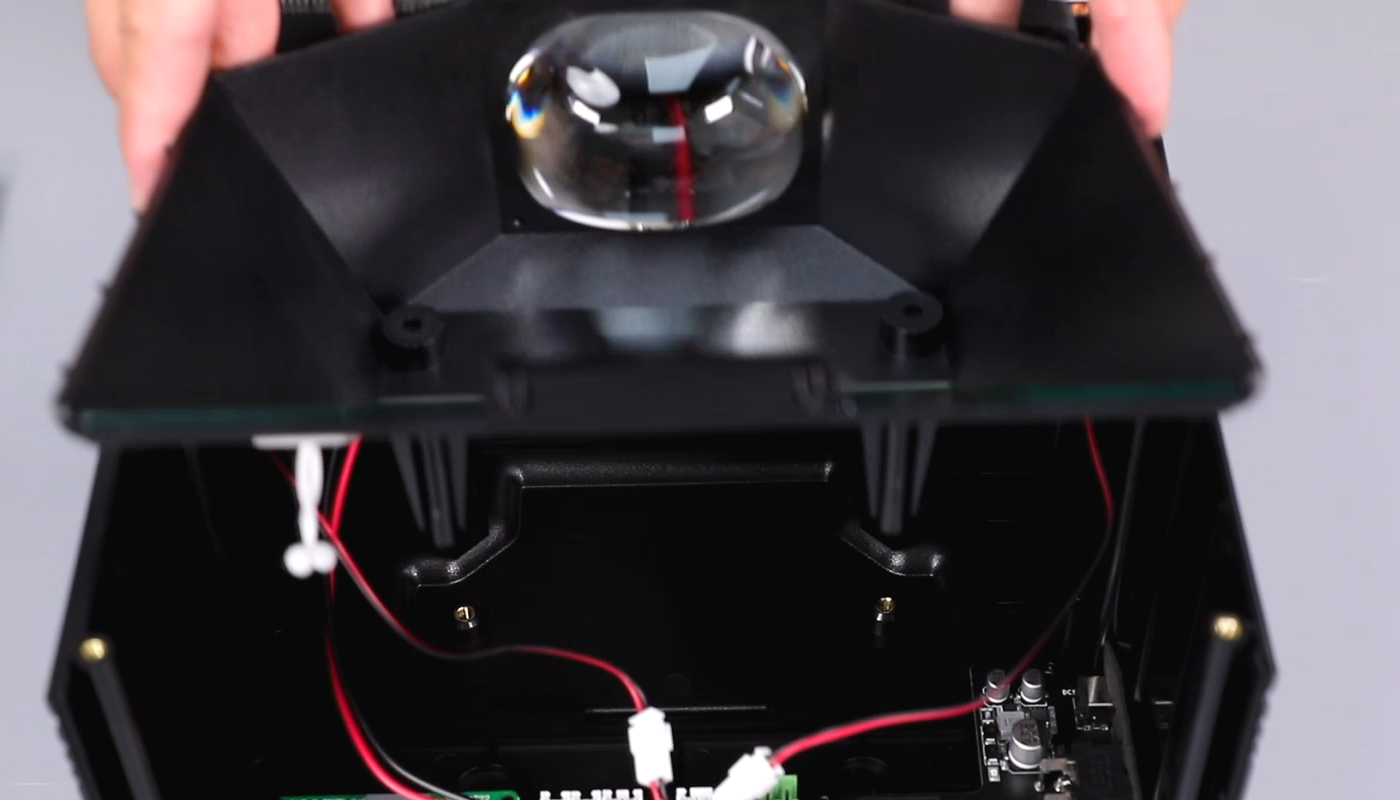
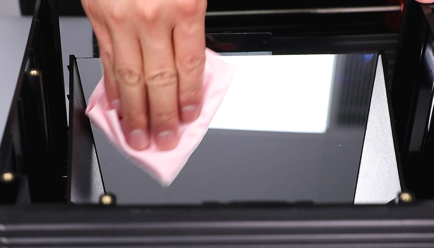
- Wipe the reflective mirror surface with a lint-free cloth to prevent fingerprints and dirt. Organize the cables and secure them with a cable clip. Install the printer's middle housing onto the printer base.

- According to the markers, connect sequentially the limit switch cable, the two USB connector cables, the motor ribbon cable, and the adapter cable from the motherboard to the constant current board.

- Install the cable clip. Using a 2.5mm Allen key, tighten the two screws securing the cable clip.
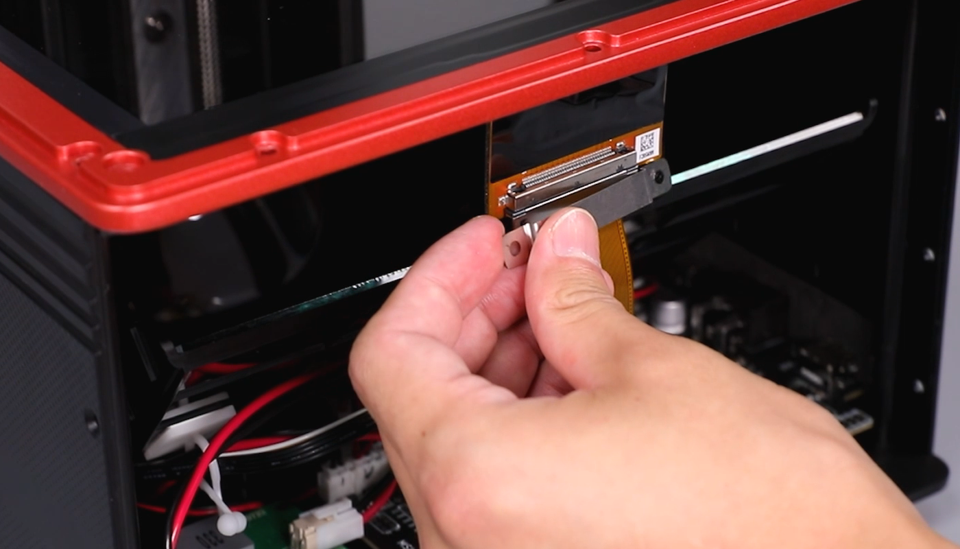

- Lift the LCD ribbon cable cover. Connect the LCD ribbon cable and close the cover. Secure the black tape. Lift the LCD ribbon cable cover. Connect the touchscreen ribbon cable and close the cover. Adhere the black tape.
Ribbon cables of the LCD screen

Ribbon cables of the touchscreen

- Install the front cover of the touchscreen. Using a 2.5 mm Allen key, tighten the eleven screws securing the middle housing of the printer.
- Using a 2.0 mm Allen key, tighten the three screws securing the left part of the front cover of the printer base. Using a 2.0mm Allen key, secure the three screws securing the right side of the front cover of the printer base.

- Using a 2.0 mm Allen key, tighten the three screws securing the lower part of the printer base.
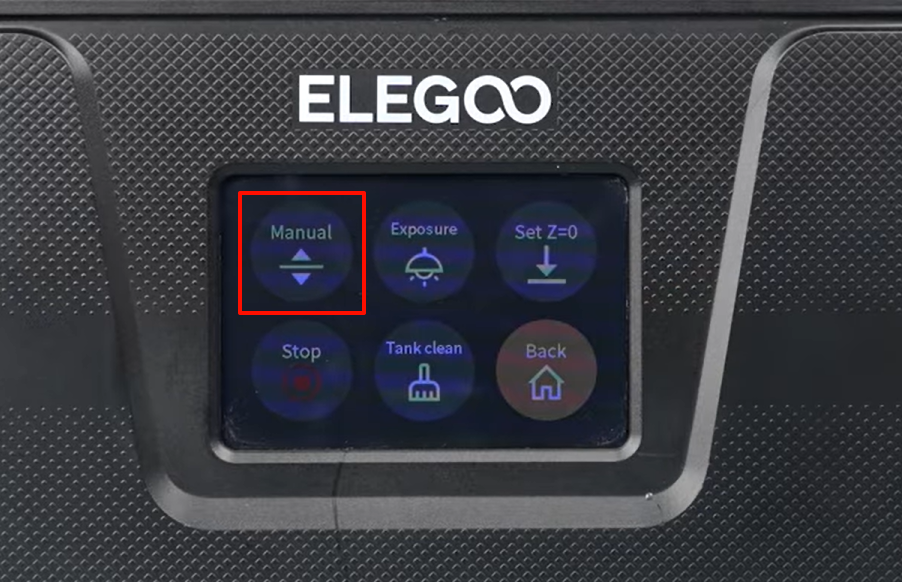
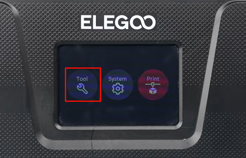
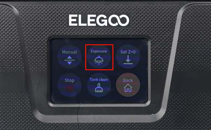
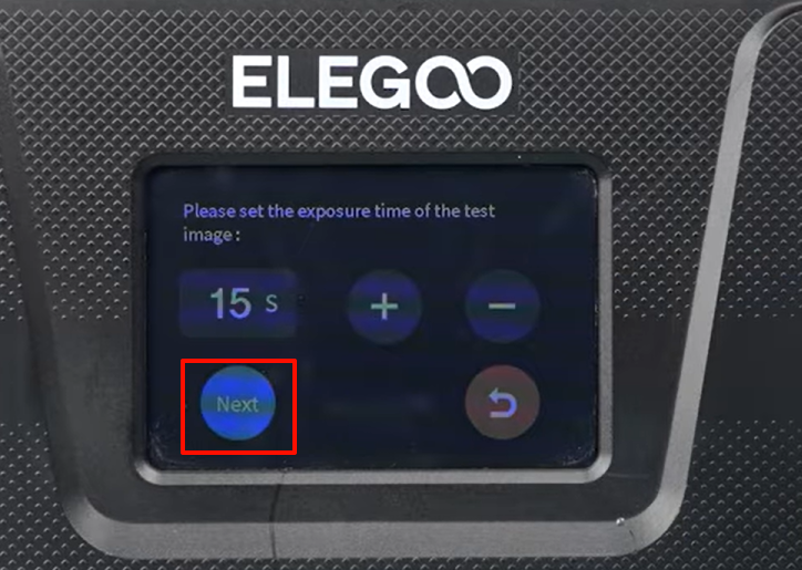
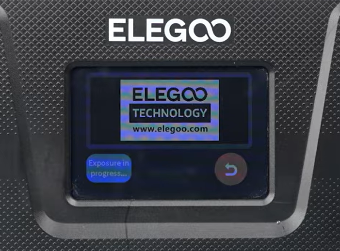
- Power on the printer. On the touchscreen, select Tool - Exposure - Next. The screen shows the correct exposure logo.
- Select Tool - Manual on the touchscreen. Press Home button. The printer is ready for use after the printer operates the homing process normally.