¶ Tools and Materials
- 2.5mm Allen key x 1
- 2.0mm Allen key x 1
- Marker pen x 1
- A pair of pliers
- Dust-free cloth
- A pair of Gloves
- Plastic scraper x1
¶ Tutorial Video
Coming soon.
¶ Instruction
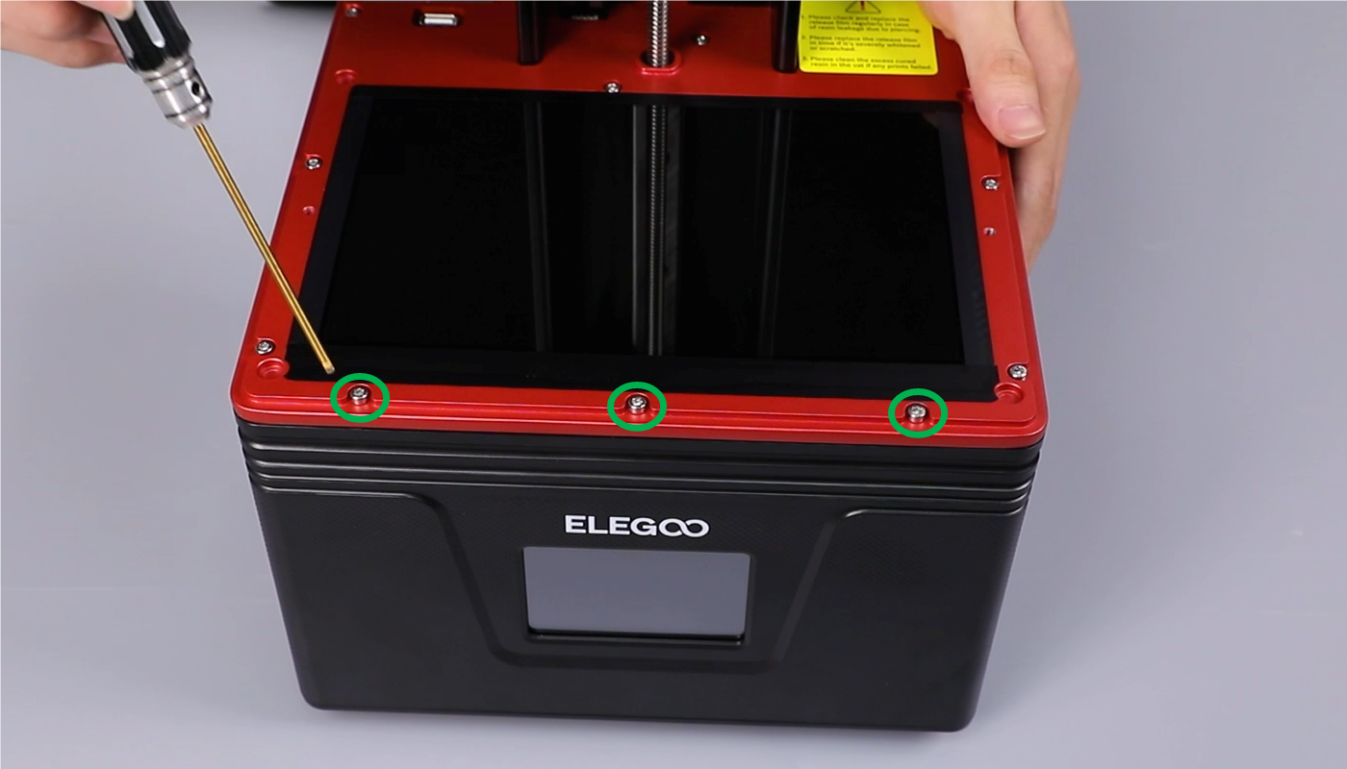
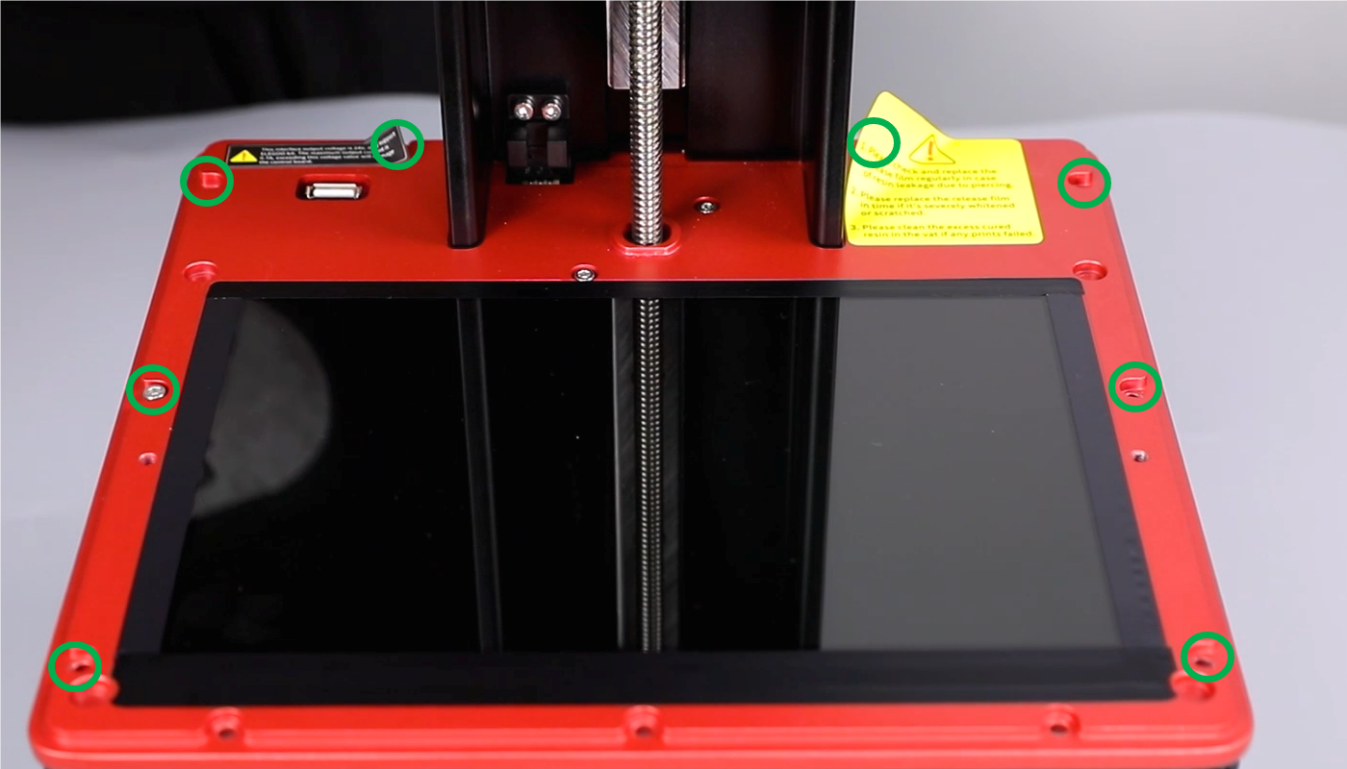
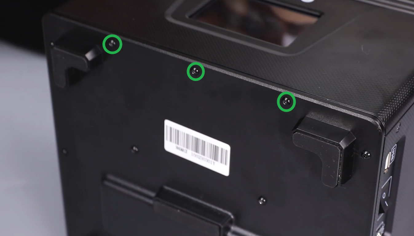
- Using a 2.5 mm Allen key, loosen the three screws securing the upper part of the front cover of the printer base.
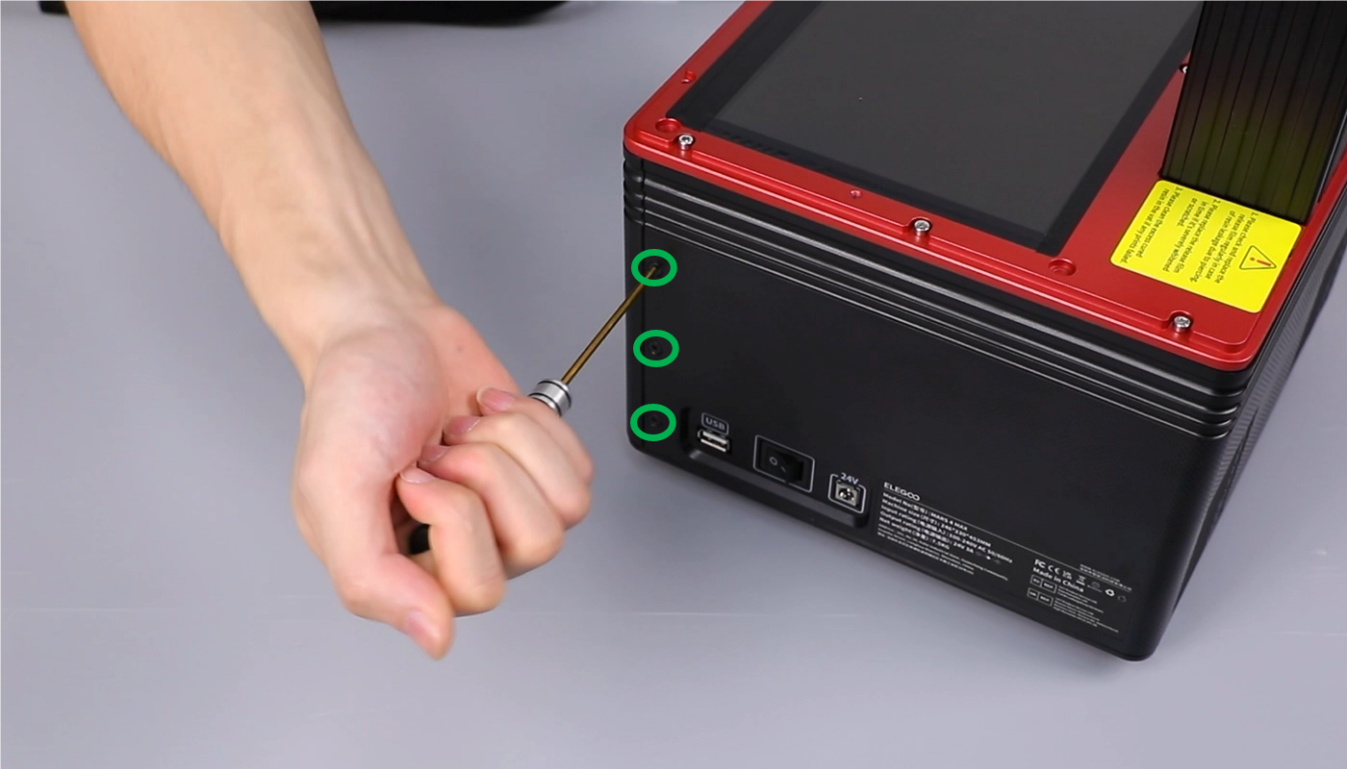
- Using a 2.0 mm Allen key, loosen the three screws securing the left part of the front cover of the printer base.
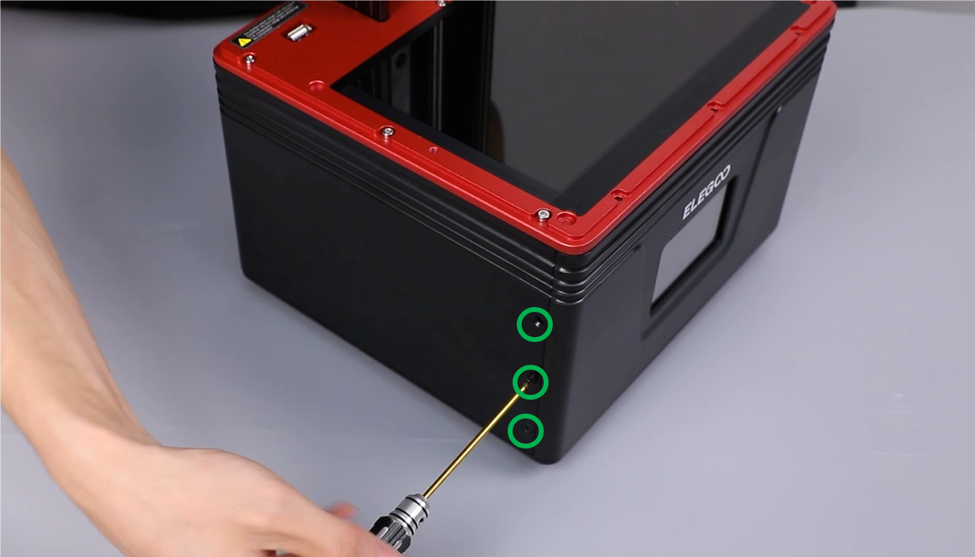
- Using a 2.0 mm Allen key, loosen the three screws securing the right part of the front cover of the printer base.
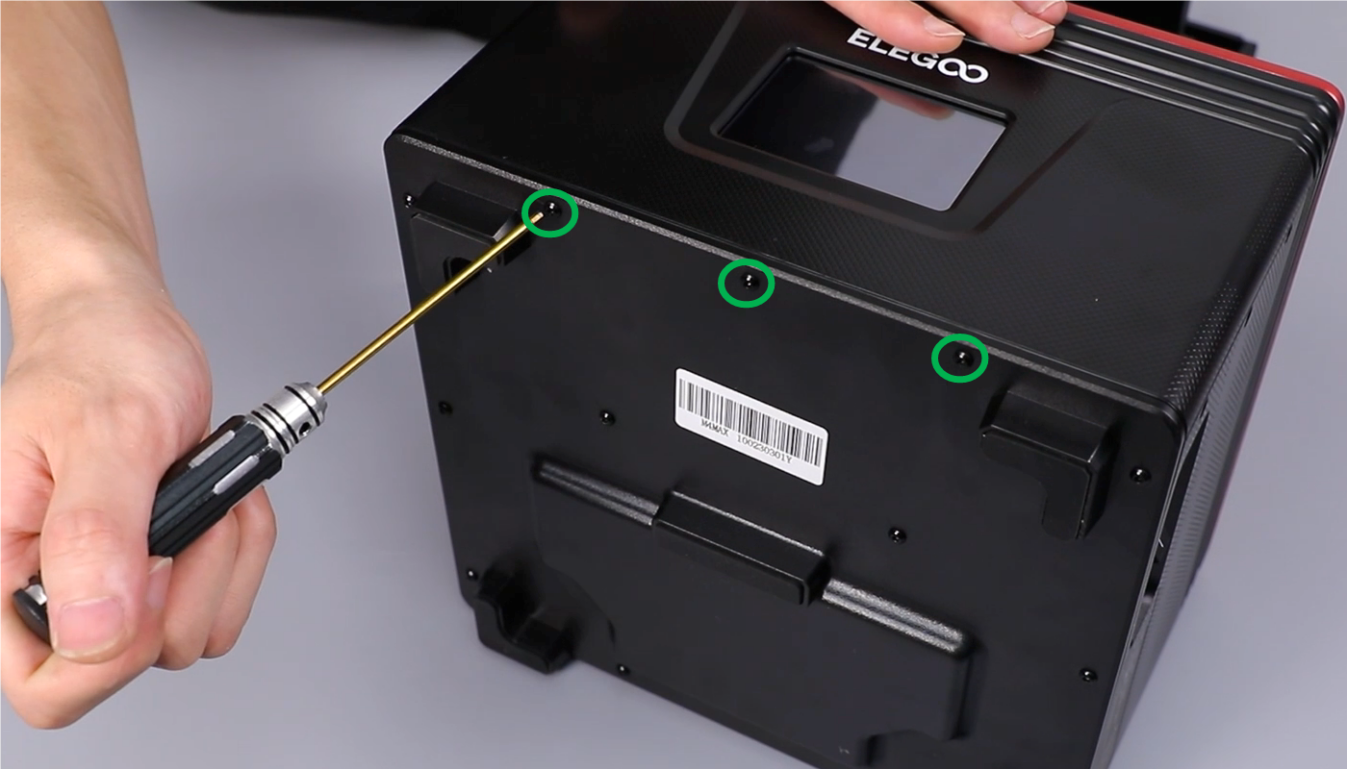
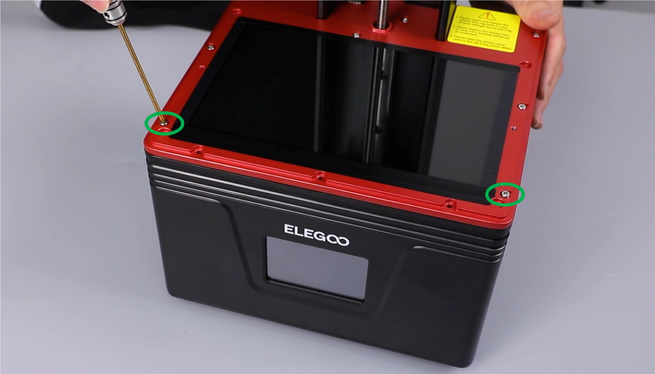
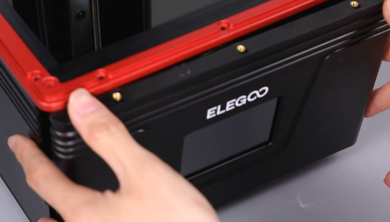
- Using a 2.0 mm Allen key, remove the three screws securing the lower part of the base front cover. Using a 2.5mm Allen key, loosen the two screws at the right and left side of the red middle housing. Remove the touchscreen and lay it flat on the table.
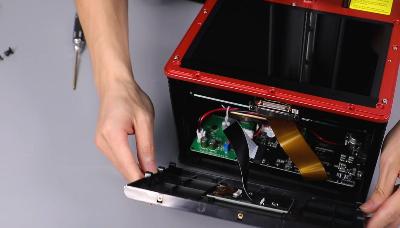
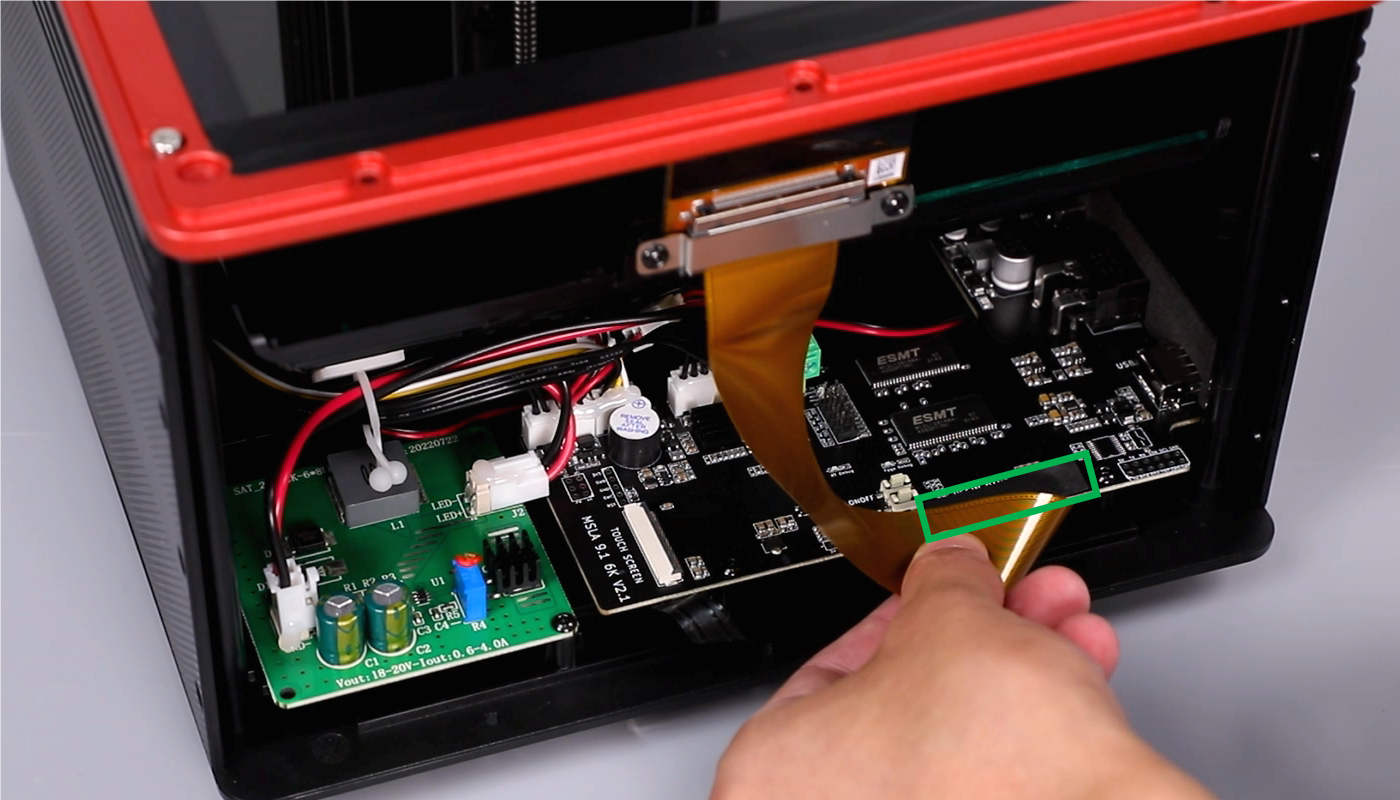
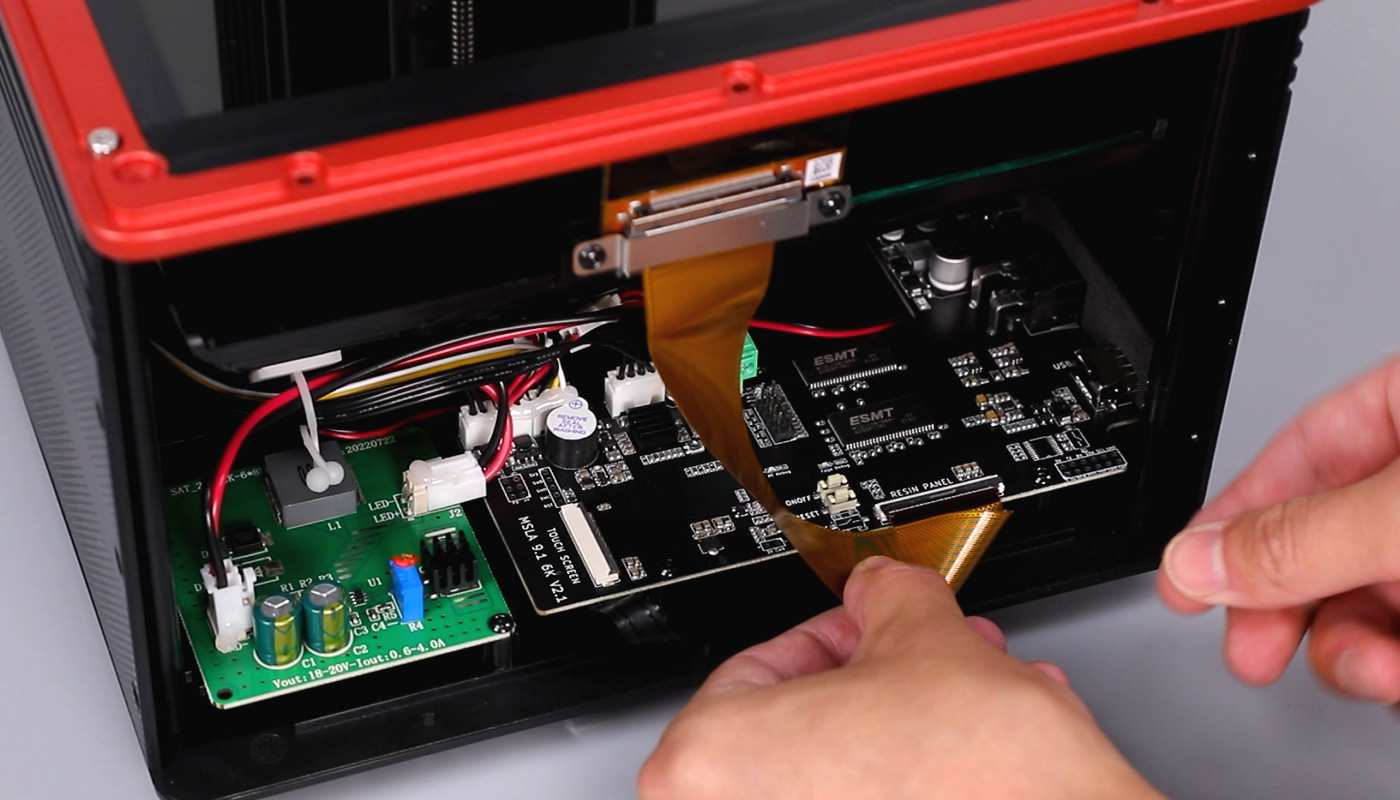
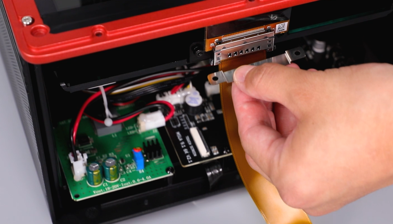
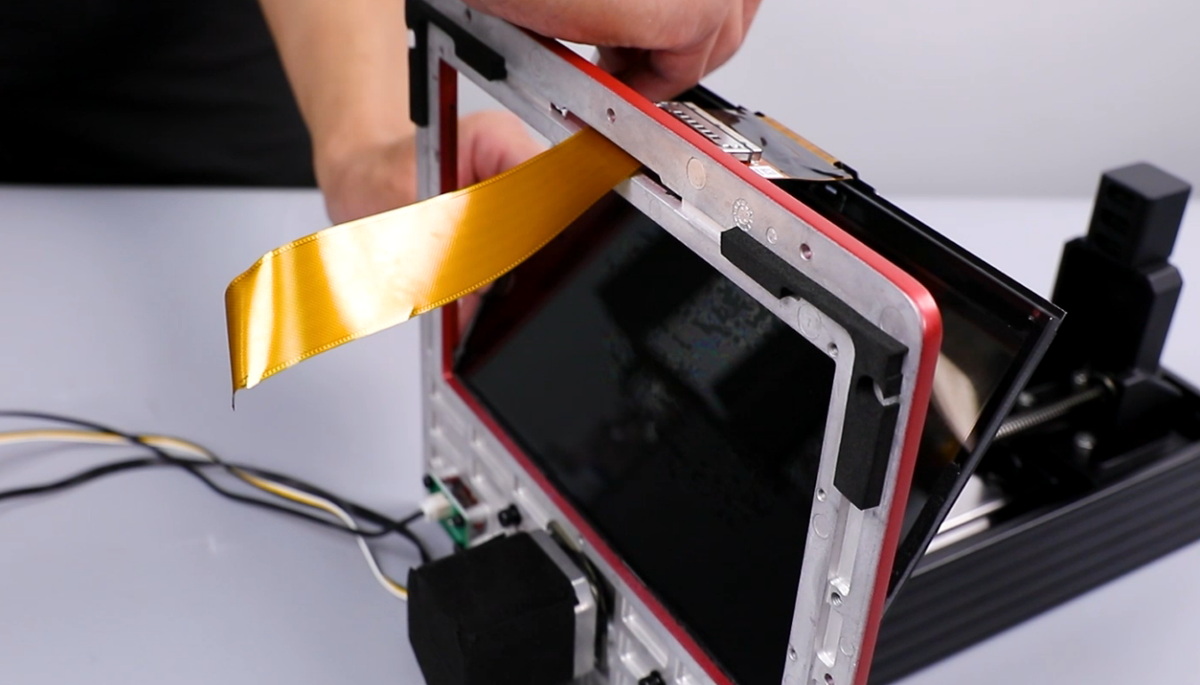
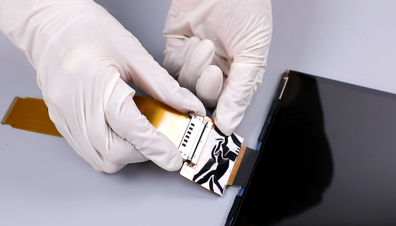
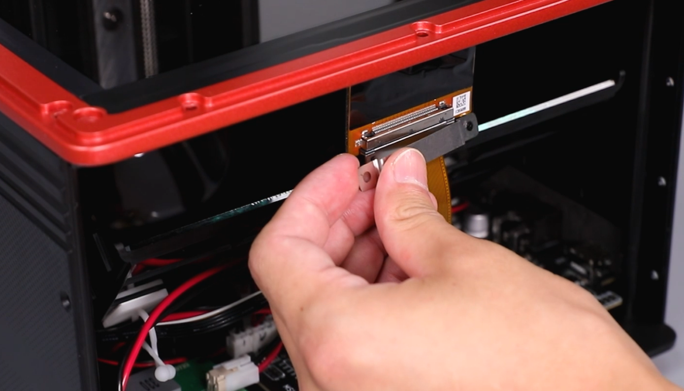
- Peel off the tape securing the ribbon cables of the LCD screen and the touchscreen. Lift the covers securing the bases of the LCD screen and the touchscreen. Remove the ribbon cables of the LCD screen and the touchscreen.
Ribbon cable of the touchscreen
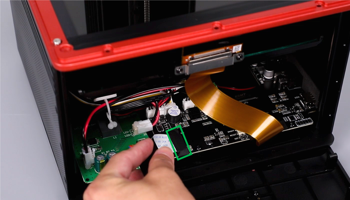

Ribbon cable of the LCD screen
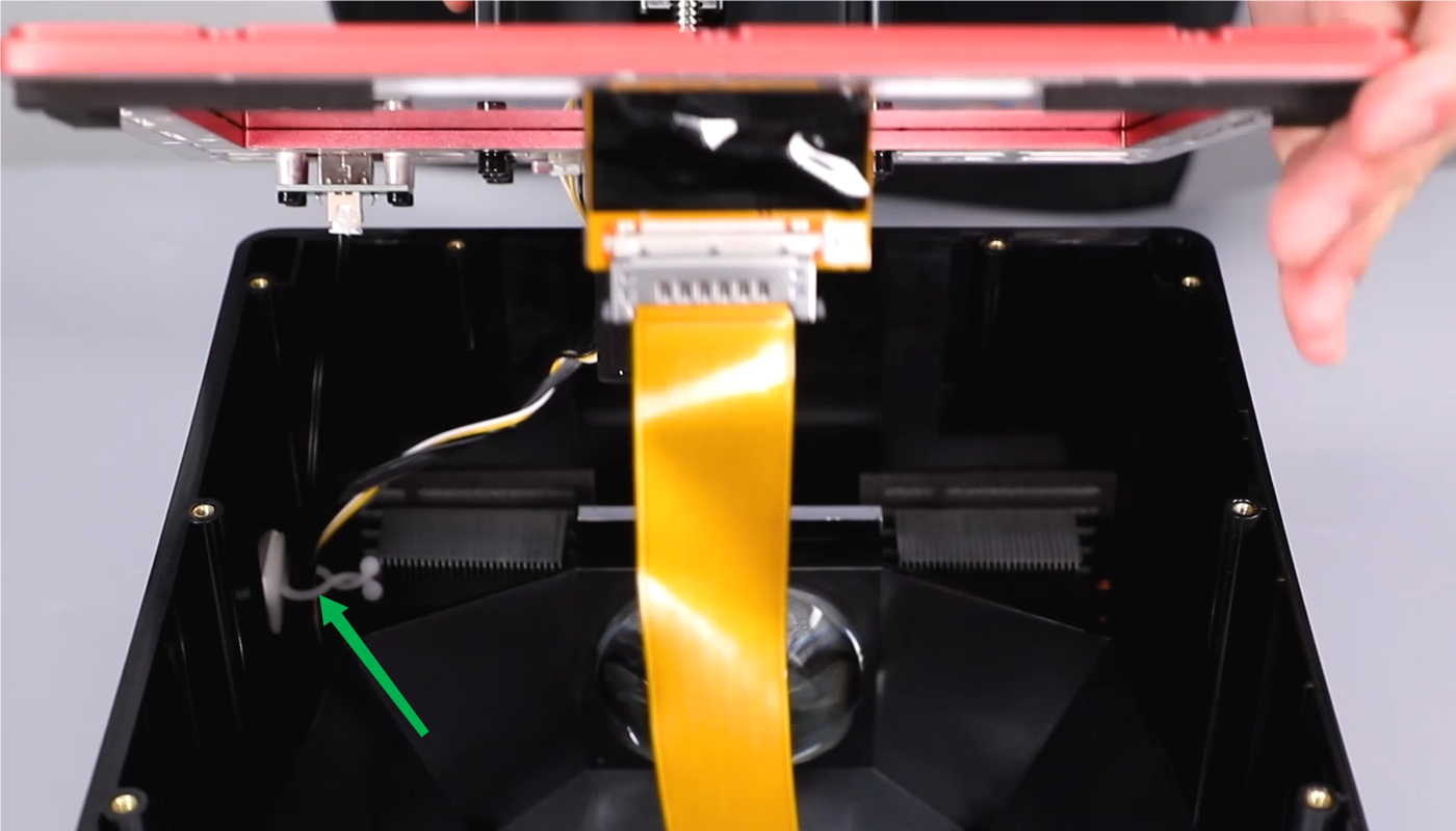
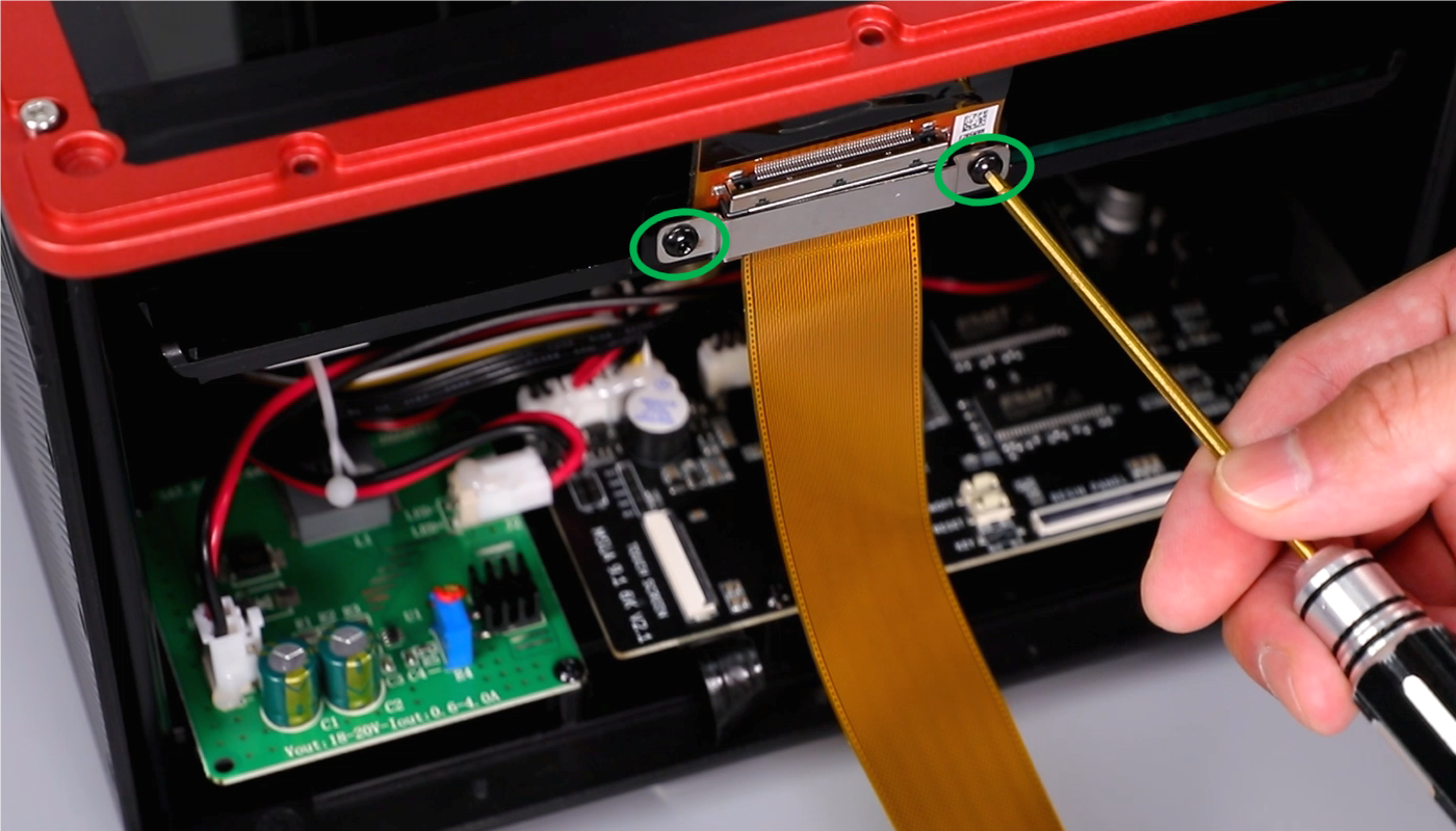
- Using a 2.0mm Allen key, loosen the two screws securing the cable clip. Remove the cable clip.

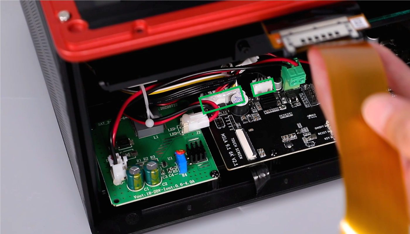
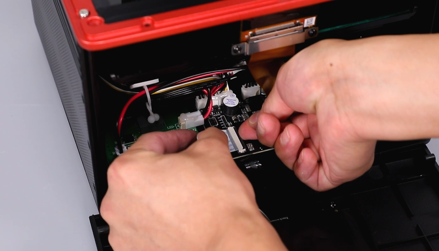
- Mark the connector of the connection cable of the motherboard (photos can be taken for reference) to facilitate subsequent installation and prevent plugging into the wrong ports. Remove sequentially the limit switch cable, the USB connector, the connection cable of the cooling fan, and the motor cables.
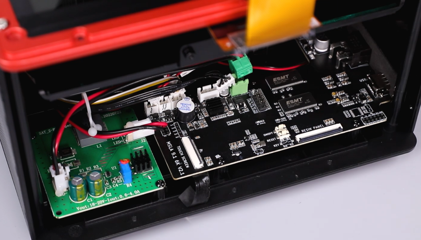
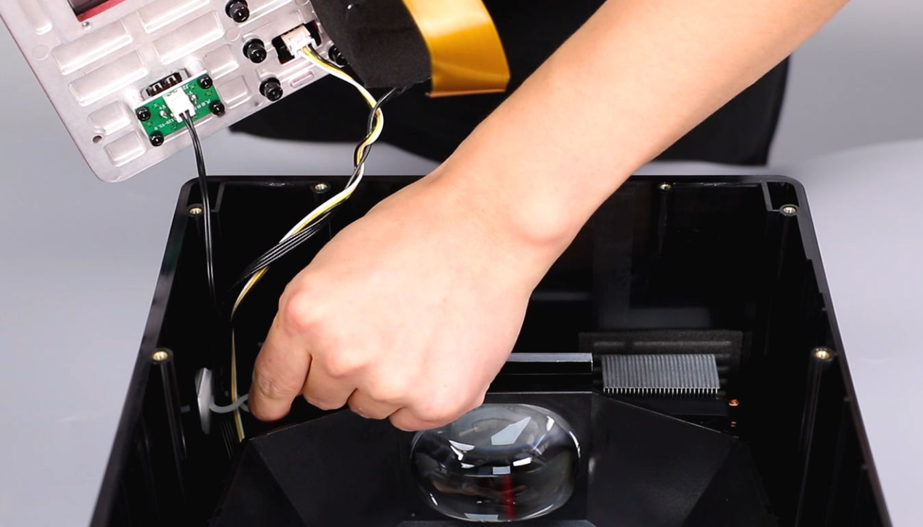
- Using a 2.5 mm Allen key, remove the eight screws securing the middle housing. (One of the screws is located under the label.) Remove the middle housing. Remove the cable clip. Pull the cable with caution. Do not break the cables.
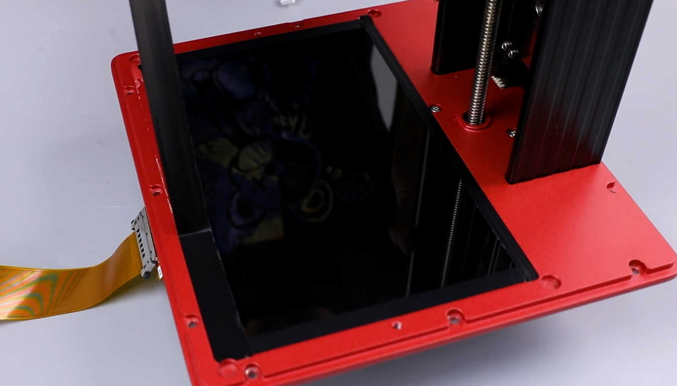
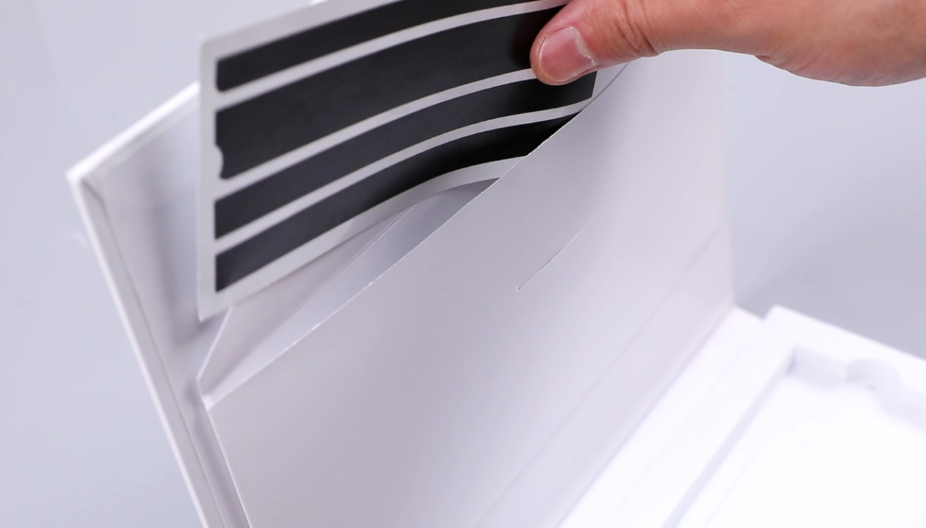
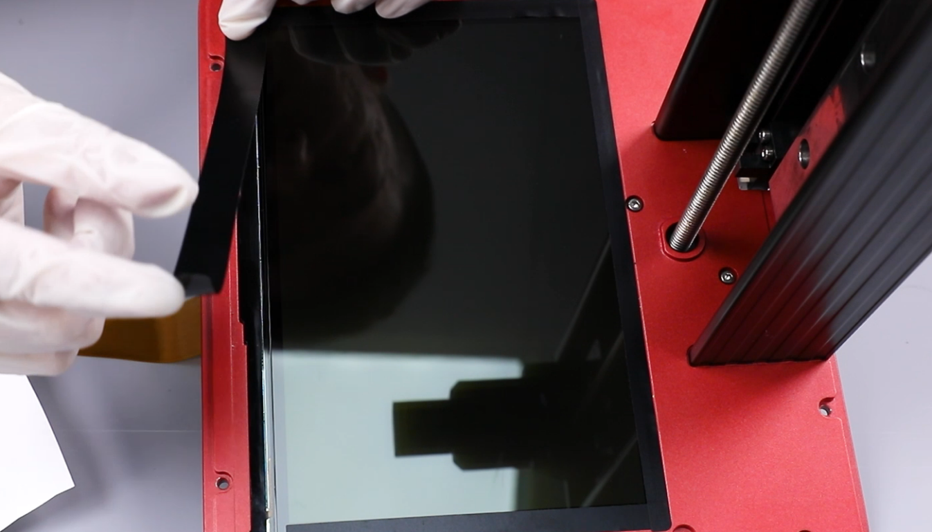
- Remove the tape securing the LCD screen. Detach the LCD screen from the middle housing.
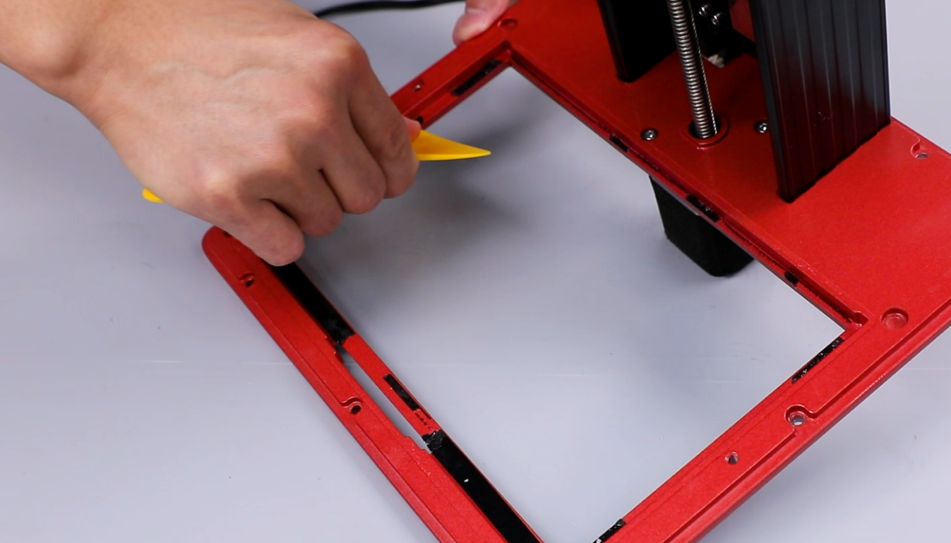
NOTE: If the tape is sticky, clean it using alcohol and plastic scraper.
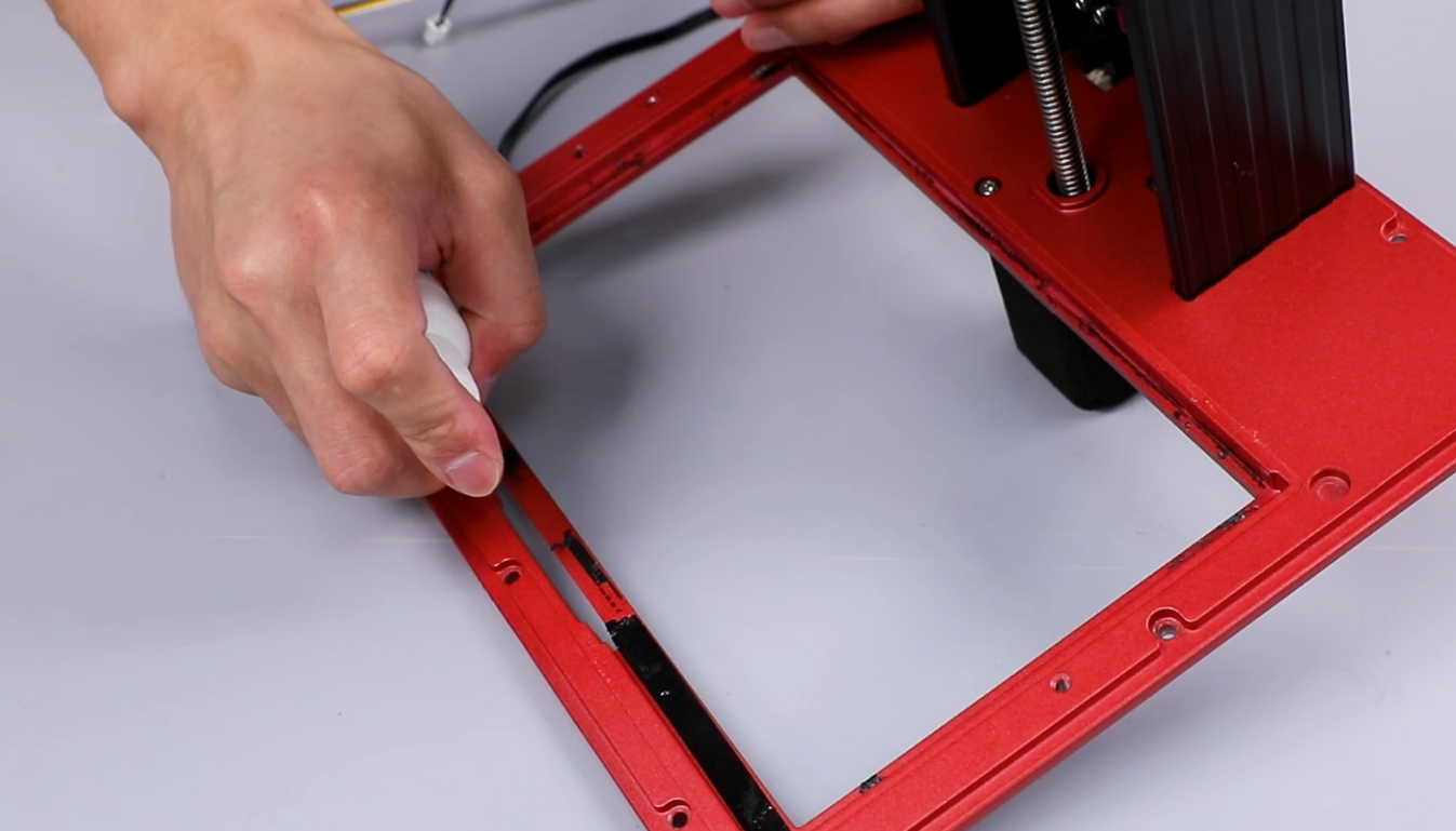
- Clean the excess tape from the middle housing to facilitate the subsequent installation of new tape.
(NOTE: If the tape is sticky, clean it using alcohol and plastic scraper.)
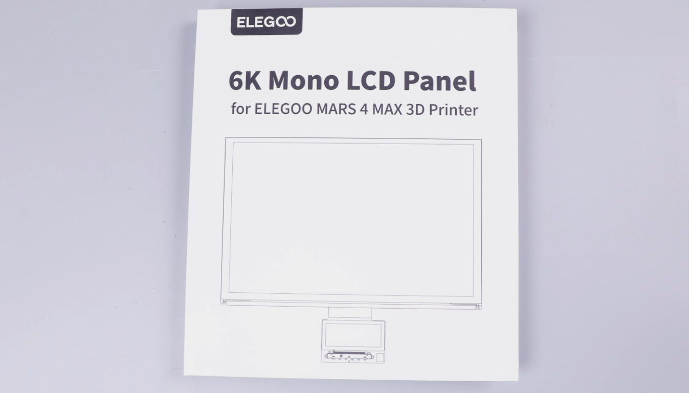
- Prepare the new LCD screen, screen cables and tape.
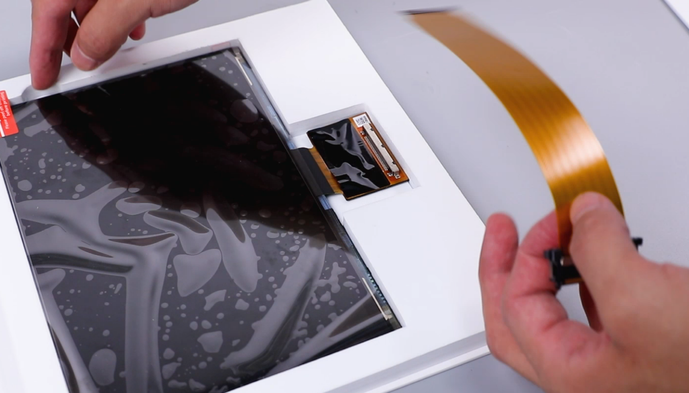
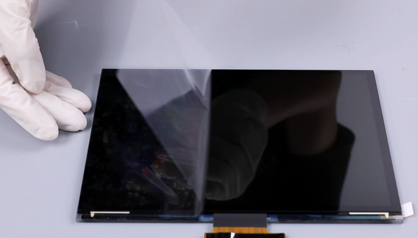
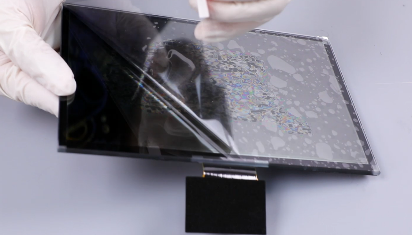
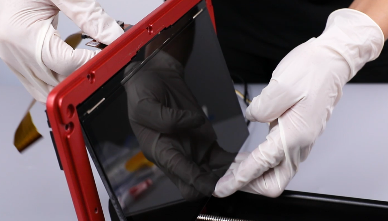
- Peel off the protective cover of the screen. Connect the cables to the PCB of the screen.
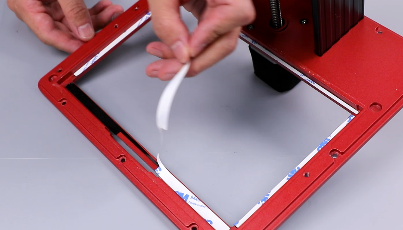
- Install the screen to the middle housing and adhere the tape. Align the tape with the groove.
(NOTE: Take off the gloves when you adhere the tape.)
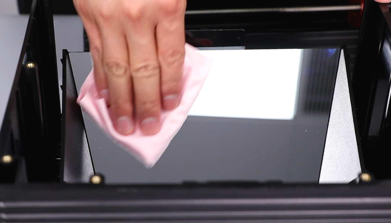
- Wipe the reflective mirror surface with a lint-free cloth to prevent fingerprints and dirt. Organize the cables and secure them with a cable clip. Install the printer's middle housing onto the printer base.

- According to the markers, connect sequentially the limit switch cable, the USB connector, the connection cable of the cooling fan, and the motor cables.

- Install the cable clip. Using a 2.0mm Allen key, tighten the two screws securing the cable clip.
- Lift the LCD ribbon cable cover. Connect the LCD ribbon cable and close the cover. Secure the black tape. Lift the LCD ribbon cable cover. Connect the touchscreen ribbon cable and close the cover. Adhere the black tape.
Ribbon cable of the LCD screen


Ribbon cable of the touchscreen

- Install the front cover of the touchscreen. Using a 2.5 mm Allen key, tighten the eleven screws securing the middle housing of the printer.
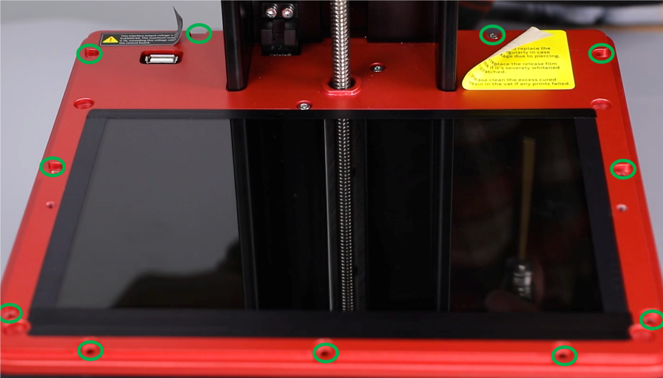
- Using a 2.0 mm Allen key, tighten the three screws securing the left part of the front cover of the printer base. Using a 2.0mm Allen key, secure the three screws securing the right side of the front cover of the printer base.


- Using a 2.0 mm Allen key, tighten the three screws securing the lower part of the printer base.
- Power on the printer. On the touchscreen, select Tool - Caliberate - Next. The screen shows the correct exposure logo and the printer is ready for use.