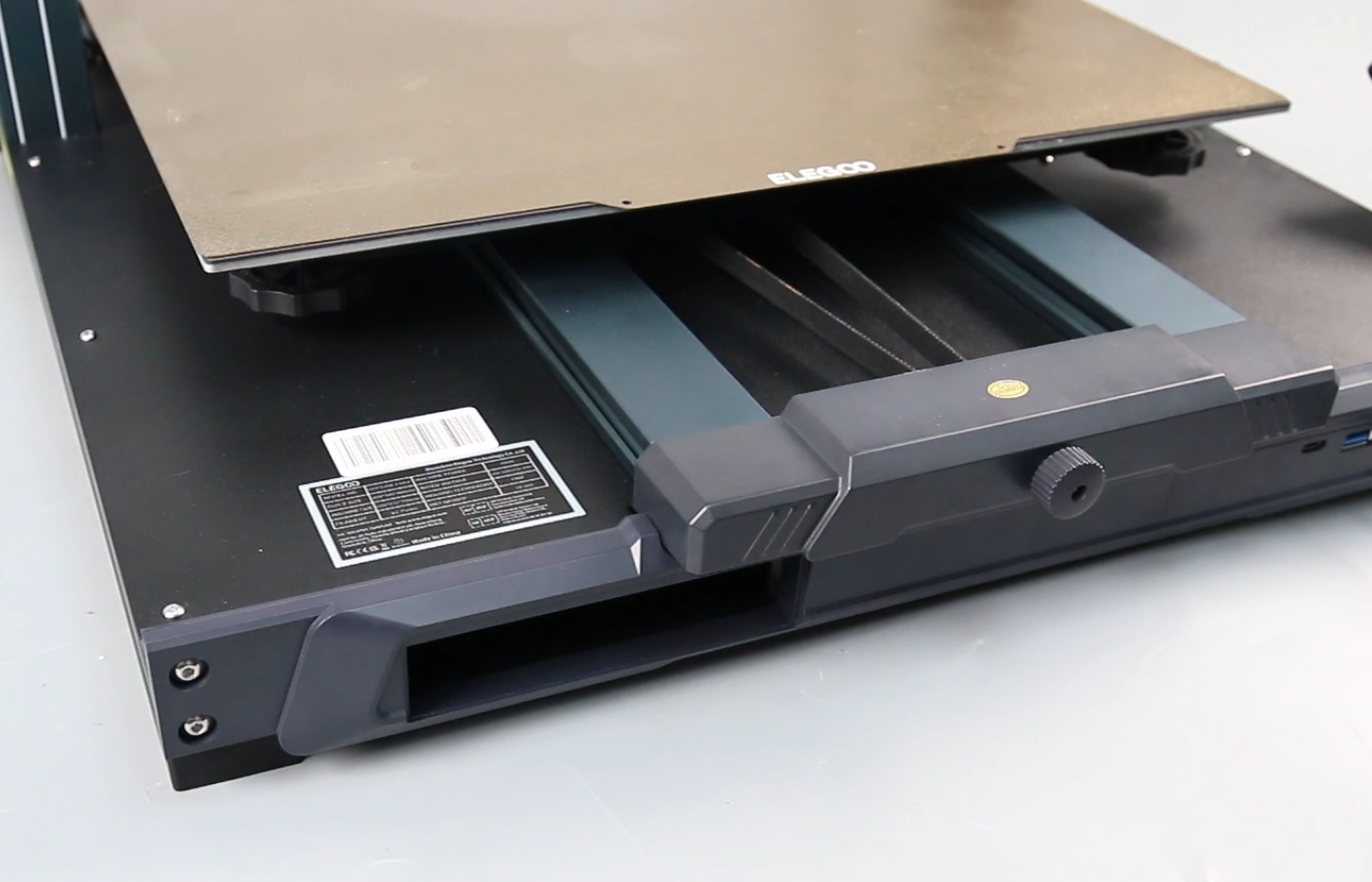
Y-axis Acceleration Sensor Cable Replacement
Tools and materials needed
●2.0mm Allen wrench
●3.0mm Allen wrench
●Philips screwdriver
●Diagonal pliers
Reference video
Precautions before operation and machine status
This operation involves the disassembly and installation of the internal wiring of the printer. Please take all necessary precautions before disassembling the printer. Turn off the machine and cut off the power supply.
Operation steps
1. Pull out the drawer box from the front of the printer (The Neptune 4 Plus model does not have a drawer box, so you can skip this step).

2. Use a 2.0mm Allen wrench to loosen the 20 screws fixed on the bottom cover of the printer.

3. Slowly take out the bottom cover and unplug the cable port of the motherboard cooling fan.

4. Use diagonal pliers to cut the four cable ties fixing the cables inside the printer.

5. Unplug the hotbed thermistor and Y-axis acceleration sensor cables from the motherboard.

6. Use diagonal pliers to cut the cable tie fixing the hot bed cable.

7. Use a Phillips screwdriver to loosen the two fixing screws on the heating port of the hot bed and remove the two hot bed cables.

8. Loosen the hand-twist nut of the Y-axis belt tensioner.

9. Use a 2.0mm Allen wrench to loosen the two fixing screws on the Y-axis rear baffle behind the hot bed, use a 3.0mm Allen wrench to loosen the two screws fixed on the side of the Y-axis rear baffle, and remove the Y-axis rear baffle.


10. Slide the hot bed and remove the whole hot bed from the rear of the printer (Be careful to comb the belt in the process of sliding the heated bed).


11. Use a 2.0mm Allen wrench to loosen the two screws fixing the Y-axis acceleration sensor.

12. Use diagonal pliers to cut off the two cable ties fixing the hot bed cable.

13. Remove the PEI platform, use a 2.0mm Allen wrench to loosen the two screws fixing the cable fastener of the hot bed, and remove the hot bed cable fastener assembly.


14. Tear off the tape wrapped around the hot bed cable (Keep the tape and you can continue to use it later).

15. Pull out all the cables connected to the hot bed from the cable holes on the printer base, and pull out all the cables from the mesh cable sleeve.

16. Take out the Y-axis acceleration sensor, remove the connected cable, and use a 2.0mm Allen wrench to tighten the two fixing screws of the Y-axis acceleration sensor (note that the cable port faces outward).

17. Insert the new Y-axis acceleration sensor cable into the port, and thread all the cables connected to the hot bed into the mesh cable sleeve.


18. Wrap black tape around the end of the mesh cable sleeve and install the hot bed cable fastener assembly.


19. Use a 2.0mm Allen wrench to tighten the two screws fixing the hot bed cable fastener.

20. Thread all the cables connected to the hot bed through the cable hole on the printer base.

21. From the rear of the Y-axis aluminum profile, slide the hot bed assembly onto the Y-axis aluminum profile, and comb the Y-axis timing belt when sliding the hot bed assembly.

22. Align the screw holes, place the driven pulley block into the Y-axis front panel, and install the hand-twist nut.


23. Hang the belt on the hot bed center tensioning wheel and the Y-axis motor synchronous wheel.


24. Turn the Y-axis belt tensioner knob to adjust the Y-axis belt tension to moderate. It should feel neither too loose nor too tight when you pinch it with your hands.


25. Install the Y-axis rear baffle, use a 2.0mm Allen wrench to tighten the two screws fixed on the top of the Y-axis rear baffle, and use a 3.0mm Allen wrench to tighten the two screws fixed on the side of the Y-axis rear baffle.

26. According to the "red positive and black negative" principle, insert the hot bed cable into the port, use a Phillips screwdriver to tighten the two fixing screws of the heating port of the hot bed, and cover it with a brown plastic protective cover.

27. Insert the Y-axis acceleration sensor cable and the hot bed thermistor cable into the motherboard port.


28. Use two cable ties to fix the hot bed cable to the hot bed cable fastener, and subtract the excess part.

29. Slide the heated bed to the very front, and ensure that the heated bed cable is long enough for the heated bed movement. Use five cable ties to fix the internal cables of the printer and subtract the excess.


30. Place the bottom cover in the mounting position, insert the motherboard cooling fan cable into the motherboard port, and use a 2.0mm Allen wrench to tighten the 20 screws fixed on the bottom cover of the printer.


31. Reinstall the drawer box in front of the printer, turn on the printer, and click [Settings-Advanced Settings-Input Shaping-Y-Axis-Start Detection] on the touch screen. After the Y-axis vibration detection is normal, re-level the printer and you can use it normally.


