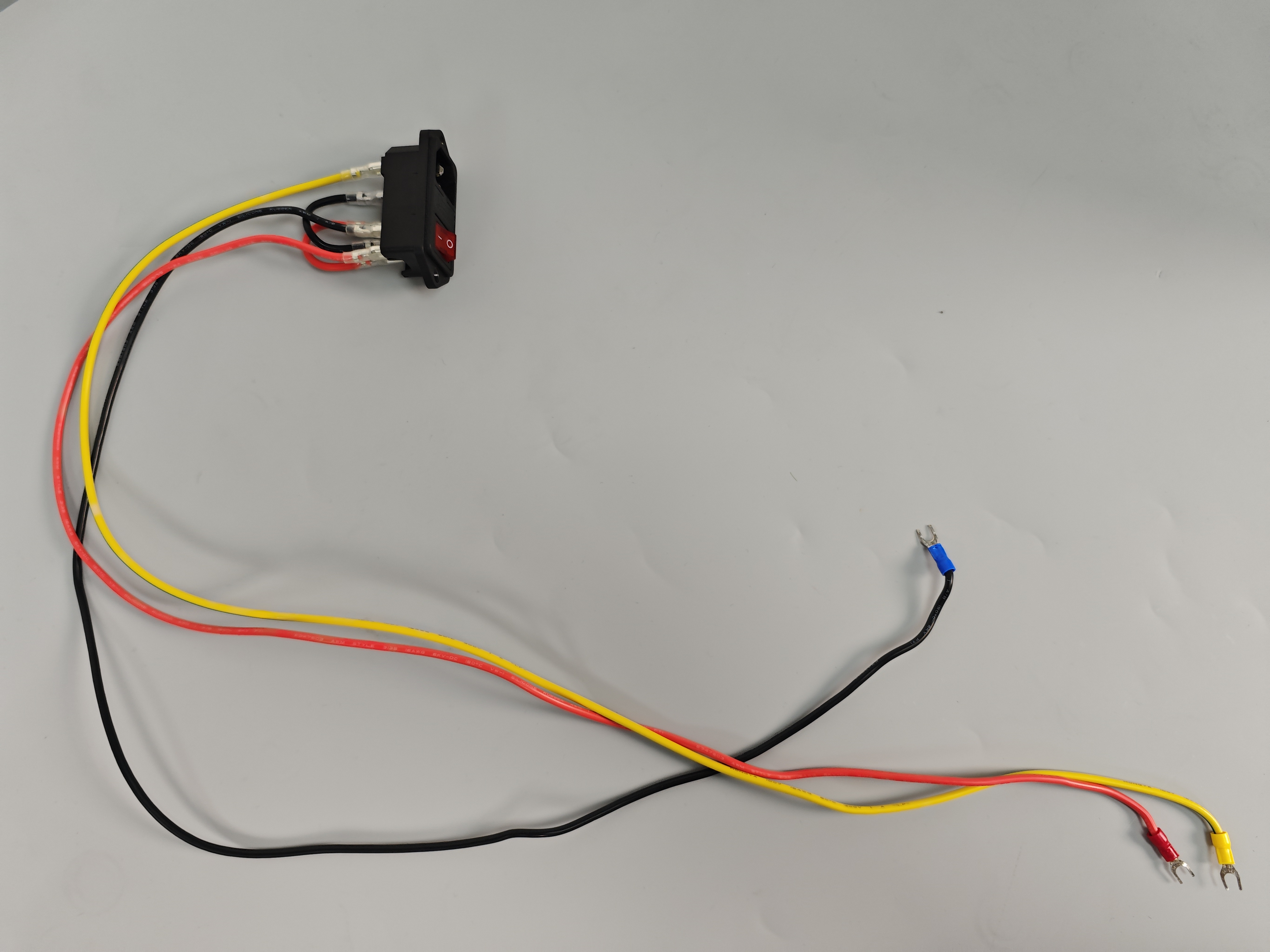
¶ Toggle Switch Replacement
Tools needed
- H2.0 Allen wrench
- Phillips screwdriver
- Pliers
- Zip ties (3 pcs)
- Toggle switch (with wiring)

Precautions and machine status before operation
Before performing any operations, please unplug the power cord and repeatedly press the switch to ensure complete power discharge.
Toggle switch wiring diagram

¶ Operation steps
- Power off and unplug the power cord. Use an H2.0 Allen wrench to loosen the two screws securing the switch holder.

- Place the machine on its side and use an H2.0 Allen wrench to loosen the screws securing the bottom cover.

- Open the bottom cover from the side and disconnect the interface of the motherboard cooling fan.


- Use a Phillips screwdriver to loosen the three wire terminals of the toggle switch on the power supply.


- Use pliers to cut the three zip ties securing the toggle switch cables.


- Remove the toggle switch along with the cables and replace it with a new toggle switch assembly.

- Insert the red cable into the positive terminal (L) of the power input and tighten the screw with a Phillips screwdriver.

- Insert the black cable into the negative terminal (N) of the power input and tighten the screw with a Phillips screwdriver.

- Insert the yellow-green dual-color cable into the ground terminal of the power input and tighten the screw with a Phillips screwdriver.


- Use zip ties to secure the cables at the three attachment points and trim off the excess.


- Align the bottom cover with the installation holes and place it in position.

- Finally, connect the motherboard cooling fan’s interface to the FAN6 port on the motherboard. Use an H2.0 Allen wrench to tighten the screws securing the bottom cover.


- Use an H2.0 Allen wrench to loosen the two screws securing the switch holder.

- Plug in the power and turn on the machine. After successful startup, test the printer’s movement and heating functions. If they are working normally, the printer is ready for regular use.

