Replacement of X-Axis Plastic V-Wheels
Tools and materials needed
- 2.0mm Allen wrench
- 2.5mm Allen wrench
- 3.0mm Allen wrench
- 10mm open-end wrench
- Needle-nose pliers
Reference video
Precautions and Machine Status Before Operation
Please ensure that the machine is turned off and unplugged before proceeding with this operation.
¶ Operation steps
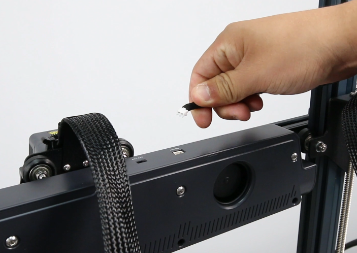
Turn off the printer and disconnect the fan assembly cable at the back of the printhead. Use a 2.5mm Allen wrench to loosen the four screws securing the rear fan assembly and remove it.


Replacing the Upper V-Wheels on the X-Axis Aluminum Extrusion

- Use needle-nose pliers to hold the nut behind the V-wheel and use a 3.0mm Allen wrench to loosen the screw securing the V-wheel.

- Remove the nut while holding the screw with one hand to prevent the components from falling.


- Remove the old V-wheel and slide the new V-wheel onto the screw shaft (ensure that the V-wheel fits snugly into the groove of the X-axis aluminum extrusion).

- Use a 3.0mm Allen wrench to tighten the screw securing the V-wheel.

Replacing the Lower V-Wheels on the X-Axis Aluminum Extrusion

- Use a 2.0mm Allen wrench to loosen the two screws securing the ribbon cable holder and one screw securing the printhead assembly.


- Press the terminal blocks on both sides to release the printhead ribbon cable. Remove the cable.

- Use a 2.0mm Allen wrench to loosen the two screws securing the printhead front cover and remove the printhead assembly.


- Use needle-nose pliers to hold the nut behind the V-wheel. Use a 3.0mm Allen wrench to loosen the screw securing the V-wheel.

- Remove the nut while holding the screw with one hand to prevent the components from falling.


- Remove the old V-wheel and slide the new V-wheel onto the screw shaft. Before installation, ensure that the eccentric spacer is properly positioned (make sure the V-wheel fits snugly into the groove of the X-axis aluminum extrusion).


- Use a 3.0mm Allen wrench to tighten the screw securing the V-wheel.

- Place the printhead assembly back in the front installation position, and use a 2.0mm Allen wrench to tighten the two screws securing the printhead front cover.


- Press the terminal blocks on both sides to open the port, then insert the printhead ribbon cable into the port (ensure that the cable passes through the bottom of the top extrusion).

- Use a 2.0mm Allen wrench to tighten the two screws securing the ribbon cable holder and one screw securing the printhead assembly.

- Align the fan assembly with the screw holes and use a 2.5mm Allen wrench to tighten the four screws securing the rear fan assembly (install with the air outlet facing downwards). Plug in the fan assembly connector cable.


- Check if the printhead has any vertical wobble or exhibits rough sliding motion horizontally.


- Use a 10mm open-end wrench to adjust the eccentric spacer of the X-axis V-wheel.

- While adjusting, slide the V-wheels manually and ensure they make smooth contact with the aluminum extrusion without being too tight or loose.

- Power on the printer and tap “Prepare” on the touch screen. Select the “all” icon in the center to home all axes. After the printer finishes homing, re-level it for normal use.
