Extruder Gearbox Replacement
Tools and materials needed
●H2.0 Allen wrench
●H2.5 Allen wrench
●Philips screwdriver
●Extruder gearbox
Reference video
Precautions before operation and machine status
Before performing the operation, please turn off the machine and wait for the print head to cool down completely.
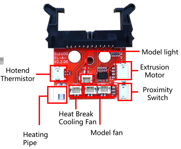
Extruder Controller Board Wiring Diagram

Operation steps
1-Remove the print head
1. Power off the printer, unplug the port cable of the fan assembly located directly behind the print head, use an H2.5 Allen wrench to loosen the four fixing screws of the "rear fan assembly", and remove the rear fan assembly.


2. Use an H2.0 Allen wrench to loosen the two fixing screws of the "cable fastener" and the one fixing screw of the whole print head assembly.


3. Press the "horn terminal" on both sides with your hands, the print head cable will pop up automatically, and then take out the print head cable.

4. Use an H2.0 Allen wrench to loosen the two fixing screws of the "print head front cover" and remove the whole print head assembly.


2-Replace the extruder gearbox
1. Separate the front cover of the print head assembly, and use a Phillips screwdriver to loosen the four fixing screws on the left and right sides of the "fan bracket".


2. Unplug the cables connected to the extruder controller board, remove the "fan bracket" assembly downwards, and unplug the cables of the extruder motor from the extruder controller board.


3. Use a Phillips screwdriver to loosen a fixing screw on the extruder controller board and remove the extruder controller board.

4. Use an H2.0 Allen wrench to loosen the two screws fixing the "hot end" and take out the "hot end" and the light blue "Teflon tube".


5. Use a 2.0mm Allen wrench to loosen the two screws fixing the "extruder motor" and remove the extruder motor.

6. Take out the new extruder gearbox, align the extruder motor with the bearing holes, and put it in the mounting position. Use an H2.0 Allen wrench to tighten the two fixing screws of the "extruder motor".

7. Take out the "hot end" and Teflon tube and place them in the installation position (Teflon tube chamfered end facing up).


8. Use an H2.0 Allen wrench to loosen the two screws fixing the "hot end".

9. Align the extruder controller board with the screw holes and place it in the installation position, and use a Phillips screwdriver to tighten the fixing screws.

10. Insert the cable of the ceramic heating element into the "HE" port of the extruder controller board, and the thermistor cable into the "TH" port of the extruder controller board.

11. Insert the extruder motor cable into the "E0" port of the extruder controller board.

12. Place the "fan bracket" assembly into the installation position (aligning the screw holes on both sides for easier installation), and use a Phillips screwdriver to tighten the four fixing screws of the "fan bracket".


13. Insert the model cooling fan cables into the "FAN2" ports of the extruder controller board (The two FAN2 ports on the extruder controller board are compatible with each other, no need to distinguish).

14. Insert the nozzle light cable into the "LED" port of the extruder controller board.

15. Insert the throat cooling fan cable into the "FAN1" port of the extruder controller board.

16. Insert the proximity switch cable into the "PS" port of the extruder controller board.

3-Install the print head
1. Install the front cover of the whole print head assembly (It has a groove design and can be installed by sliding it in).

2. Place the whole print head assembly into the mounting position in front of the print head, and use a 2.0mm Allen wrench to tighten the two fixing screws of the "print head front cover".


3. Press the "horn self-locking terminal" to both sides with your hands to open the port, and then insert the print head cable into the port (note that the cable passes under the top profile).

4. Use a 2.0mm Allen wrench to tighten the two fixing screws of the "cable fastener" and the one fixing screw of the print head.

5. Align the fan assembly with the screw holes, use a 2.5mm Allen wrench to tighten the four fixing screws of the rear fan assembly (install with the air outlet facing downwards), and insert the fan assembly into the cable port.


6. Turn on the printer power, click [Prepare-Temperature] on the touch screen, and then set the nozzle temperature to 210°C in the temperature control interface.

7. Press the extruder handle to feed the filament into the extruder. Click "Extruder" on the touch screen. After setting the length of the extruded filament, click "Load".


8. After observing that the nozzle extrudes filaments normally, re-level the printer and it can be used normally.
