¶ 1. Introduction to ELEGOO SatelLite
ELEGOO SatelLite (Version: 1.0.0.52) is a slicing software designed for resin 3D printing. It converts 3D model files into printable formats that are compatible with printers. With this software, users can process models and configure printing parameters to ensure high-quality results.
For instance, users can select the appropriate resin, adjust exposure times, scale models, and add supports to the model as needed.
Formats of the Exported Files
ELEGOO SatelLite supports the import of .stl, .obj, and .3mf, etc. files. Typically, the exported format is *.goo. To export in other formats, users can install the UVtools plug-in to convert the file types.
Requirements for Hardware
| Component | Requirements |
|---|---|
| CPU | - Intel Core i5 6600K or higher - AMD Ryzen 5 1600 or higher - Apple M1 Max or higher |
| Display | - 1920 × 1080 resolution or higher - 2560 × 1440 resolution recommended |
| Video Card | - NVIDIA GeForce GTX 1050 or AMD Radeon RX 480 or higher - Minimum 1 GB of RAM - Supports OpenGL 3.0 |
Note: Any Intel GPU chipset is not recommended.
Computer Operating System
| Category | Supported Systems |
|---|---|
| Supported System | - Windows 10 64-bit (recommended) - Windows 7 64-bit SP1 or later - Windows 8/8.1 64-bit - Windows 11 64-bit - macOS Monterey 12.0.1 or later |
| Unsupported System | - Windows Server versions - Virtualization systems such as VMware |
¶ 2. Installation
¶ 2.1 Installation Steps
After downloading the installation package, follow the steps below to complete the installation process.
- Unzip the installation package, then double-click the installation program to display the installation guide.

- Follow the installation guide to complete the installation process.
Click Next.

- Tick I accept this license agreement, and then click Next.

- Customize the installation settings and choose the installation location, or select the default settings. Then, click Next.

- The installation process starts.

- The installation completes.

¶ 2.2 Tutorial Guide
- After completing the installation, click Start for initial settings.

- Wait for loading.

- After the User Guide appears, follow the prompts to select the language and theme as needed.


- Users can choose between Advanced or Beginner.

¶ 2.3 Uninstallation
Follow the steps below to uninstall the software.
Ensure that the software is closed before proceeding with the uninstallation.
- Click the Windows icon at the bottom left corner of the desktop and then find ELEGOO SatelLite.
- Click the Windows icon at the bottom left corner of the desktop, and then locate ELEGOO SatelLite.

- Right-click the ELEGOO SatelLite icon and then click Uninstall.

- In the Uninstall Guide interface, click Next.

- Users can tick Delete Personal Data according to their preferences. Click Confirm to finalize the uninstallation process.


¶ 3. User Registration
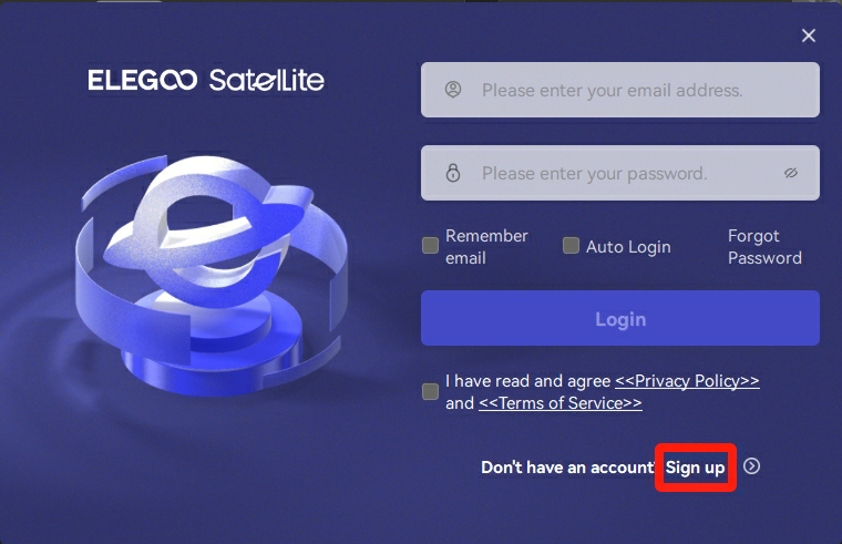
The user registration interface appears after selecting an identity. Follow the steps below to complete the registration process.
Note: ELEGOO SatelLite supports offline use; however, an account is required for cloud resin import. A valid email account is necessary for registration.
- Click "Sign Up", and then the registration interface appears.
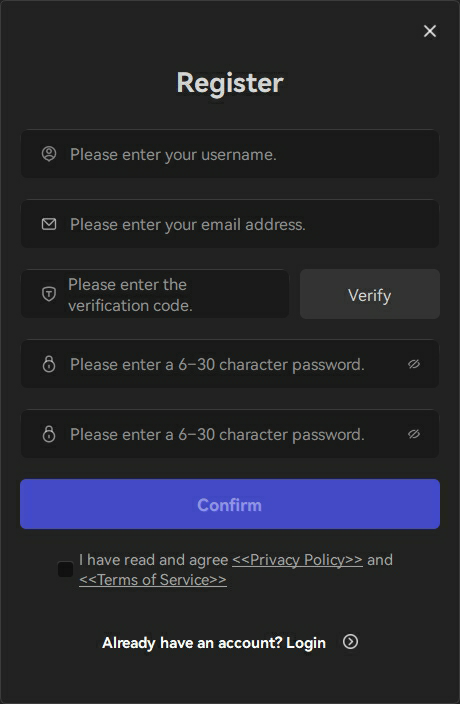
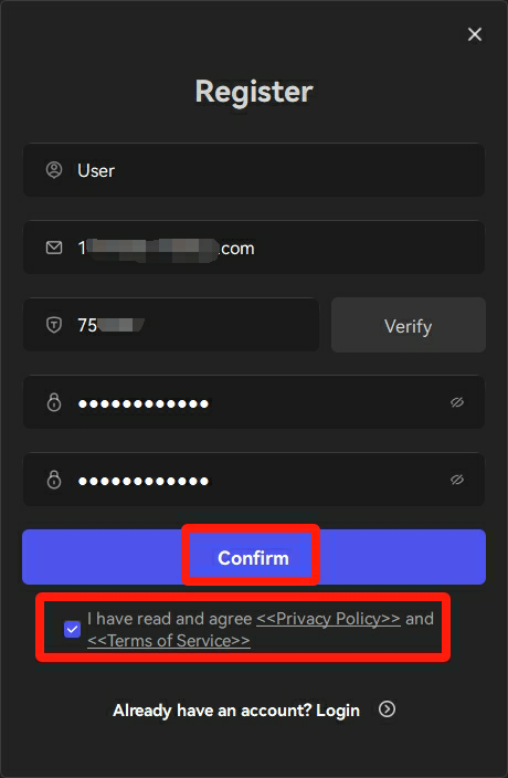
- Enter the registration information, tick "I have read and agree Privacy Policy and Terms of Service." Click "Confirm" to complete the registration process.
(Privacy Policy and Terms of Service protect users' privacy and govern the use of the software.)
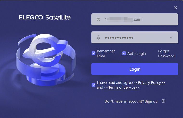
- Type your registered email address and password to log in. Tick "I have read and agree Privacy Policy and Terms of Service.", and click "Login".
(Users can select "Remember me" and "Auto Login" according to their preferences.)
¶ 4. Function
¶ 4.1 Printer and Resin Addition
¶ 4.1.1 Printer and Resin Addition
Adding the Printer
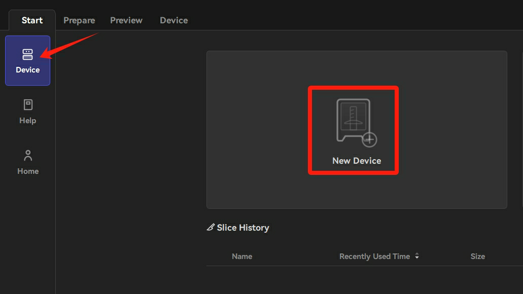
- In the Start interface, click "Device" at the left side and then click "New Device".
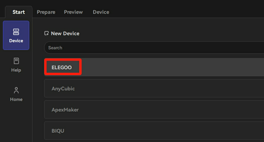
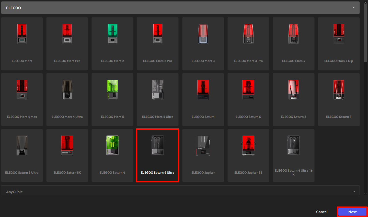
- Click "ELEGOO" and then select the appropriate printer. Click "Next".
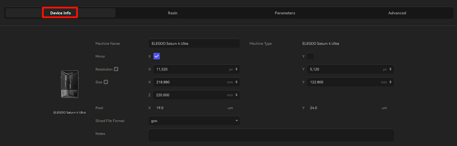
- After successfully adding the printer, the configuration list displays the basic information about the printer.
Adding the Resin
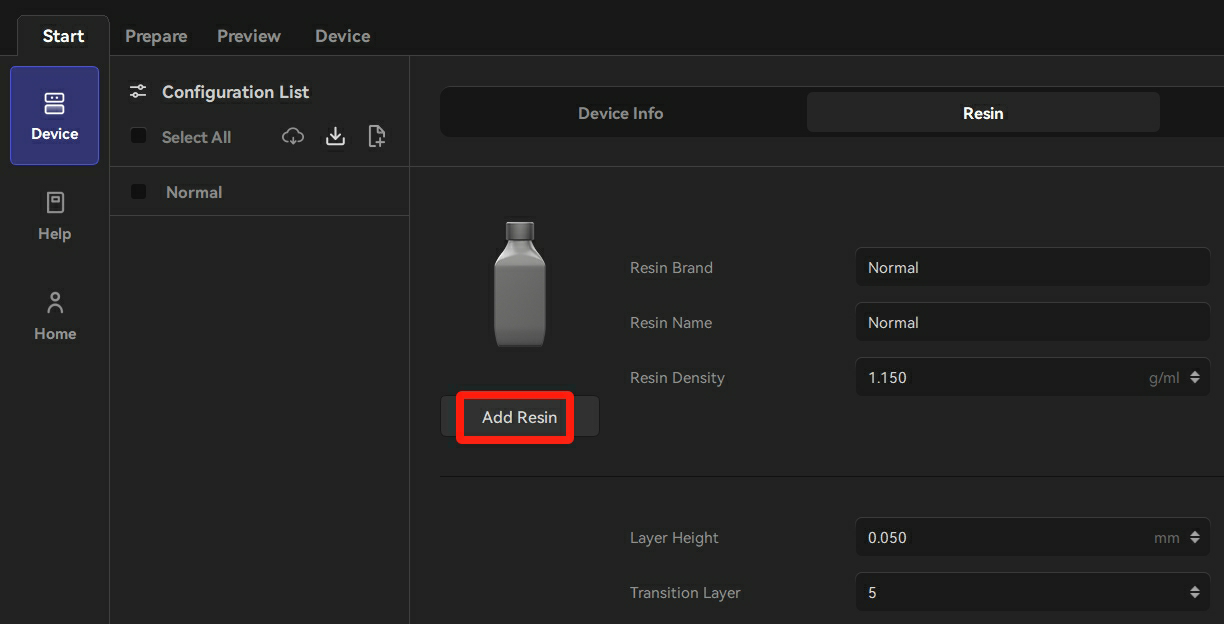
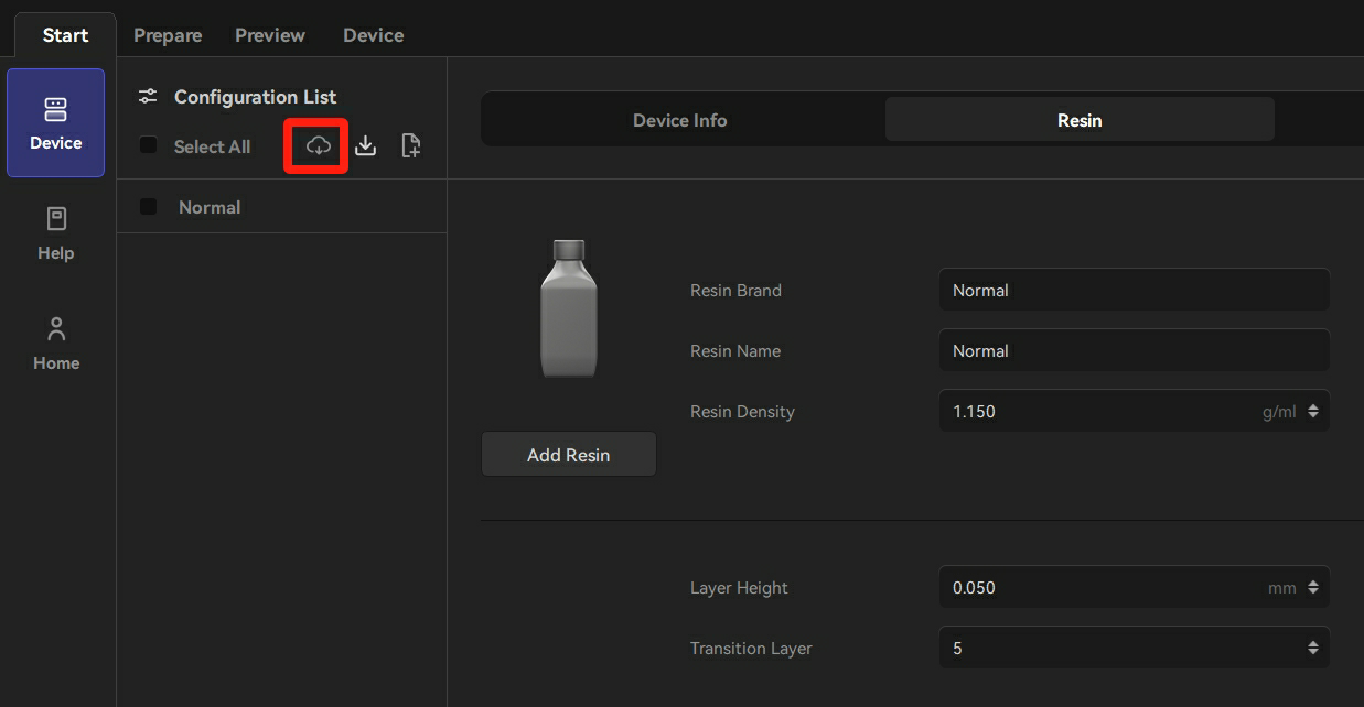
- Click "Add Resin" or the "Cloud Import" icon at the left side. (If users choose the "Cloud Import" option to add resin, logging into the account is not required.)
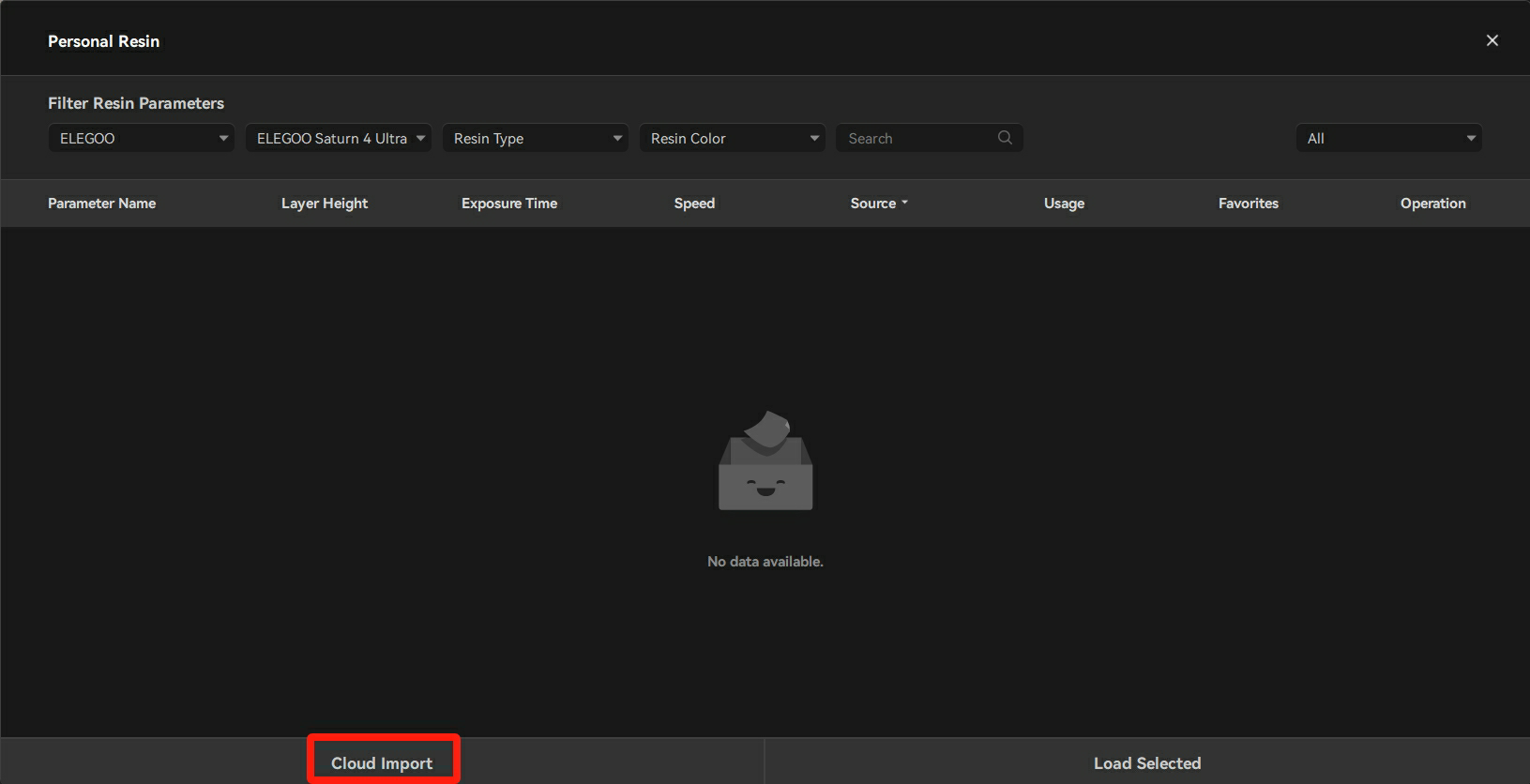
- Click "Cloud Import" in the Personal Resin pop-up window.
- Select the type and color of resin that is compatible with the printer from the official resin library.
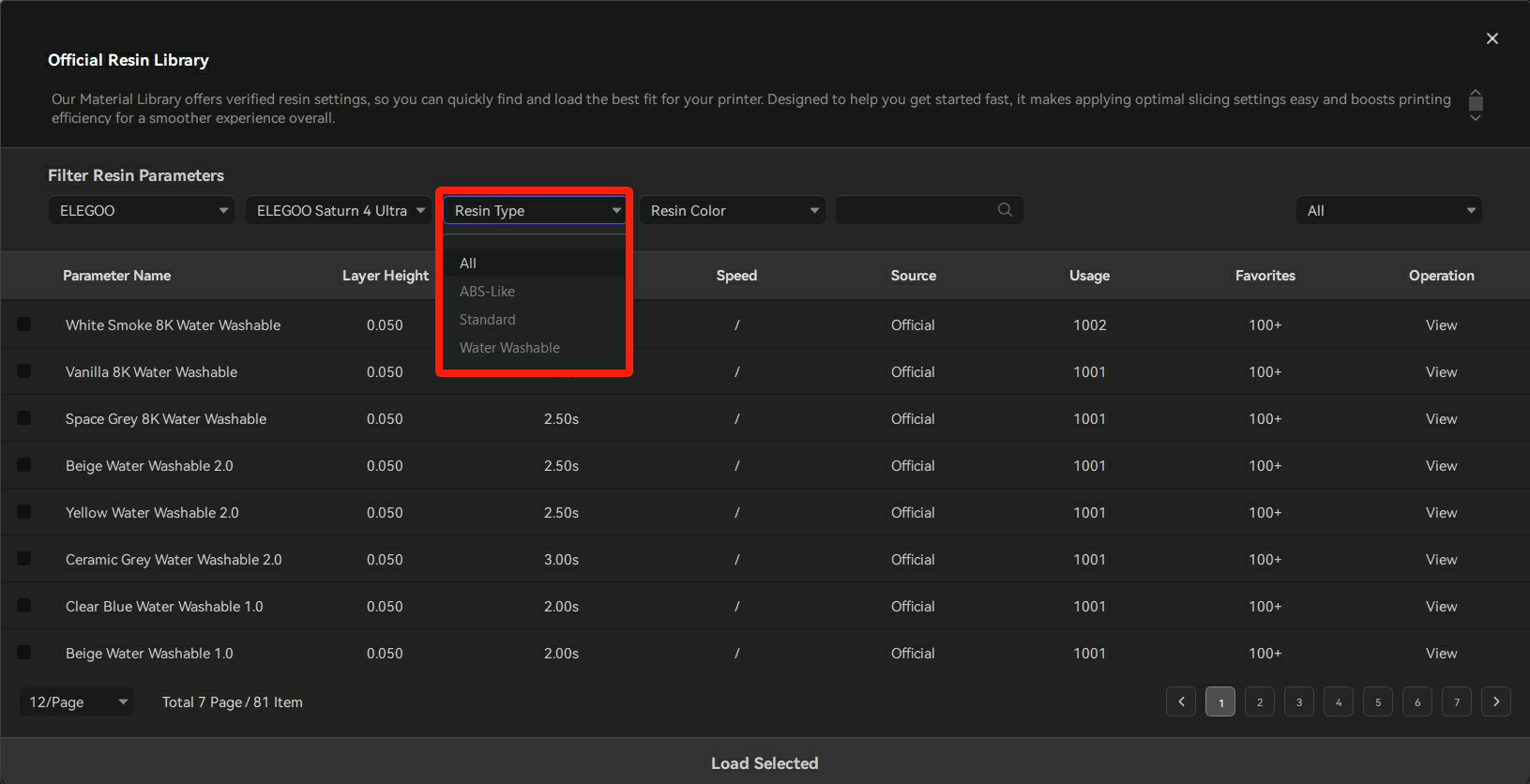
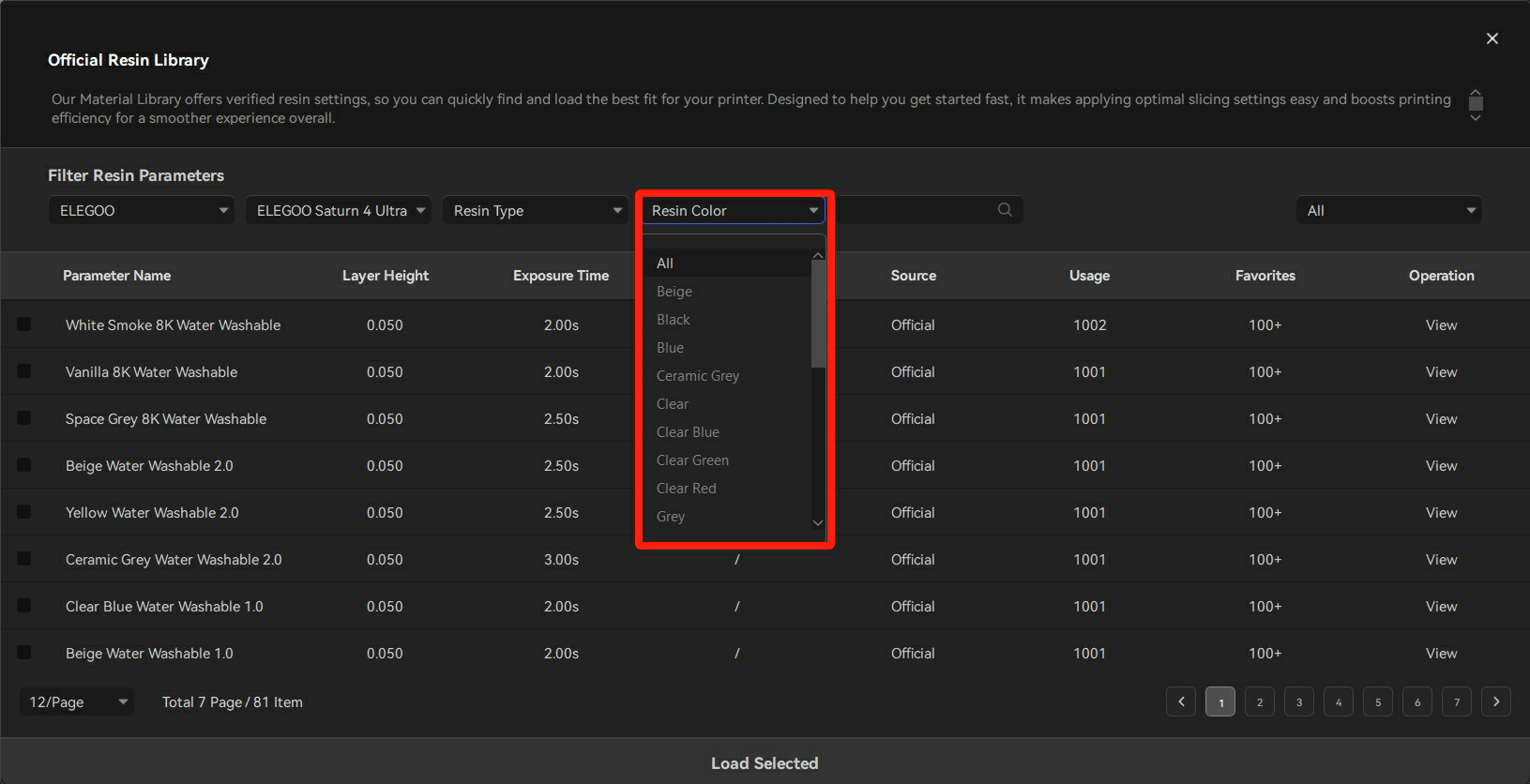
- Tick the appropriate resin and click "Load Selected" at the bottom of the interface.
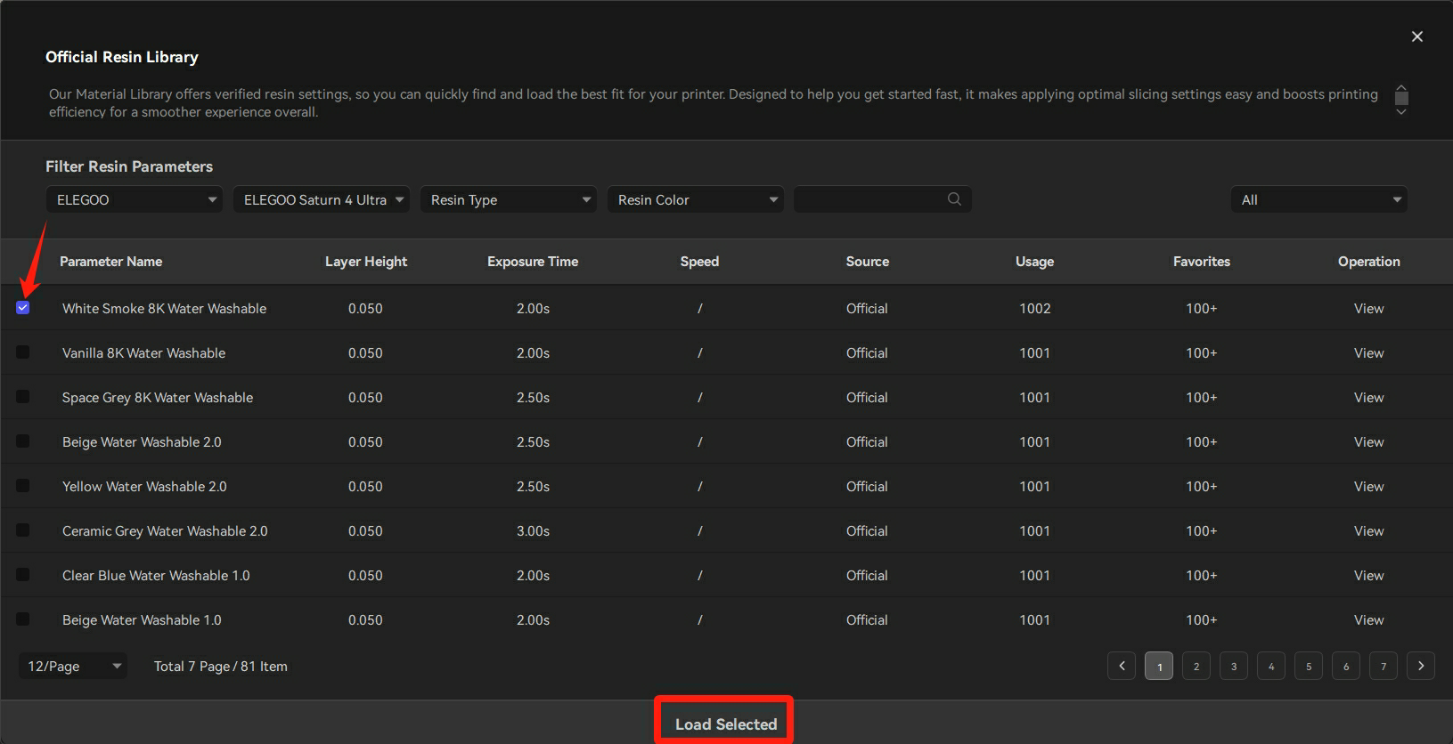
- Tick the resin loaded in the personal resin library and then click "Load Selected".
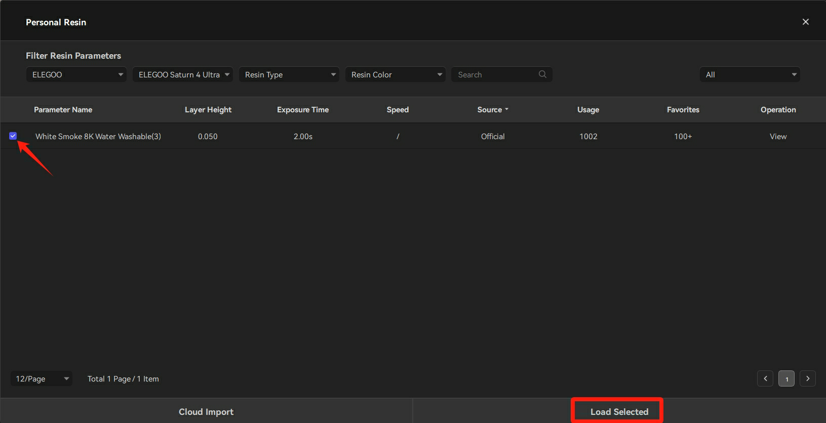
- Tick the resin in the configuration list and then click "Apply".
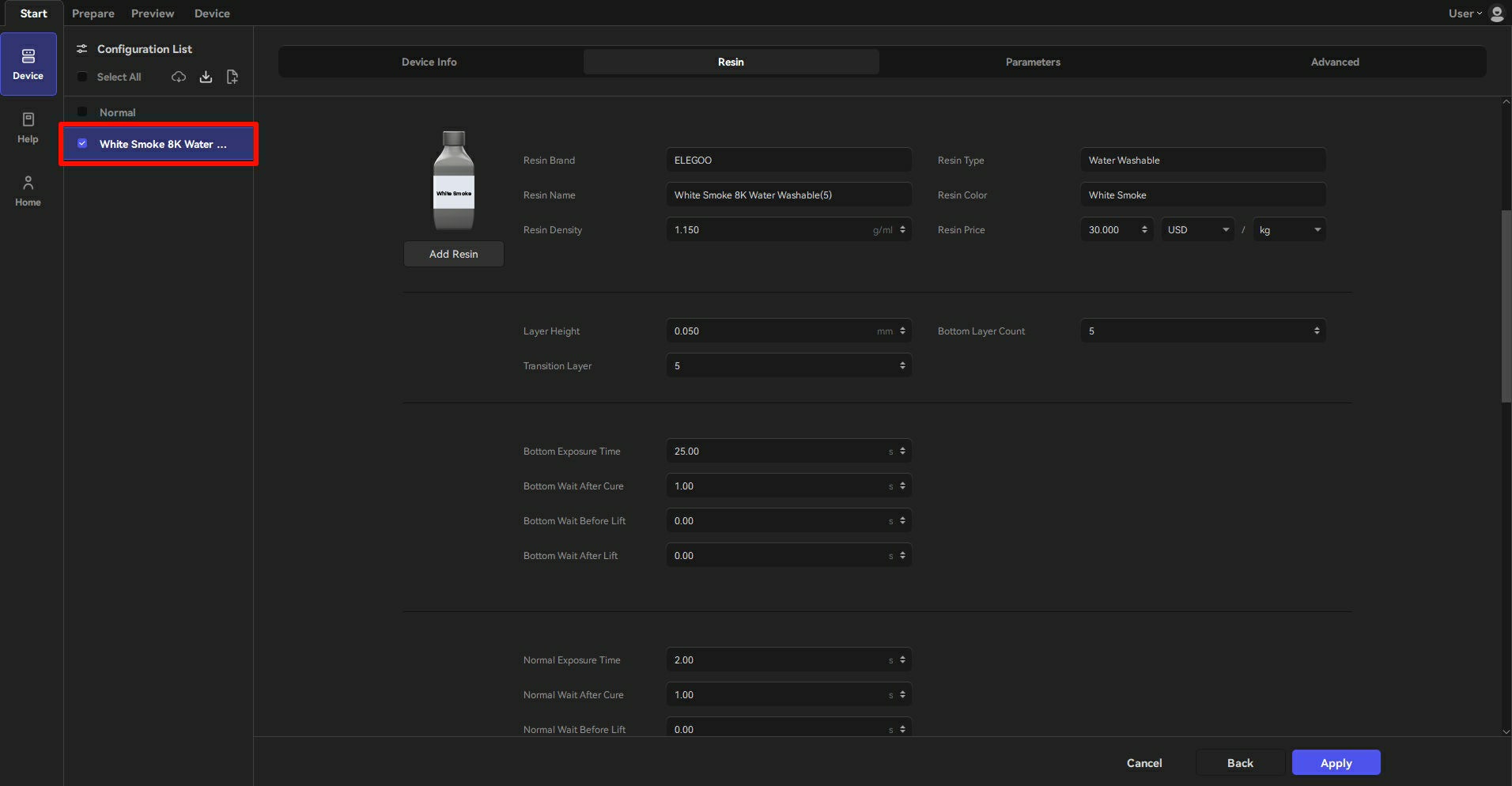
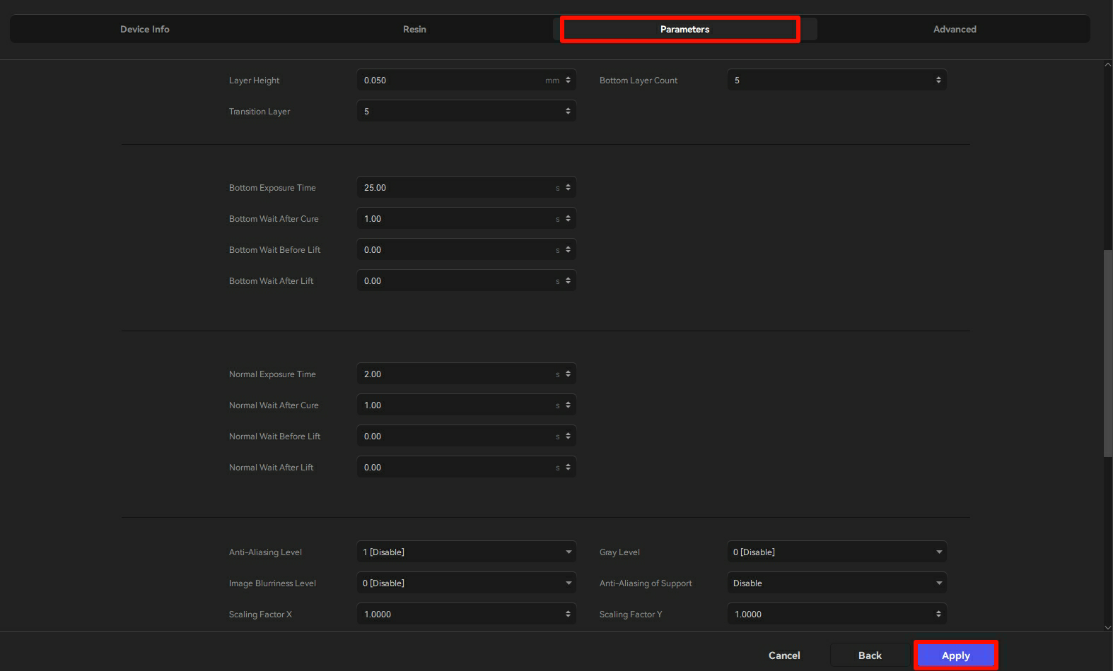
- Click "Parameters" to review the values, and then click "Apply".
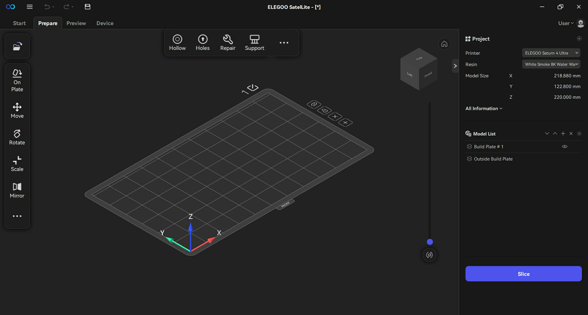
- The printer and resin can be added successfully and the software jumps to the Prepare interface.
¶ 4.1.2 Printing Parameters Setting
As shown in the figure below, after adding the printer and the resin, click "Parameters" and "Advanced" to set the values of printing.
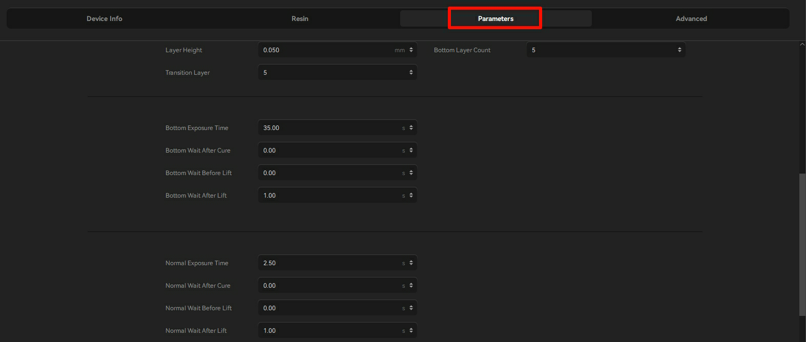
Basic Settings
| Parameter | Explanation |
|---|---|
| Layer Height | Thickness of each layer printed |
| Bottom Layer Count | Number of layers at the beginning of the print (The exposure time of these layers are relatively longer.) |
| Transition Layer | The number between the bottom layers and the normal print layers. The more the transition layers, the better the transition from the normal layers to the bottom layers. |
Bottom Layer Settings
| Parameter | Explanation |
|---|---|
| Bottom Exposure Time | It refers to the exposure time of the bottom layers. If the number of bottom layers is N, it refers to the exposure time of the N layers. |
| Bottom Wait After Cure | It refers to the time that during the bottom-layer printing process, the build plate moves to the printed surface and then wait until re-exposuring. |
| Bottom Wait Before Lift | It refers to the time that during the bottom-layer printing process, the build plate stands for a while and then leaves from the printed surface. |
| Bottom Wait After Lift | It refers to the time that during the bottom-layer printing process, the build plate lifts to designated distance and then stands for a while. |
Normal Layer Settings
| Parameter | Explanation |
|---|---|
| Normal Exposure Time | It refers to the exposure time of the normal layers. |
| Normal Wait After Cure | It refers to the time that during the normal-layer printing process, the build plate moves to the printed surface and then wait until re-exposuring. |
| Normal Wait Before Lift | It refers to the time that during the normal-layer printing process, the build plate stands for a while and then leaves from the printed surface. |
| Normal Wait After Lift | It refers to the time that during the normal-layer printing process, the build plate lifts to designated distance and then stands for a while. |
Advanced Setting
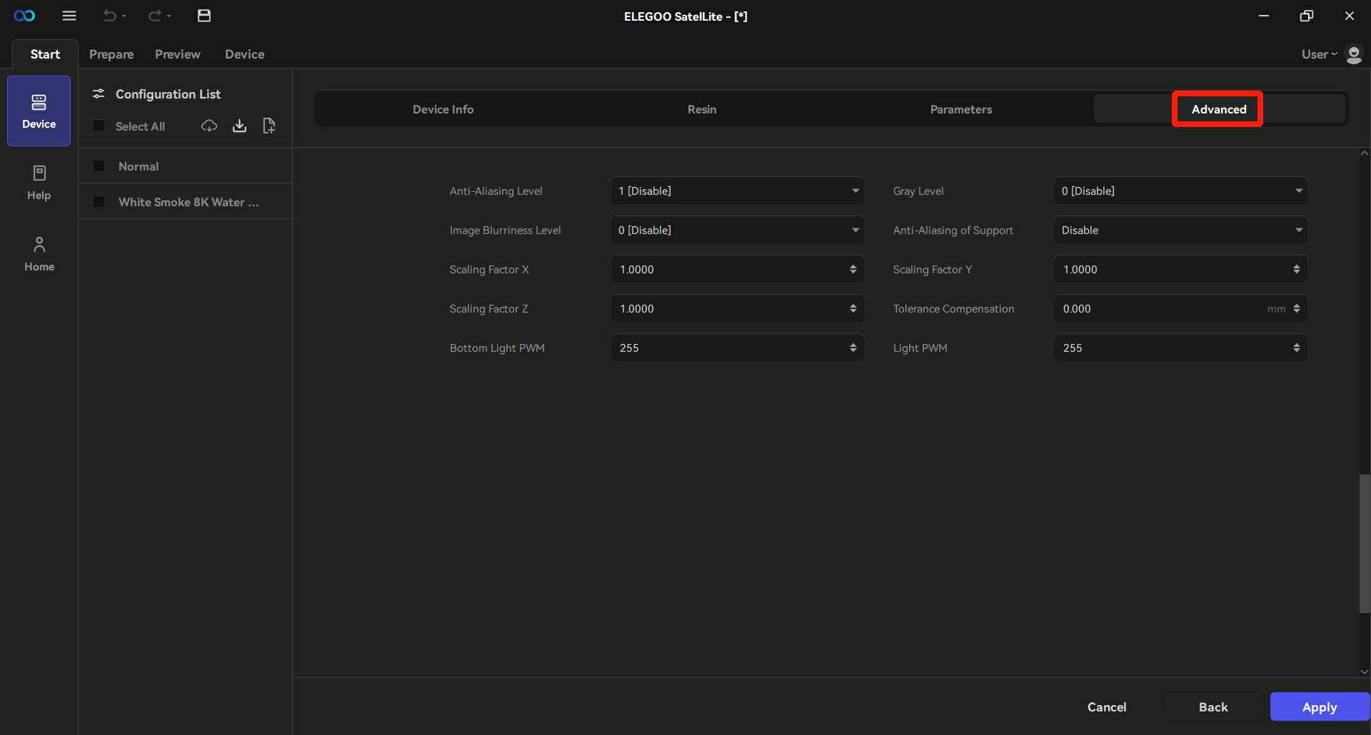
| Parameter | Explanation |
|---|---|
| Anti-Aliasing Level | To reduce the jaggedness of the model's edges. Higher anti-aliasing levels indicate smoother surfaces of the model, with details may be lost. |
| Gray Level | To change the range of gray values of anti-aliasing, which comes into force when the anti-aliasing function is activated. The higher gray level indicates the clearer edge. |
| Image Blurriness Level | To blur the edges of a model and make the transition smoother. The higher blur level means the less clear model edges, with fine lines may be lost. |
| Anti-Aliasing of Support | To support the addition of the anti-aliasing function. It can reduce the strength of the support and is not enabled by default. |
| Scaling Factor X | Scale ratio in the horizontal X-direction. |
| Scaling Factor Y | Scale ratio in the horizontal Y-direction. |
| Scaling Factor Z | Scale ratio in the vertical Z-direction. |
| Tolerance Compensation | The overall scaling ratio of the model. |
| Bottom Light PWM | The adjustment of the UV light PWM during the bottom printing process (range 0-255). |
| Light PWM | The adjustment of the UV light PWM (range 0-255). |
¶ 4.2 Model Import and Process
¶ 4.2.1 Left-Side Toolbar
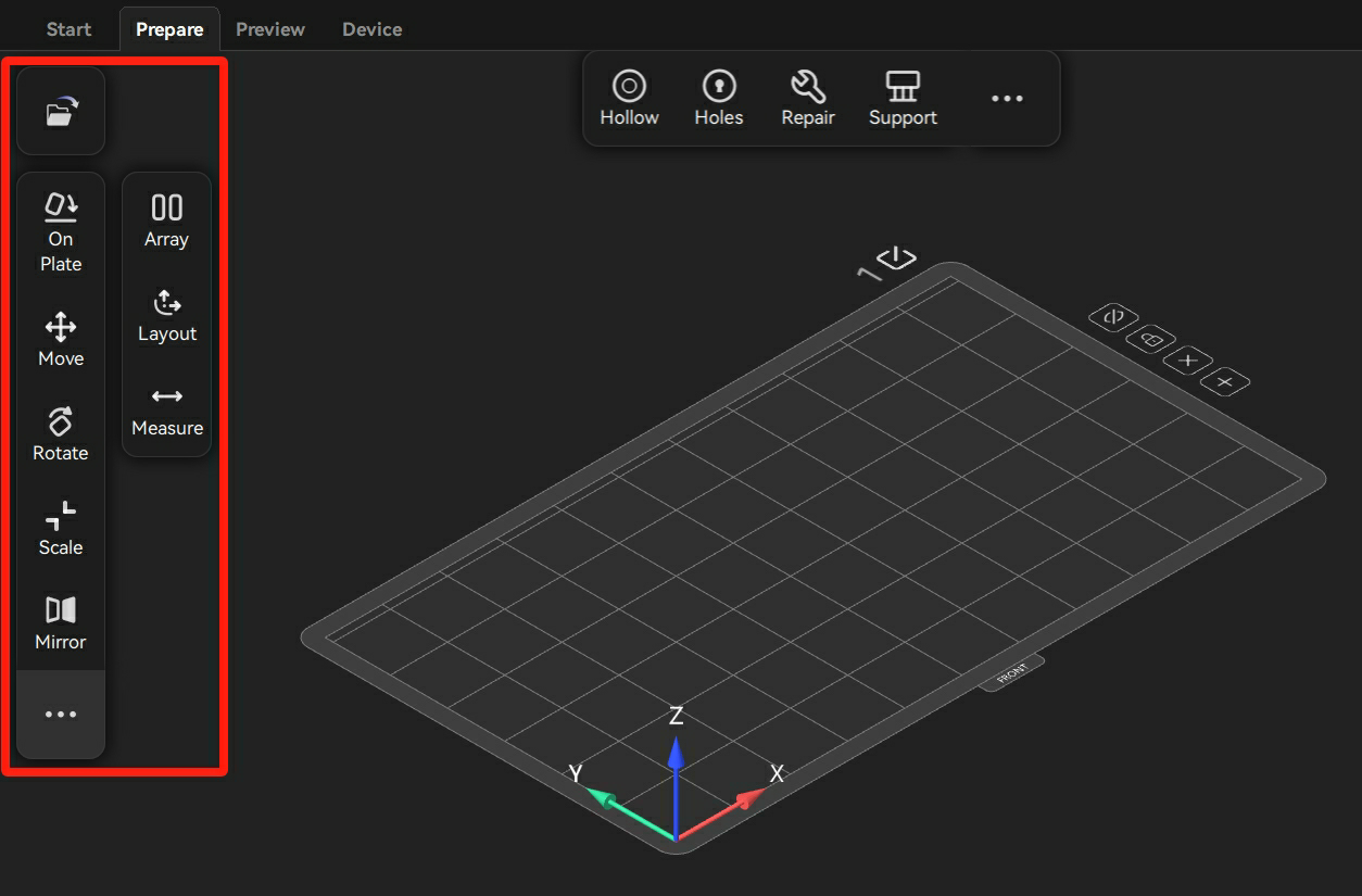
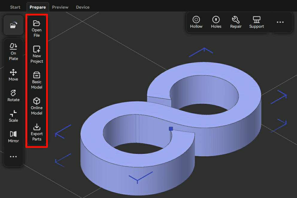
Importing a Model
Click the file icon to import the model as required. After the import is successful, the model appears on the build plate.
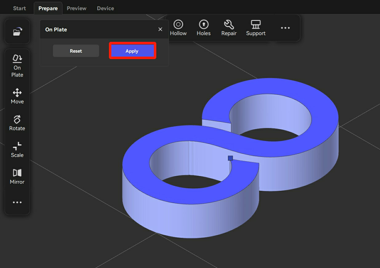
On Plate (Shift+B)
Users can select the surface to designate it as the bottom surface by clicking the "On Plate" button.
Click "On Plate", and then click the selected surface. Click "Apply" to confirm.
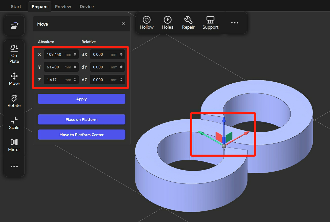
Move (M)
Users can move the model to the specified position by clicking "Move".
There are two methods to move the model:
- Drag the model to move.
- Modify the coordinate values and then click "Apply" to move the model.
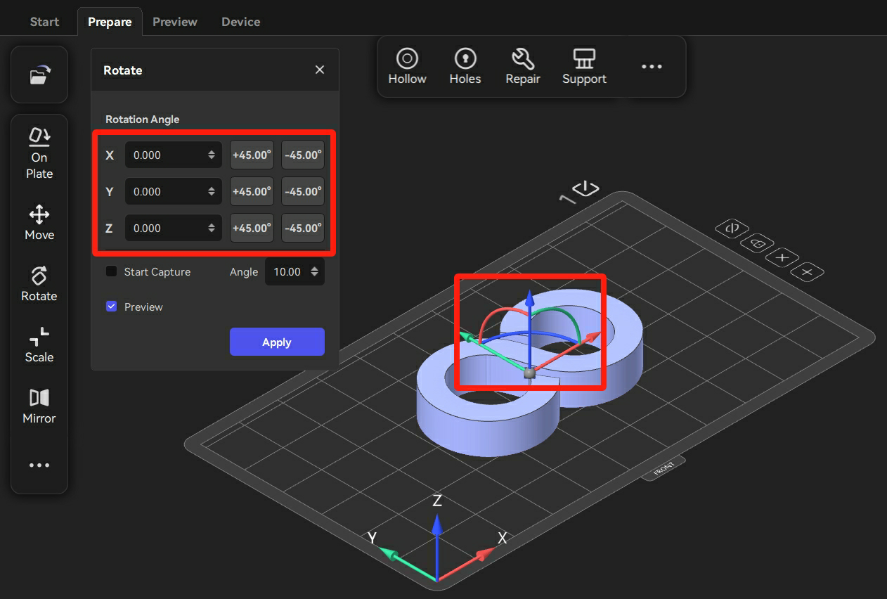
Rotate (R)
Users can rotate the model by clicking "Rotate".
There are two methods to rotate the model:
- Select the axes on the model, and then rotate the model to the appropriate angle.
- Adjust the rotation angle or click the "45°" angle to rotate the model.
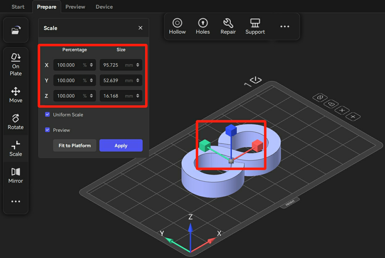
Scale (S)
Users can scale up/down the model by clicking "Scale".
There are two methods to scale up/down the model:
- Scale up/down the model size by dragging the axes on the model.
- Modify the value of "Percentage" or the value of "Size" and then click "Apply" to scale up/down the model.
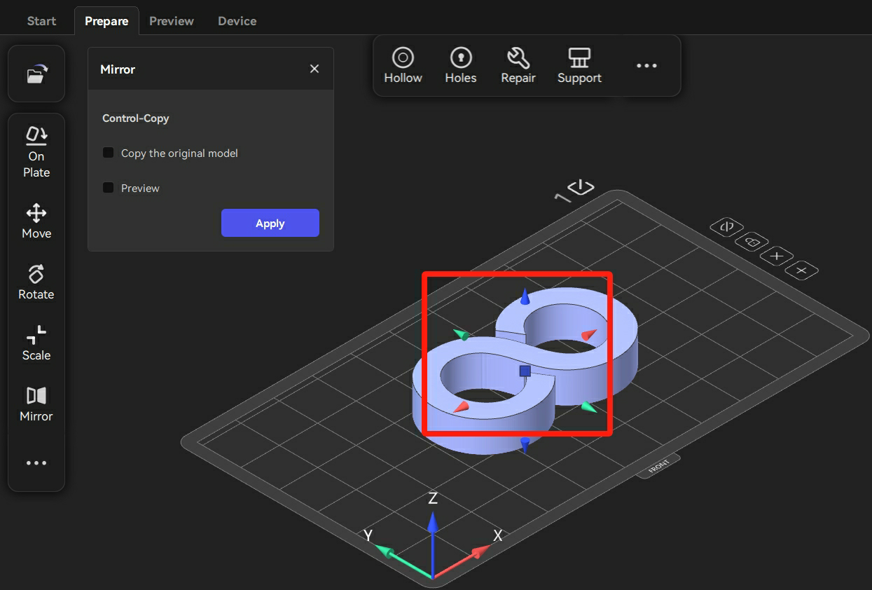
Mirror (Ctrl+M)
Users can mirror the model by clicking "Mirror".
Click "Mirror" and then click the arrow in the direction as needed to mirror the model.
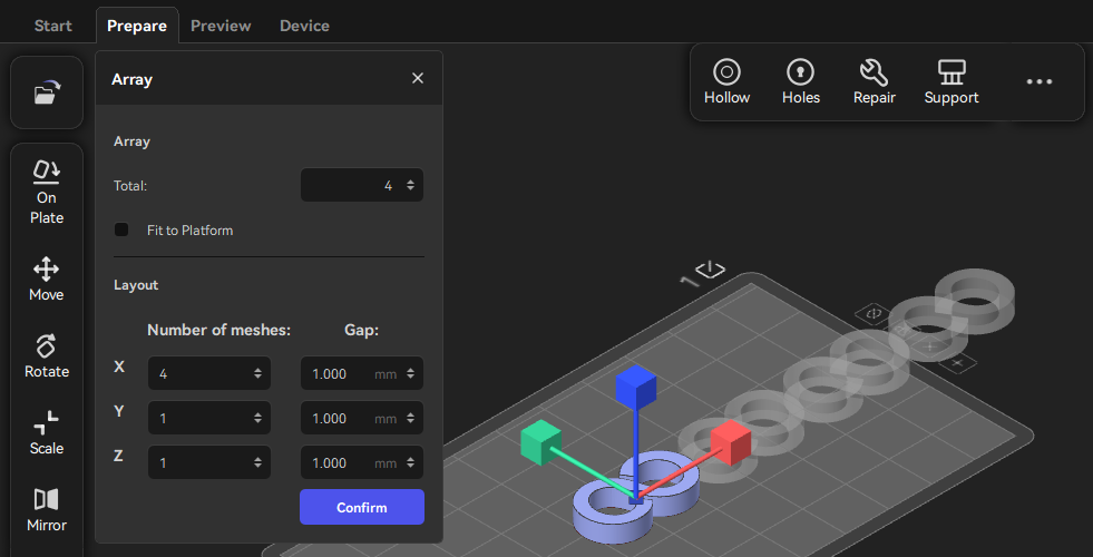
Array (Ctrl+D)
Users can duplicate and array models by clicking "Array".
- Click "Array" and then modify the value of "Total".
- Click "Confirm" to duplicate and array the models.
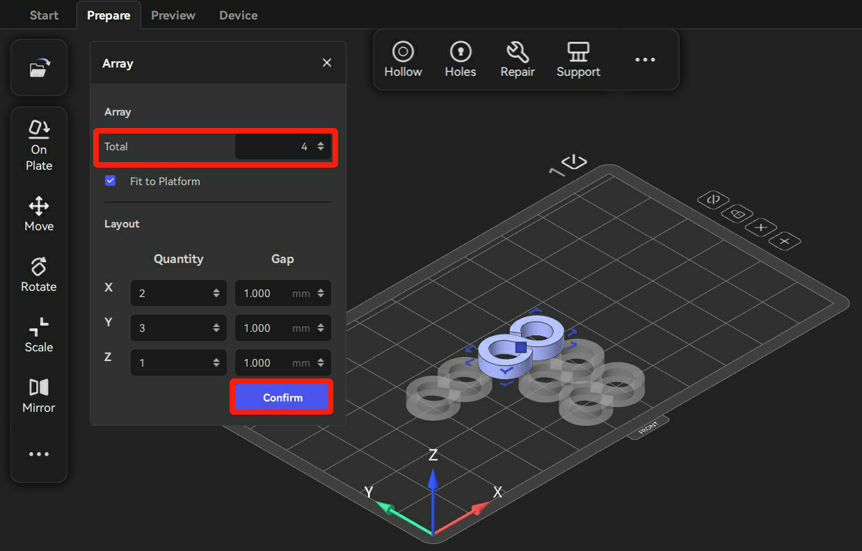
- After modifying the "Total", users can uncheck "Fit to platform". Then, the number of models distributed along each axis can be adjusted based on users' demands.
Layout (Shift+A)
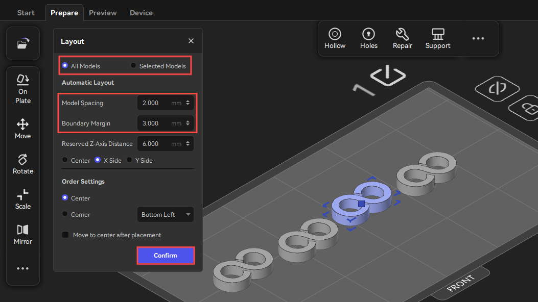
Users can rearrange the models by clicking "Layout".
- Click "Layout", and then users can choose either "All Models" or "Selected Models" to rearrange the models.
- According to the printing requirements, users can adjust the model spacing and boundary margin.
- Click "Confirm" to finalize the new positions of the models.
Measure (Shift+M)
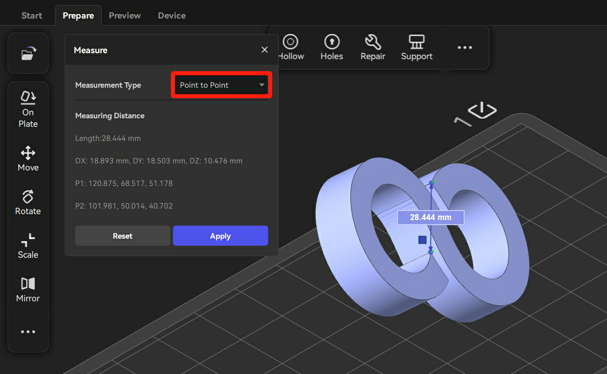
Users can measure the distance either between two points or between a point and the platform.
- Choose "Point to Point" measurement type.
- Select the two points on the model that need to be measured, and then the distance value will be displayed.
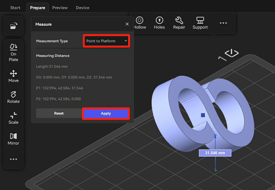
- Choose "Point to Platform" measurement type.
- Select a point on the model to be measured and then the distance value appears.
- Click "Apply", and then the values remain.
¶ 4.2.2 Top Toolbar
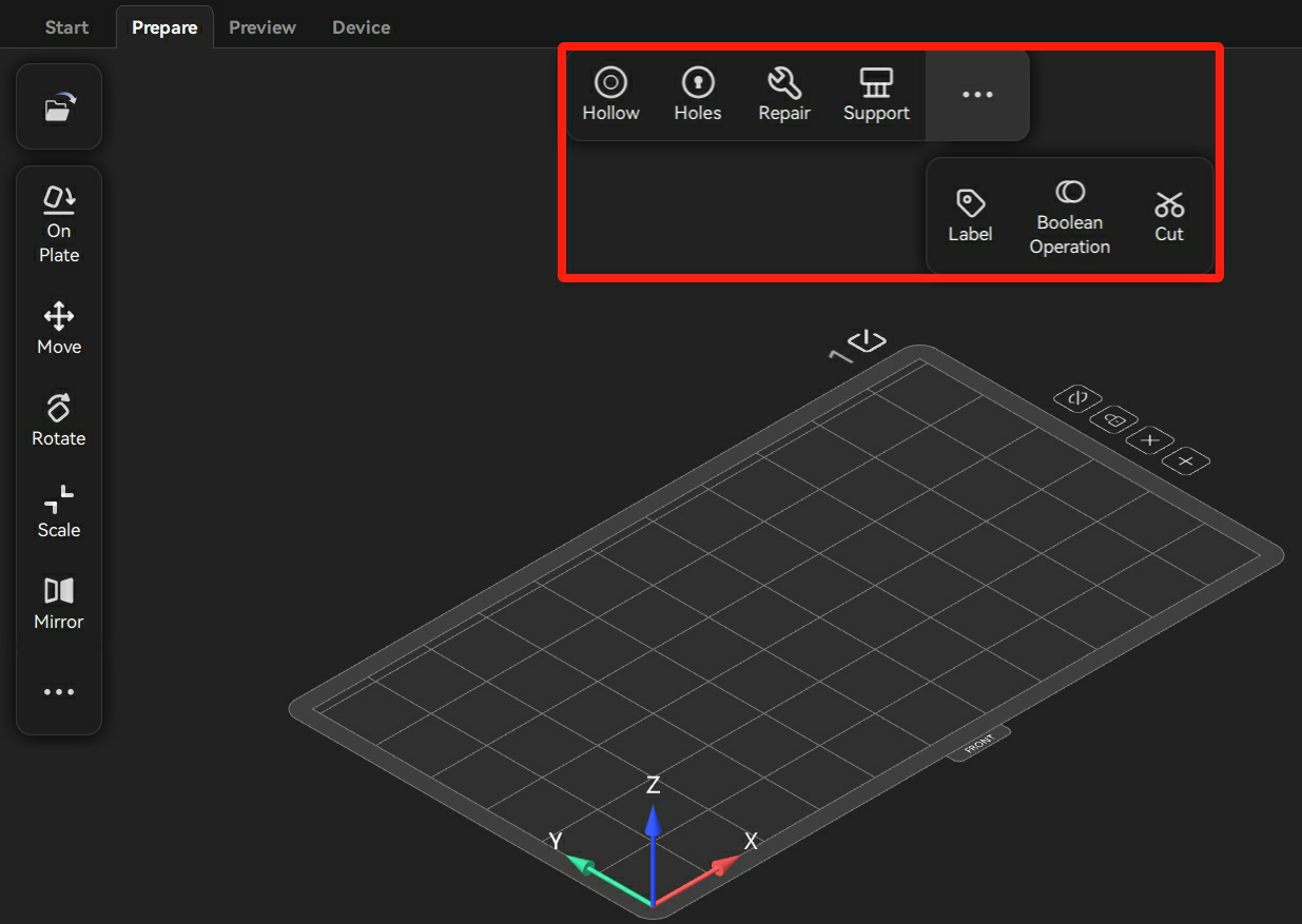
Hollow (Alt+H)
Users can hollow out the model by clicking "Hollow" to reduce the quantity of resin to be used.
After clicking "Hollow", users can set the parameters in the Hollow pop-up window. Then, click "Confirm" to hollow out the model.
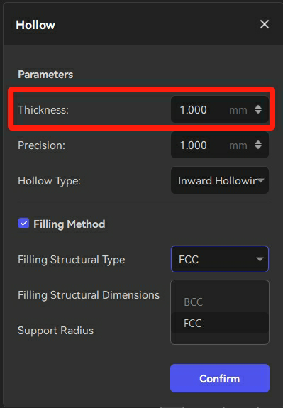
Thickness: The thickness of the shell. It influences the strength of the model.
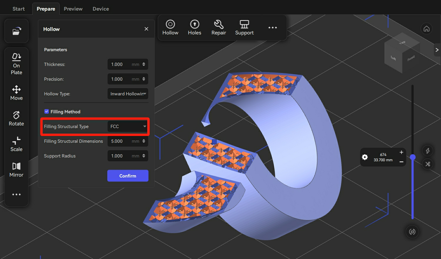
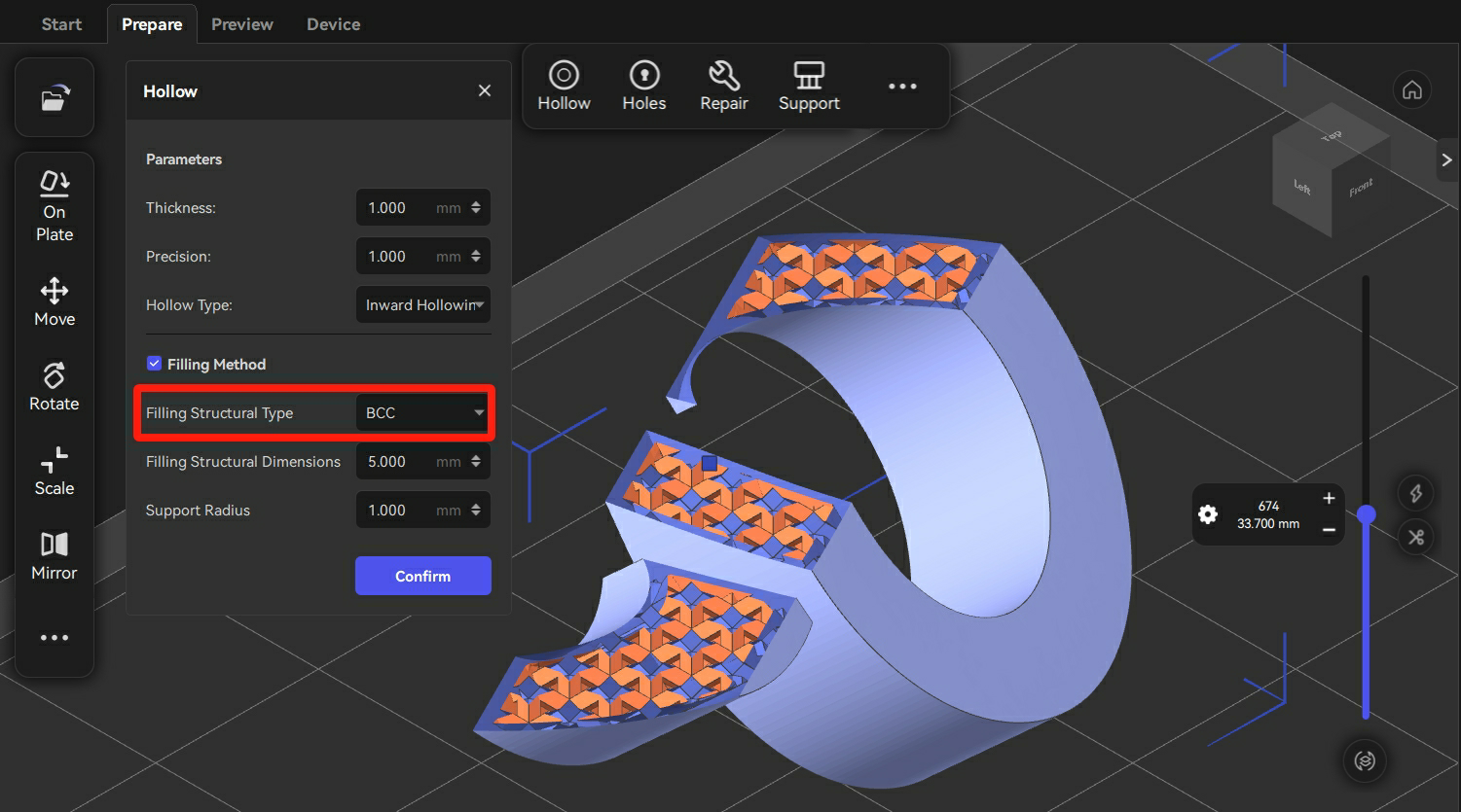
Filling Method: There are two different types of filling structures to choose.
Holes (Shift+P)
It is necessary to add holes to the hollowed models.
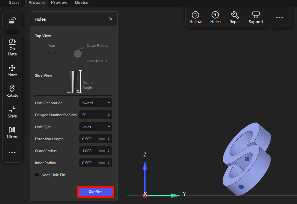
Note: To prevent the vacuum zone in the center of the model and to facilitate the cleaning of resin, it is necessary to add at least 2 holes to hollowed models, with one at the bottom and the other at the top.
- Click "Holes" and then users can set the "Extension Length", "Outer Radius", and "Inner Radius" in the Holes pop-up window.
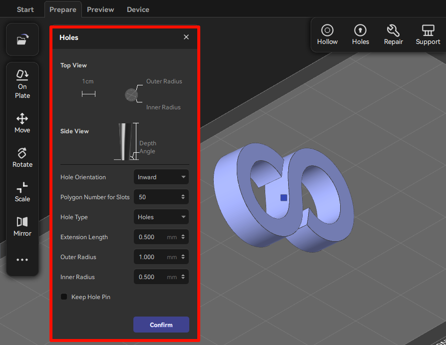
- Click the surface of the model to locate the positions of holes. Then, click "Confirm".
Repair (Ctrl+Alt+R)
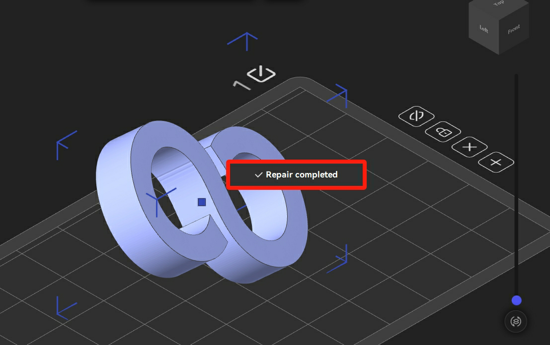
Users can click "Repair" and then the software will automatically fix any abnormalities of the model.
There will be a pop-up notification when a model with any abnormalities is imported.
Label (Shift+L)
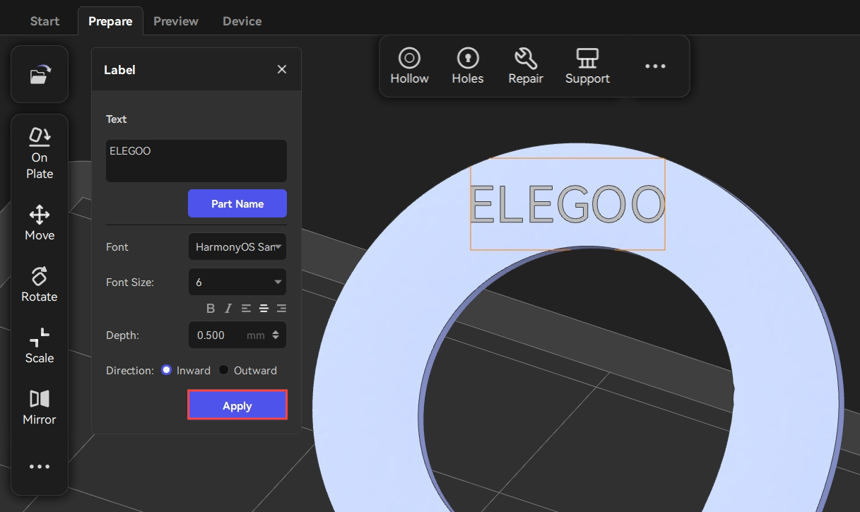
Users can add characters on the surface of a model by clicking "Label".
- Click "Label" and then type the text. Users can modify the "Font", "Font Size", "Depth", and "Direction" as needed.
- Inward: The label text is indented.
- Outward: The label text is embossed.
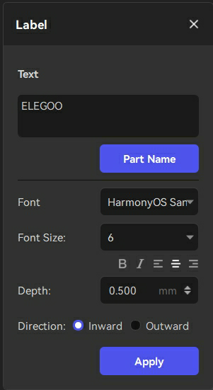
- Locate a region of the label on the surface to preview the text.
- After checking that the text is normal, users can click "Apply" to set the position of the label.
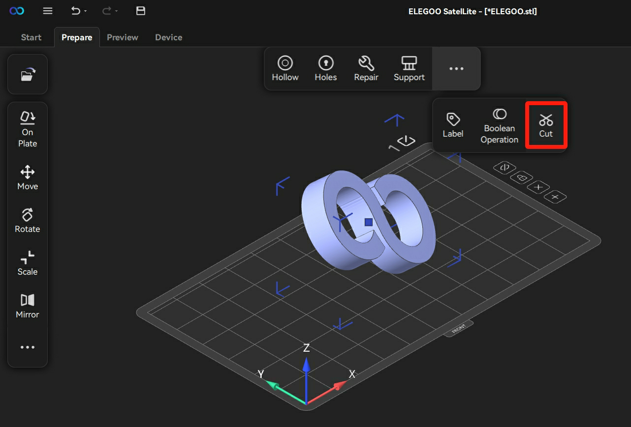
Cut (Alt+C)
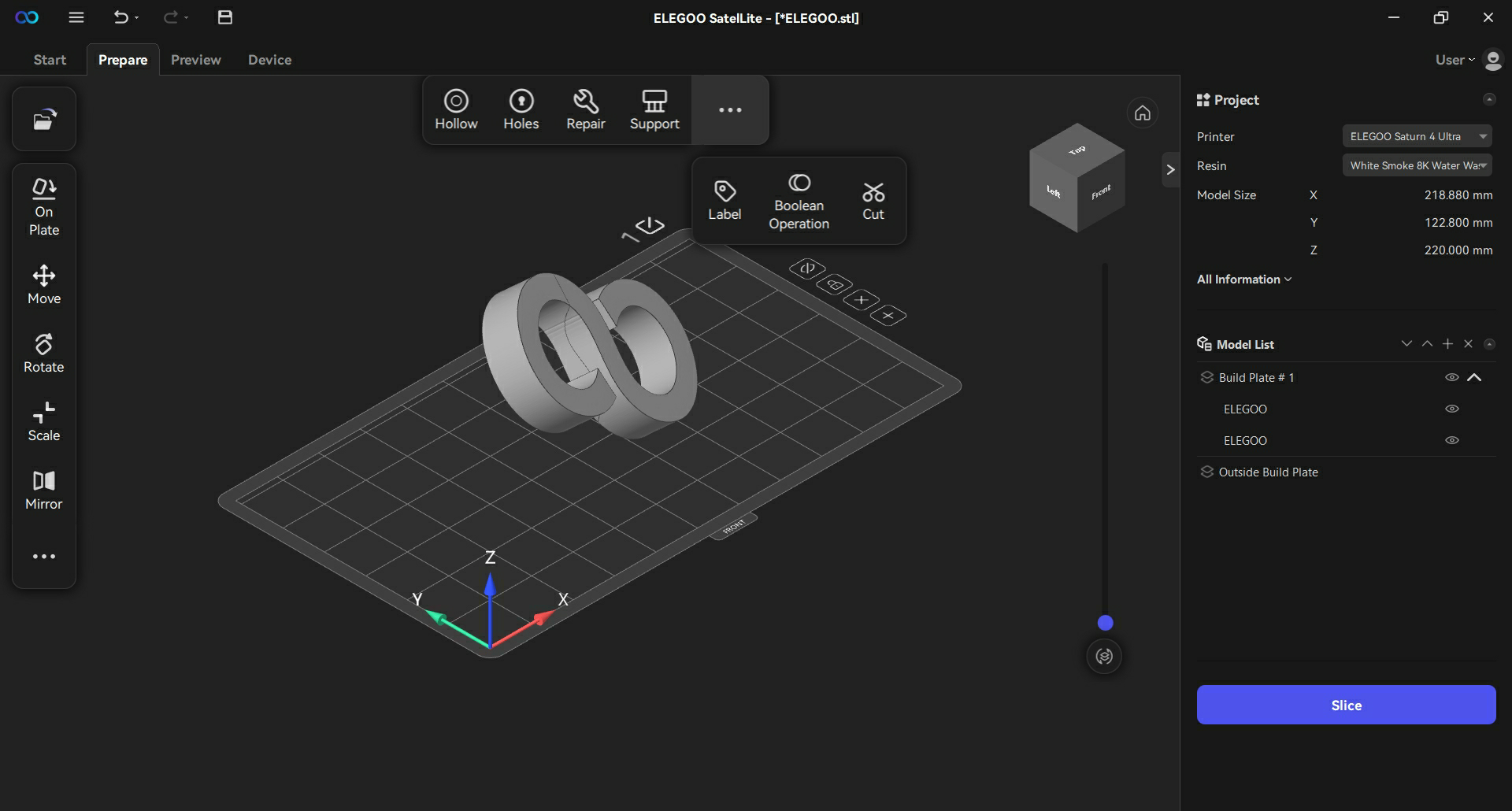
Users can divide a model into different parts by clicking "Cut".
- Click "Cut" and then click the position to cut on the surface of the model.
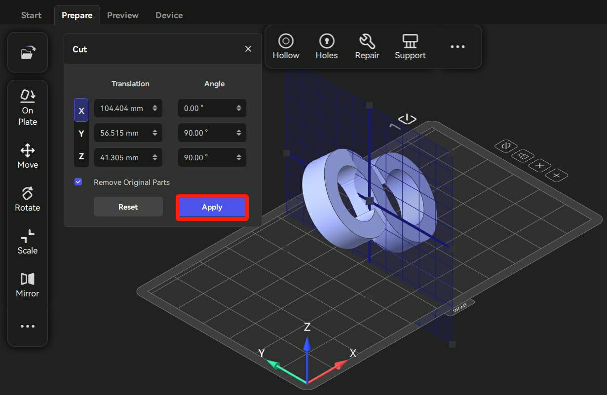
- Users can adjust the coordinates and modify the angle to optimize the cutting surface. Then, click "Apply" to confirm the modification of the model.
Boolean Operation (Ctrl+B)
Users can add, remove, and intersect two or more models to create a new model by clicking "Boolean Operation".
- Move models to appropriate positions.
- Select two or more models simultaneously and click "Boolean Operation" to select a type of operation.
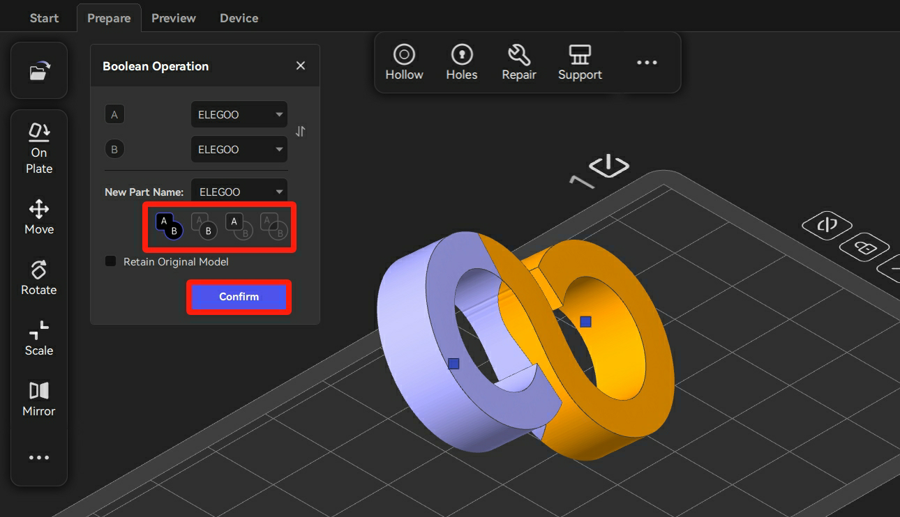
- A new model is created successfully.
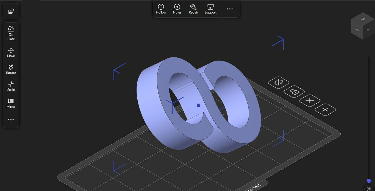
Boolean operation has four types of operation: Merge, A minus B, B minus A, and Intersect.
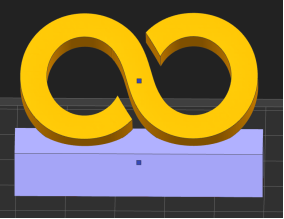
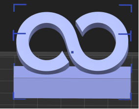
Merge: It means to combine two or more models to form a single one.
Before merging:
After merging:
A minus B: It means to subtract Model B contained in Model A.
Before A minus B:
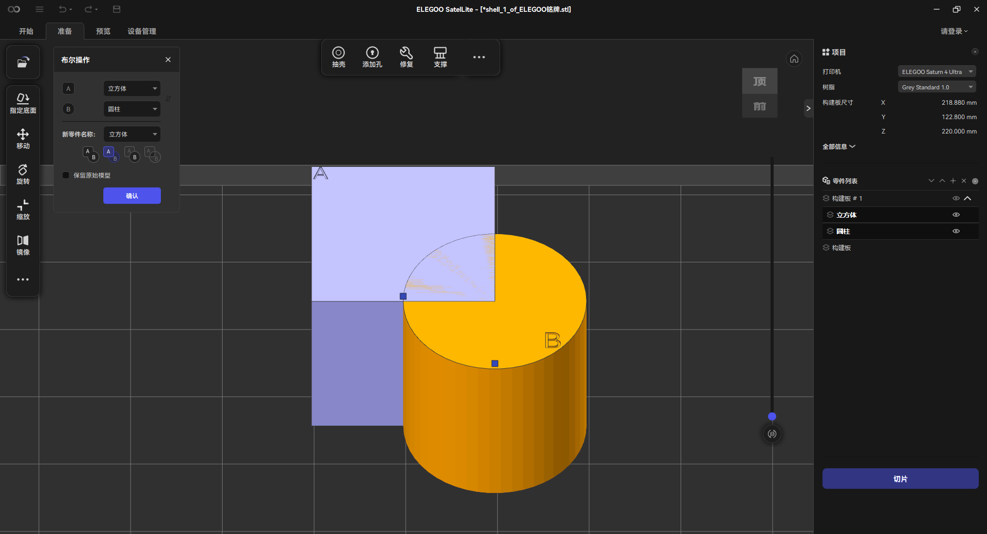
After A minus B:
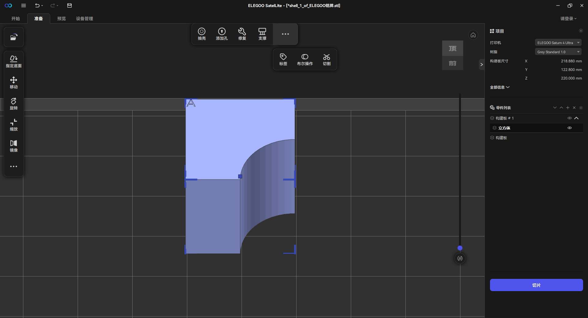
B minus A: It means to subtract Model A contained in Model B.
Before B minus A:
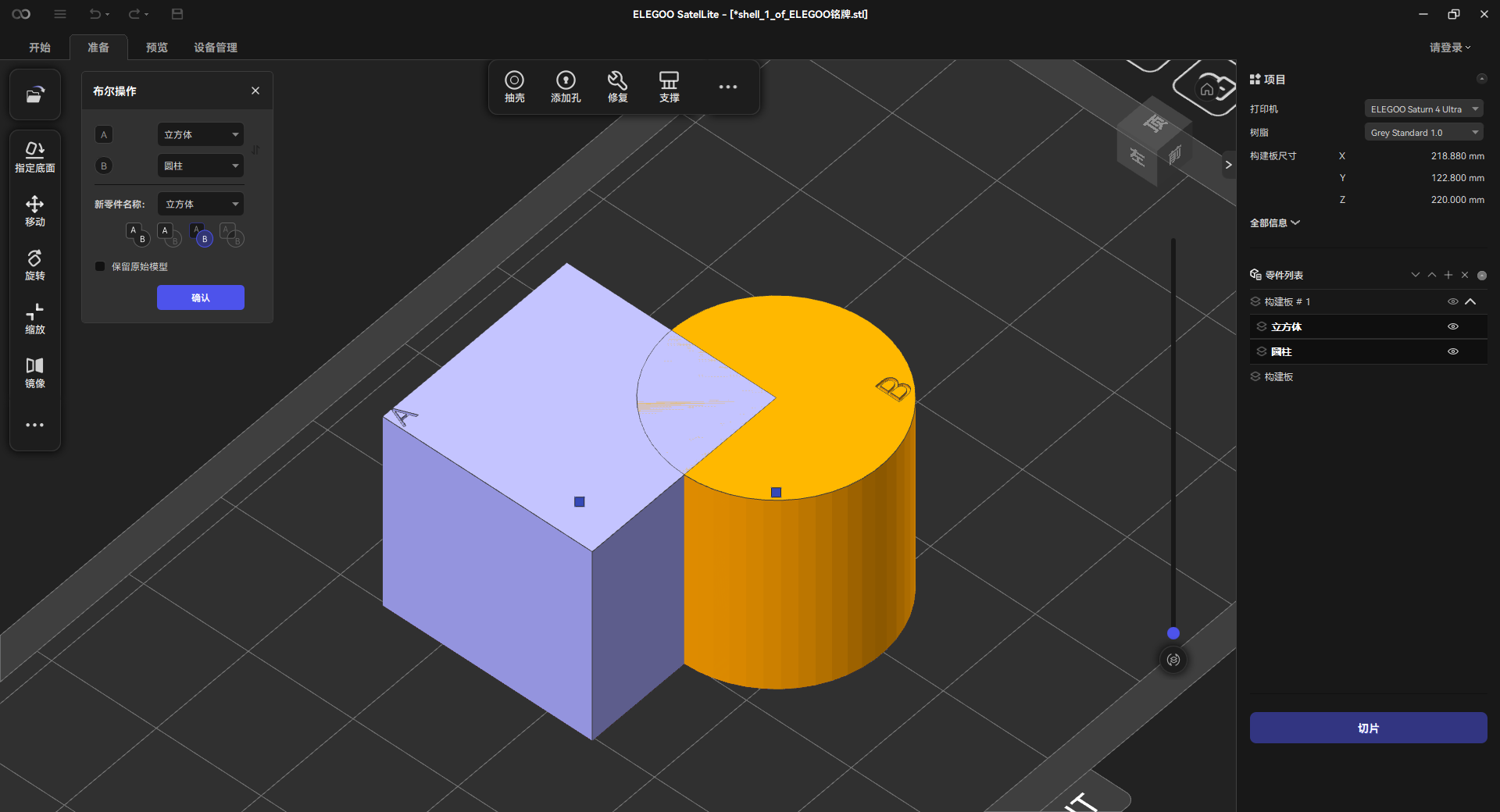
After B minus A:
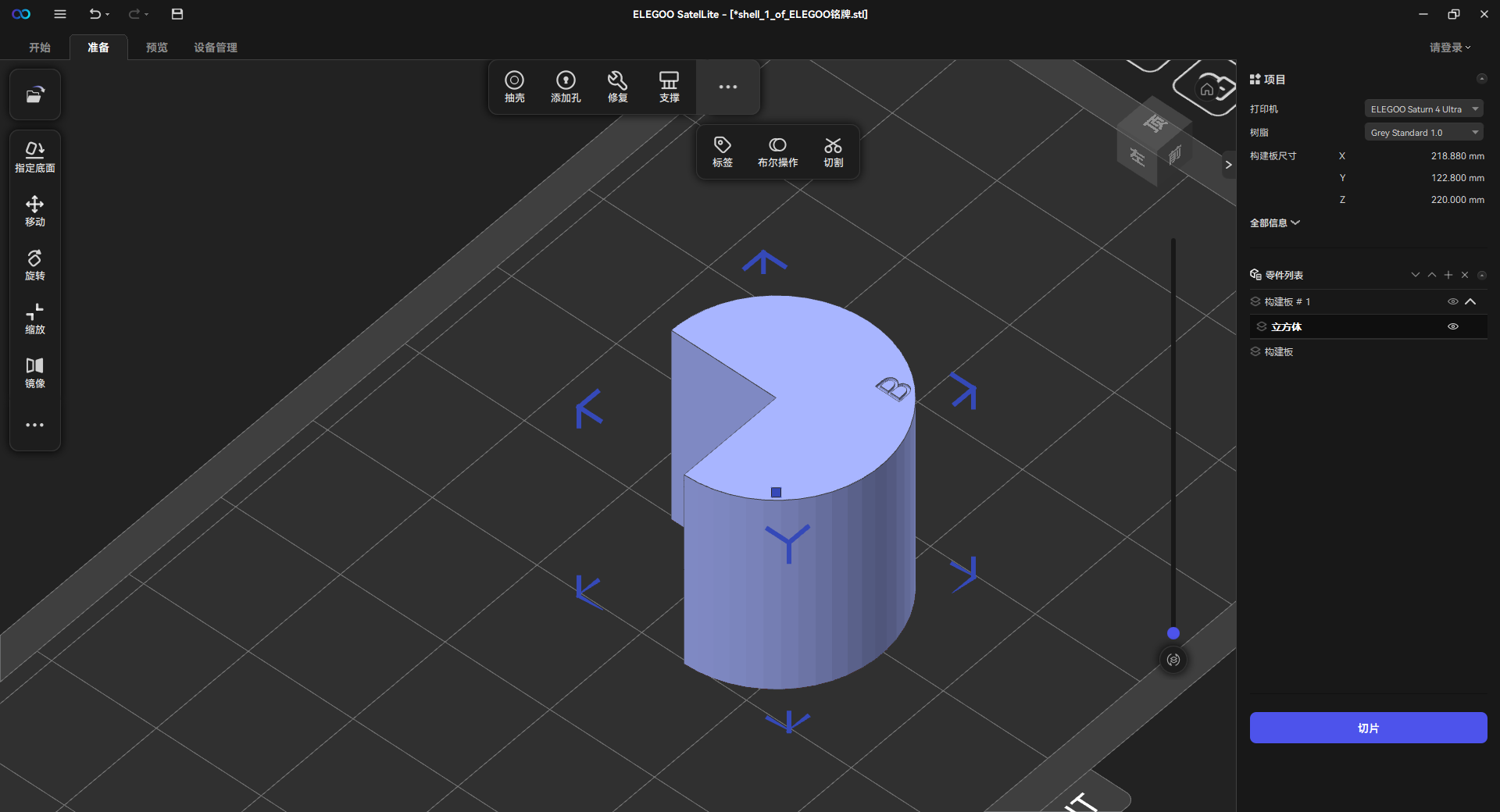
Intersect: It means to reserve the common part shared by Model A and B.
Before intersection:
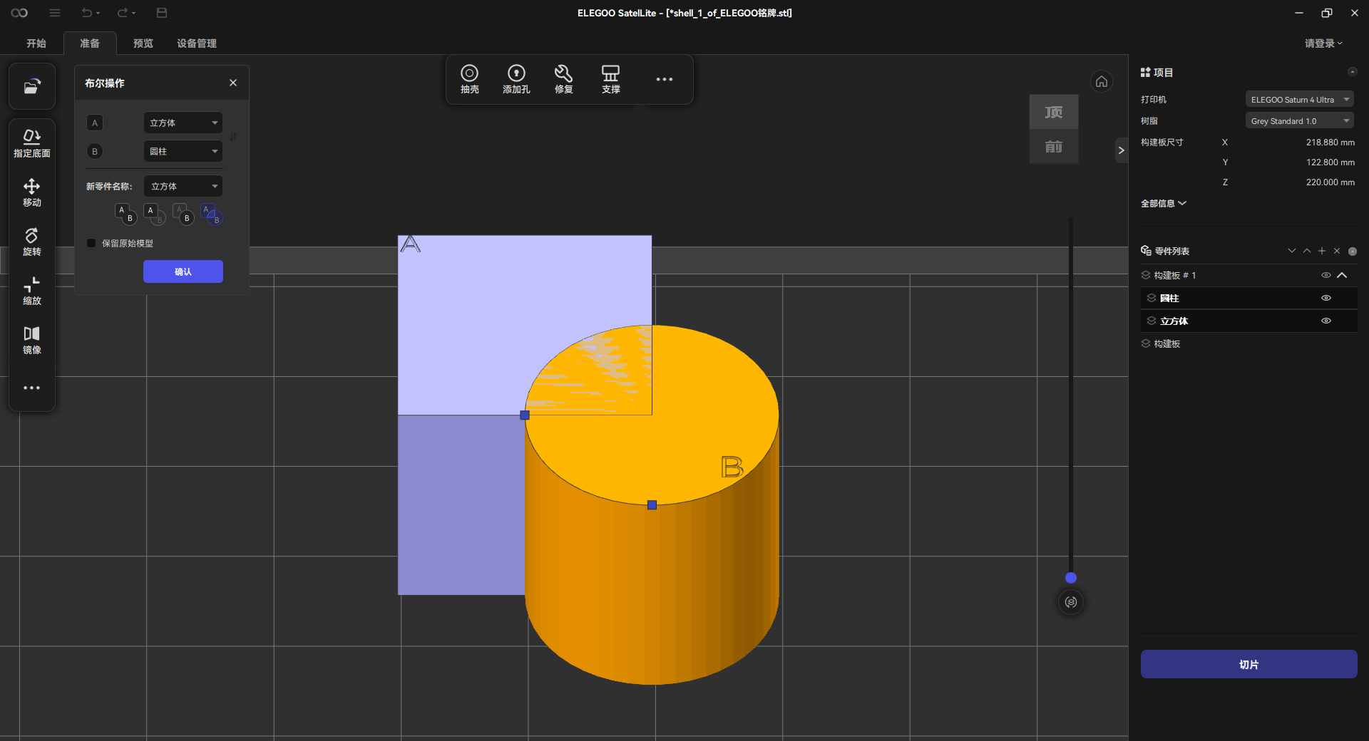
After intersection:
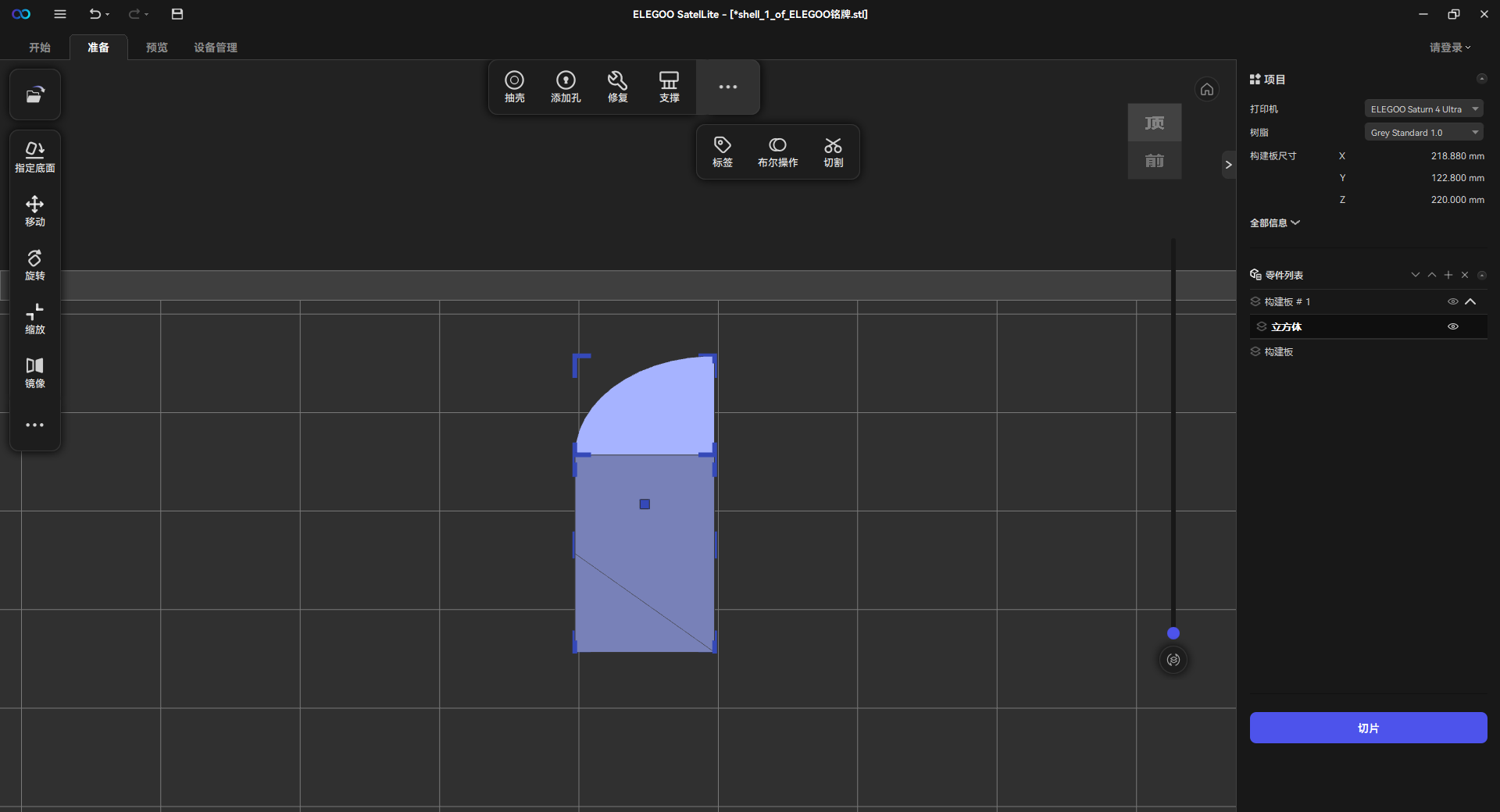
¶ 4.2.3 Support (Shift+I)
Users can follow the steps below to add supports to a model.
- Click "Support" to enter the support-adding interface. Then, the software can automatically identify the model's height and select the appropriate type of support.
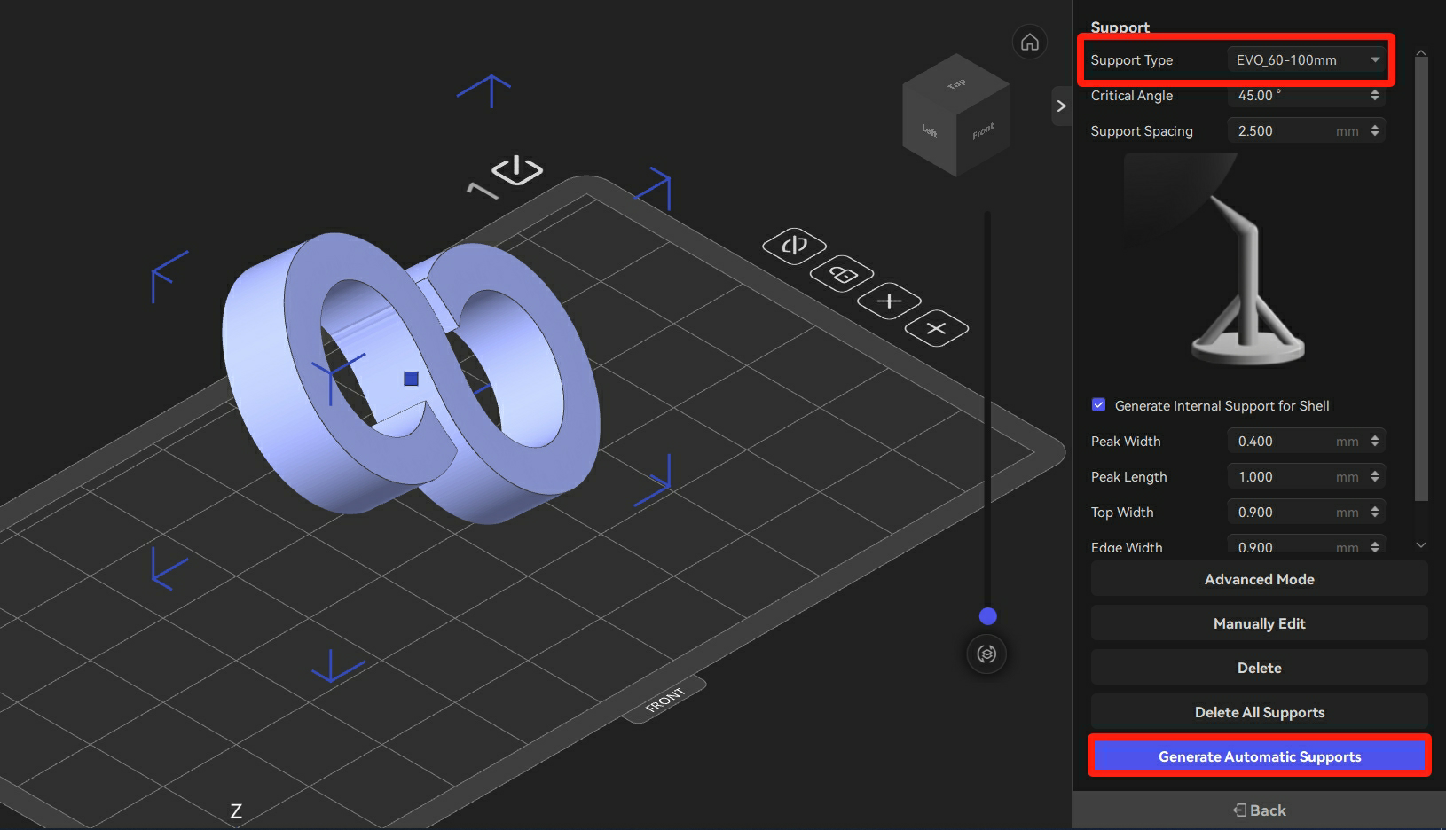
-
Click "Generate Automatic Supports", and the supports for the overhanging parts of the model can be generated automatically.
-
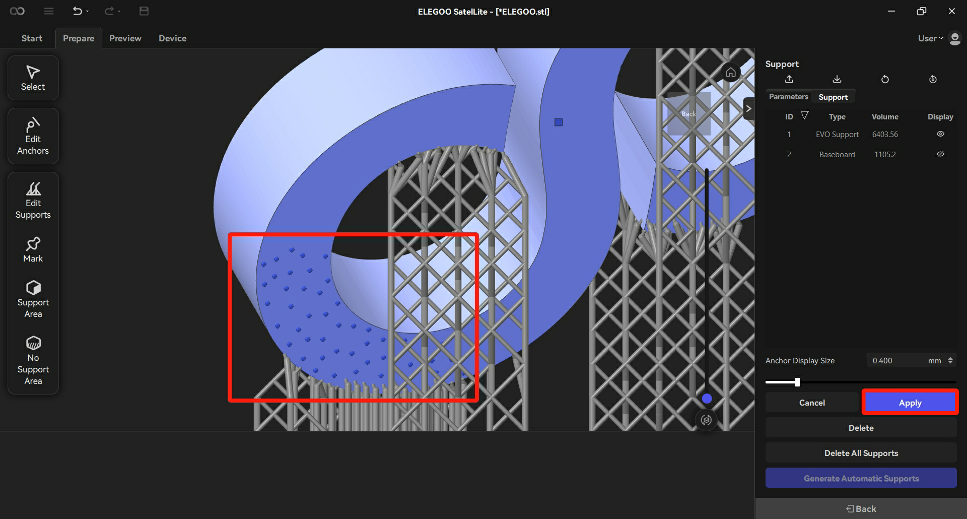
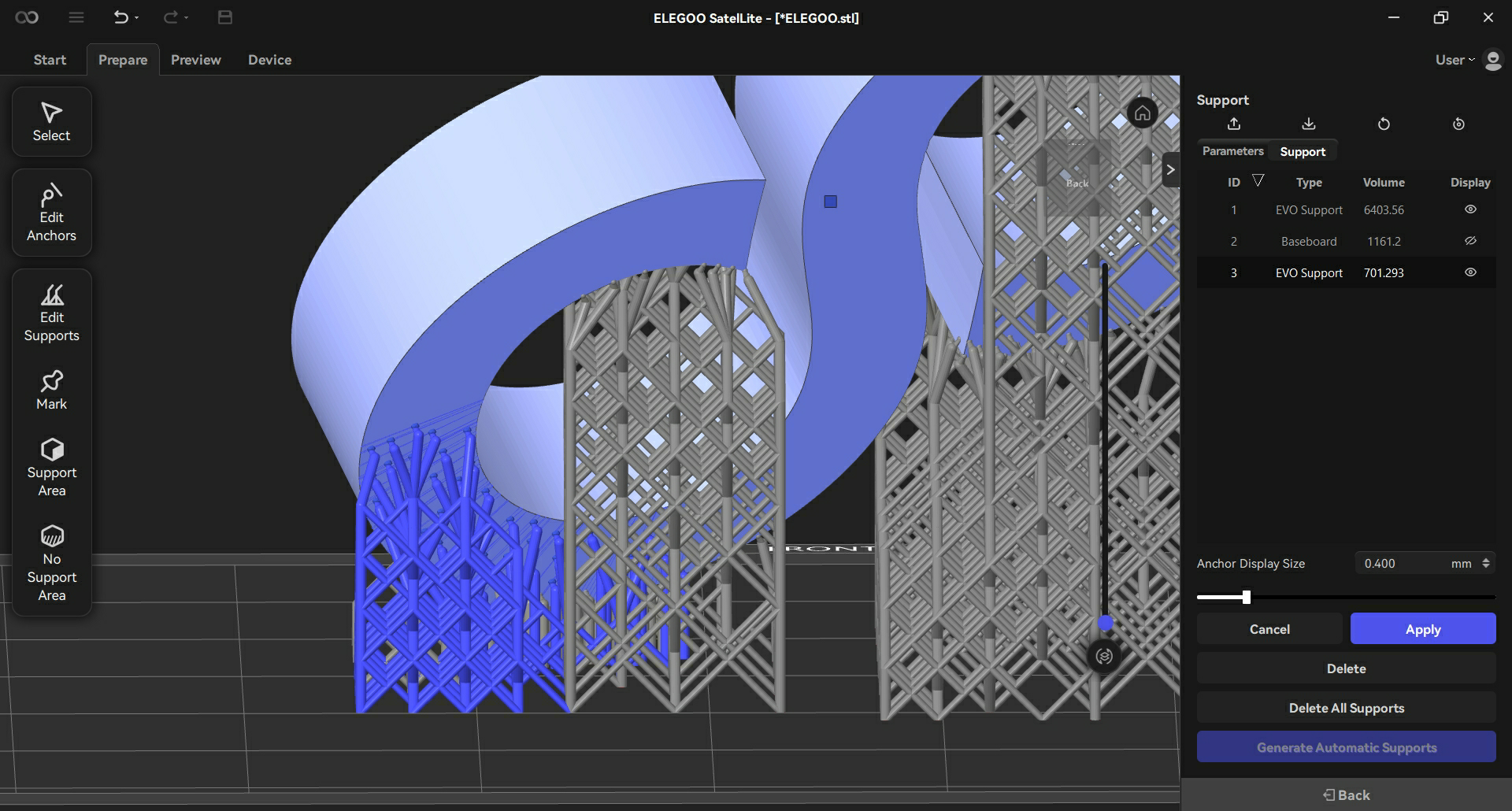
Rotate the model to observe the model and click "Manually Edit" to add supports manually to the positions where supports are not enough.
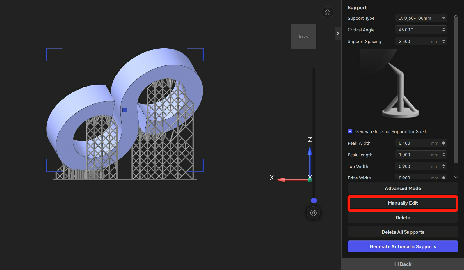
- Click the surface of the model and then click "Apply" to add the supports.
¶ 4.3 Slicing Models on Multiple Build Plates
ELEGOO SatelLite can create multiple build plates to process the models composed of several components.
¶ 4.3.1 Adding, Deleting, or Renaming a Build Plate
Adding a Build Plate
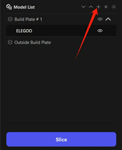
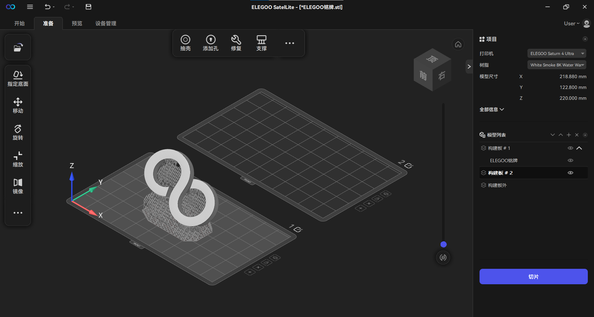
Method 1: Click "+" in the Model List on the right side of the interface to create a new build plate.
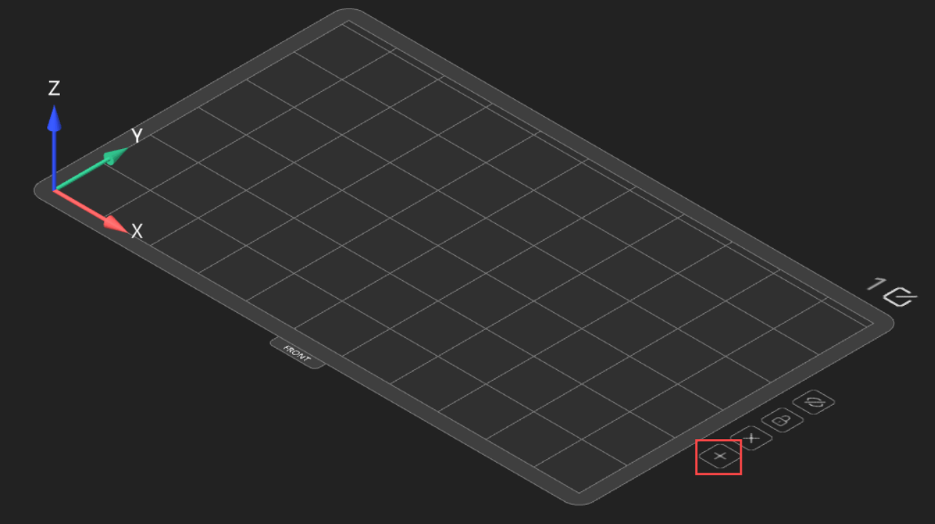
Method 2: Click "+" at the edge of the build plate to create a new one.
Deleting a Build Plate
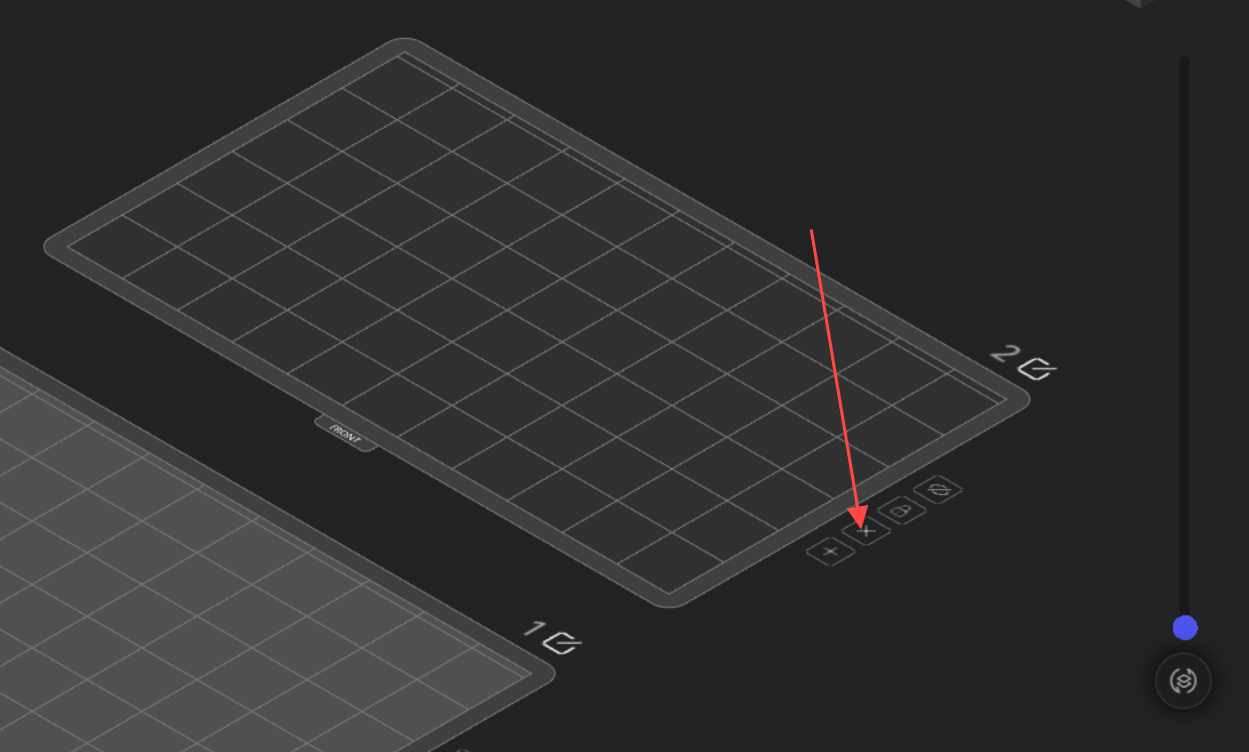
Method 1: Click "╳" at the edge of the build plate to remove the unnecessary build plate.
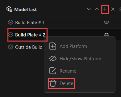
Method 2: Select the build plate to delete from the Model List at the right side of the interface, and then right-click it or click "╳" to delete.
Renaming a Build Plate
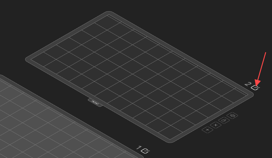
Method 1: Click the Edit icon at the edge of the board to rename the board.
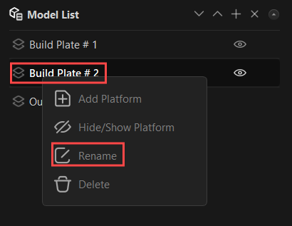
Method 2: Select the build plate to be renamed in the Model List at the right side of the interface, and then right-click it to rename it.
¶ 4.3.2 Slicing Models on Multiple Build Plates
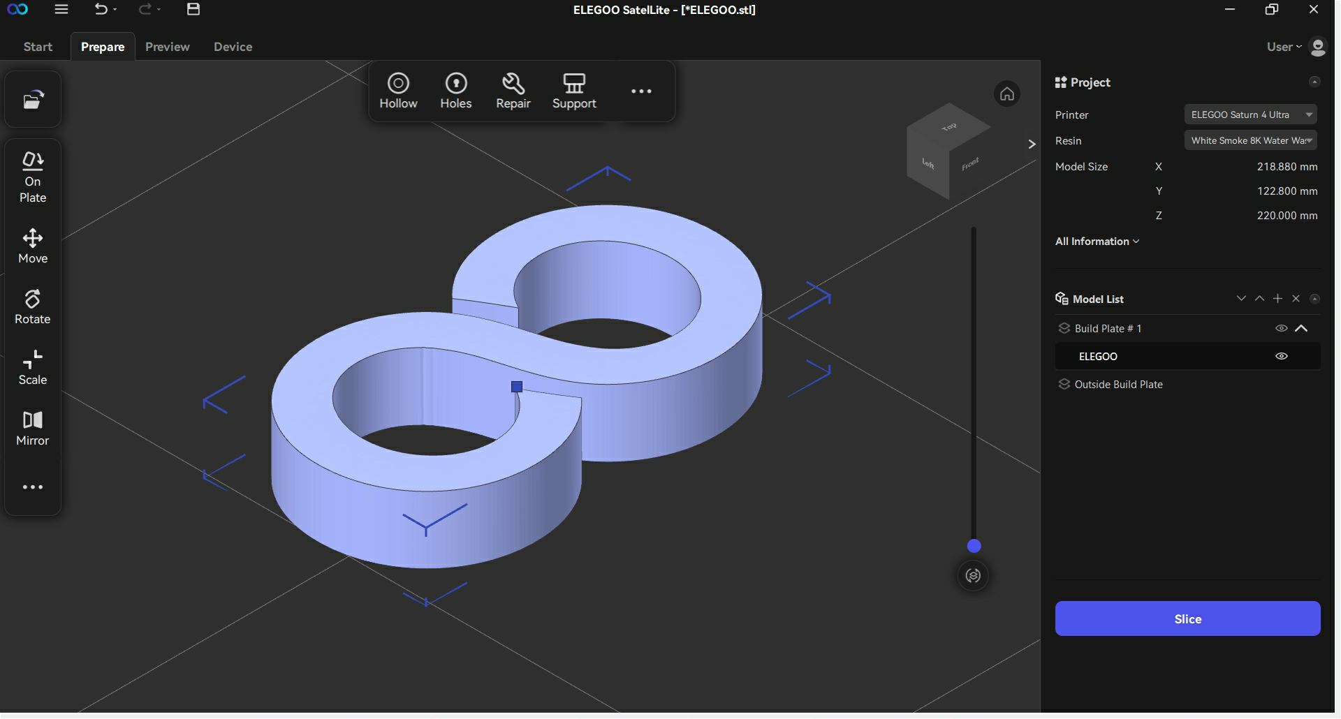
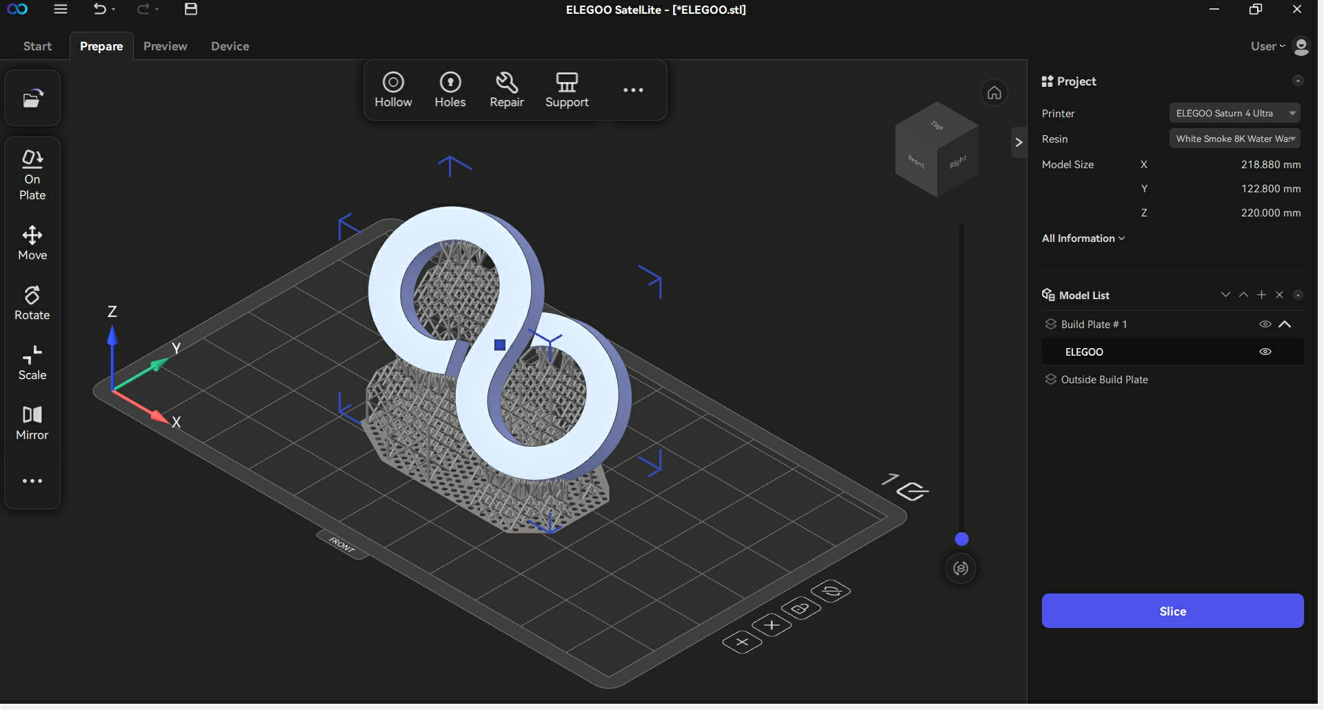
Follow the steps below to import and slice models on multiple build plates.
- Import a model.
- Process the model by rotating, hollowing, and adding supports and holes.
- Click "+" in the Model List at the right side of the interface, or click "+" at the edge of the build plate to create a new build plate.
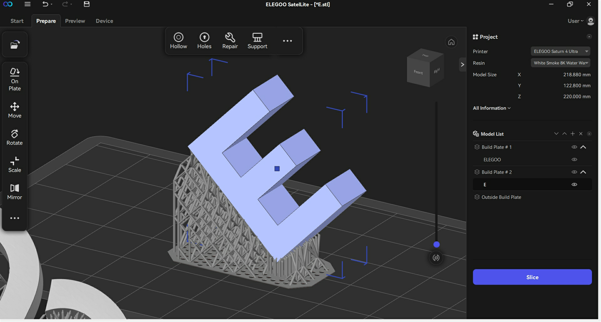
- Add a new model on the newly created build plate and then process the model by rotating, hollowing, and adding supports and holes as needed.
- After processing the model, select one of the build plates and click "Slice - Save Sliced File".
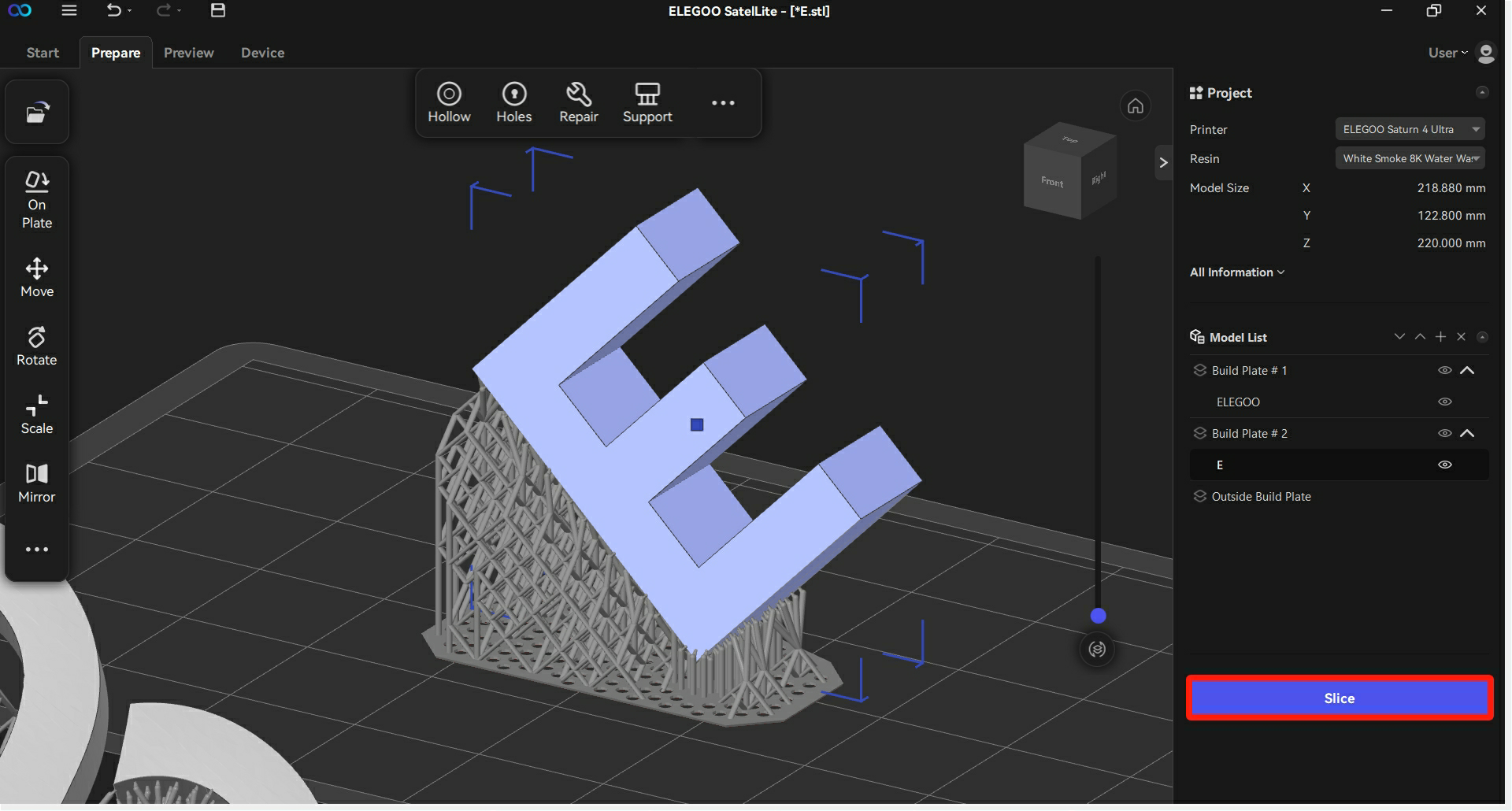
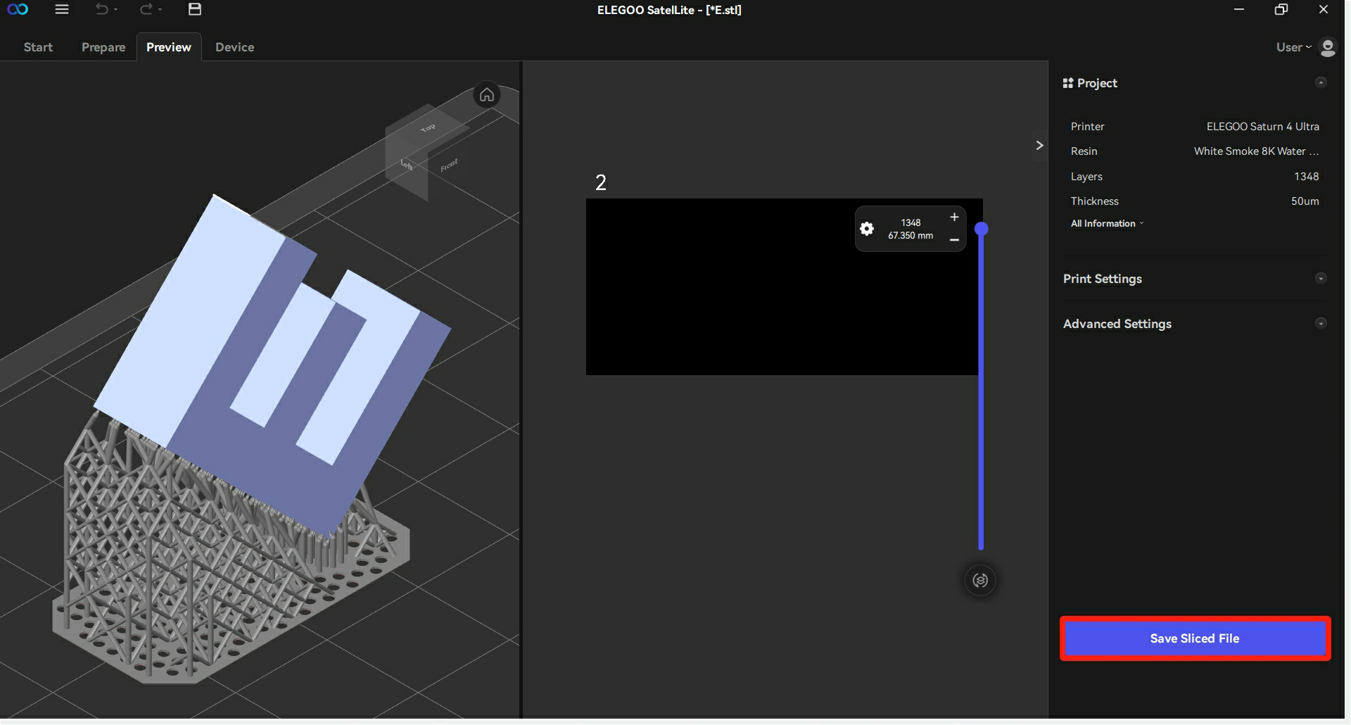
- Choose the export format, revise the folder and file names of the saved model, and then click "Confirm" to save the file.
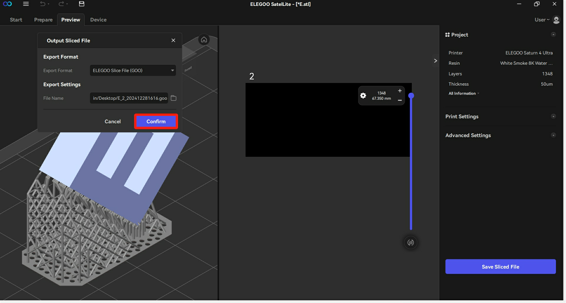
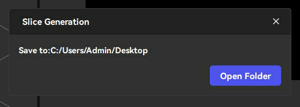
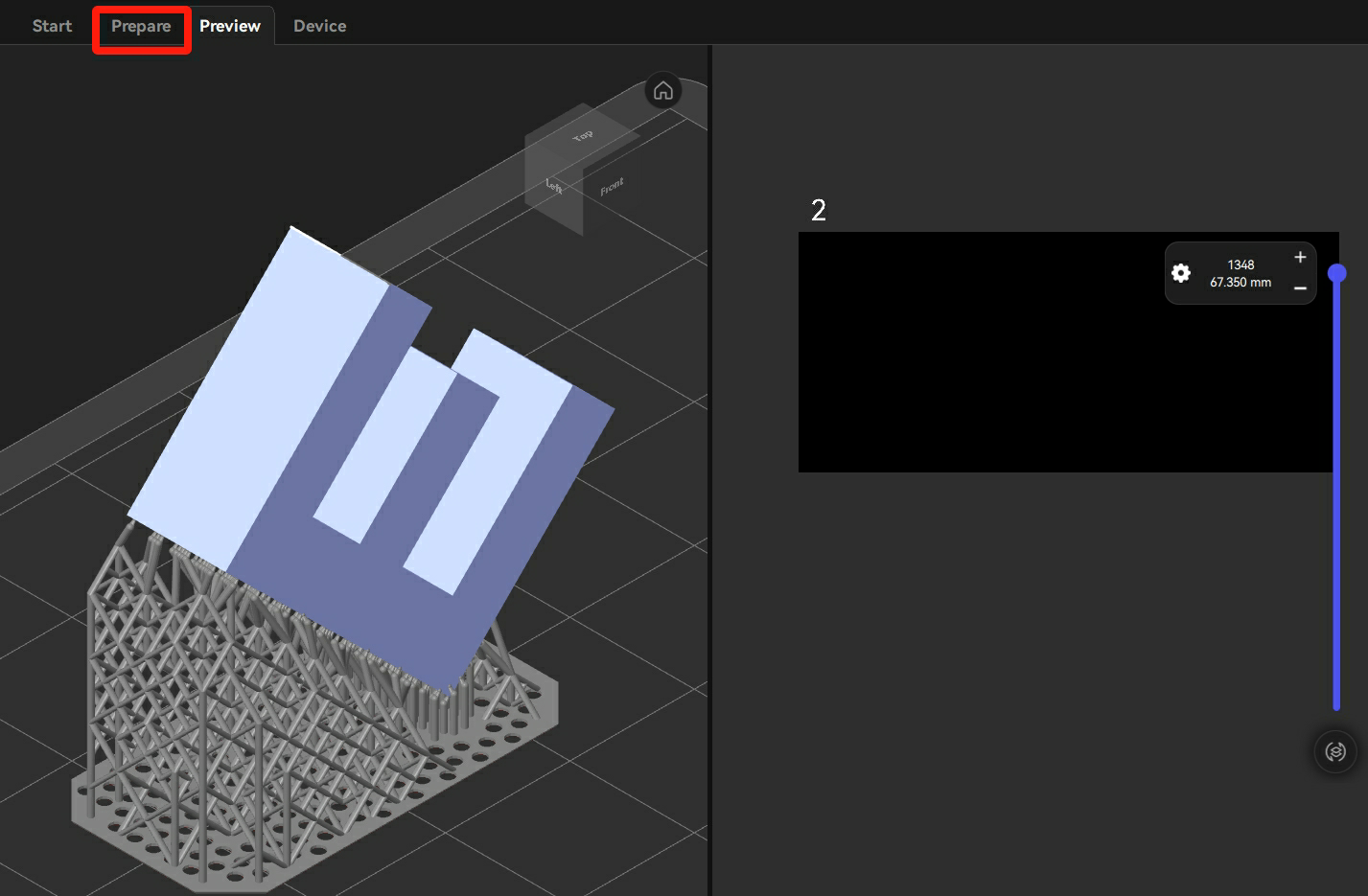
- Click "Prepare" to return to the main interface.
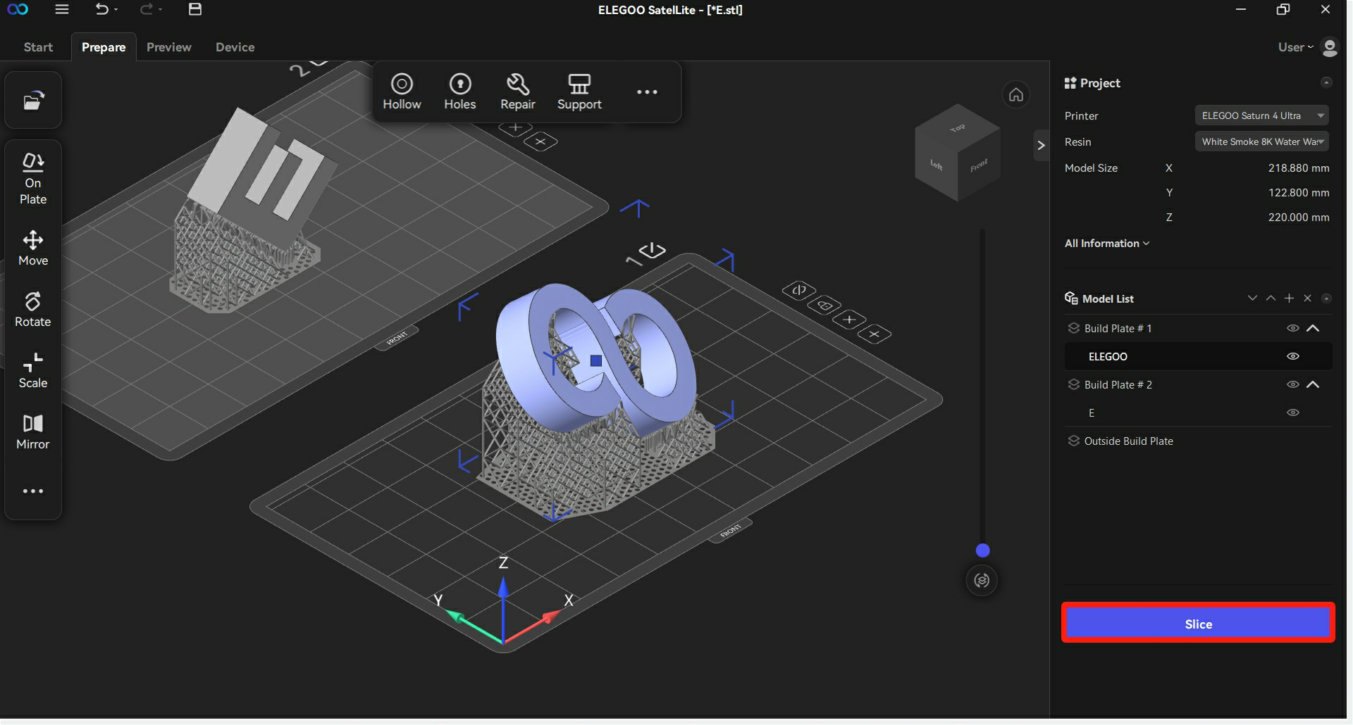
- Select the other build plate and then click "Slice".
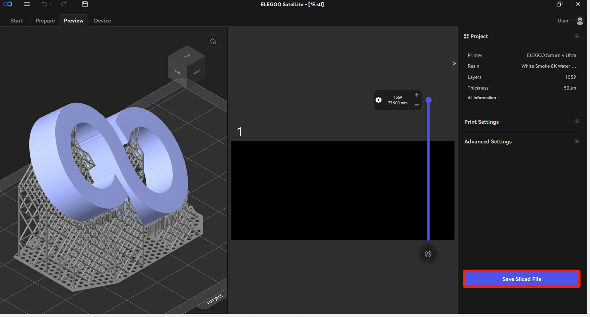
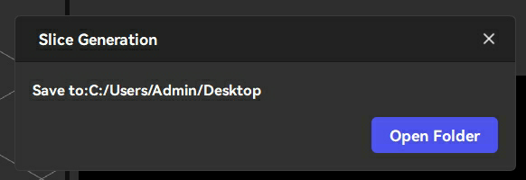
- Click "Save Sliced File" to save the file.
¶ 4.3.3 Saving Models on Multiple Build Plates as a Single Project File
Follow the steps below to save the models on multiple build plates as a single project file.
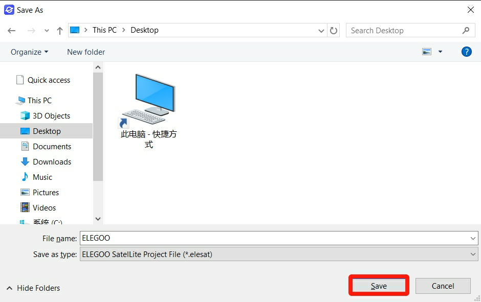
- Click the "Save as" icon located in the top corner of the interface.

- After revising the file, click "Save" to store the project file.
¶ 4.4 Slicing and Parameters Setting
¶ 4.4.1 Slicing
Users can slice the model after adding supports to it.
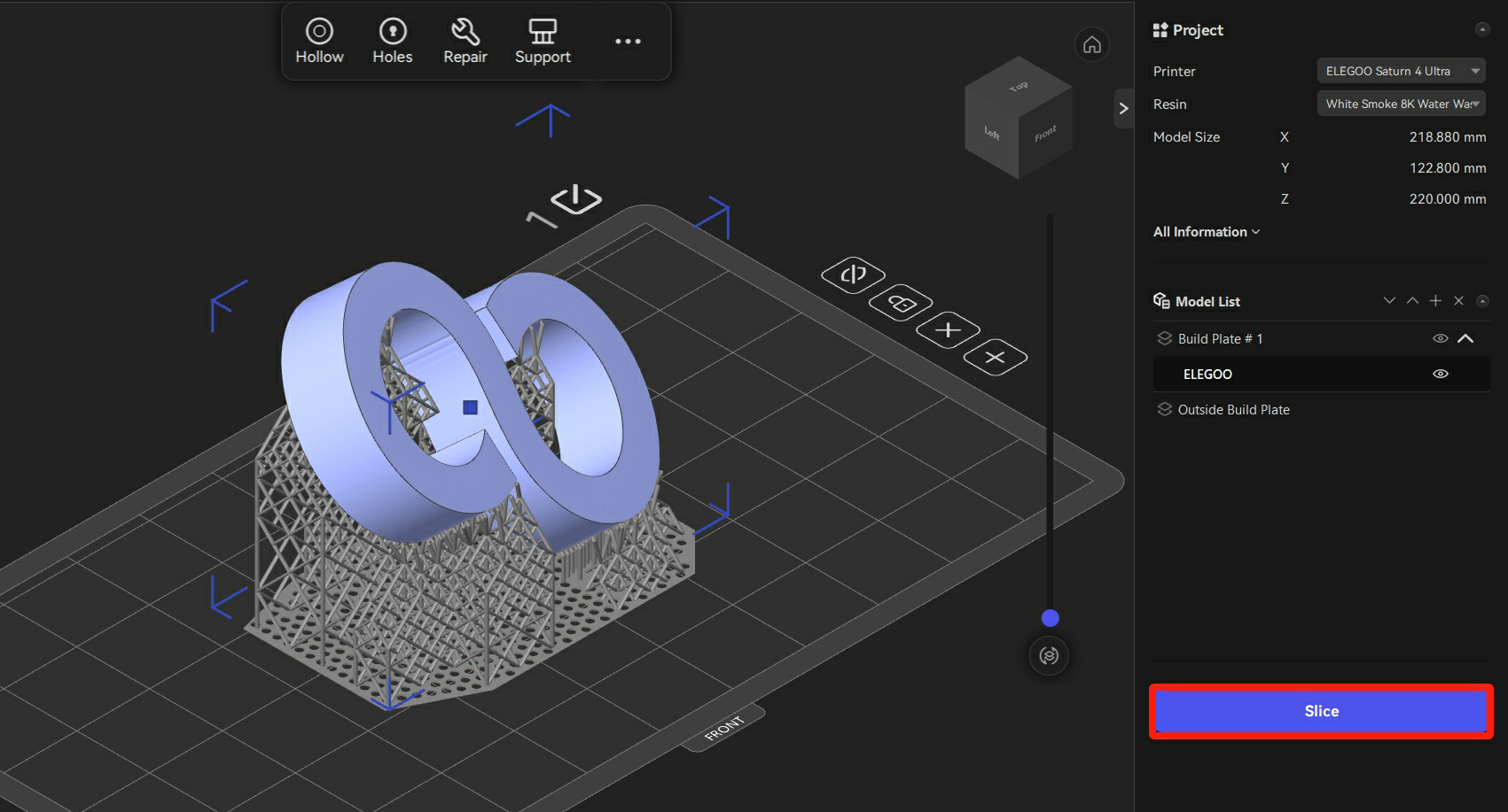
- In Prepare interface, click "Slice".
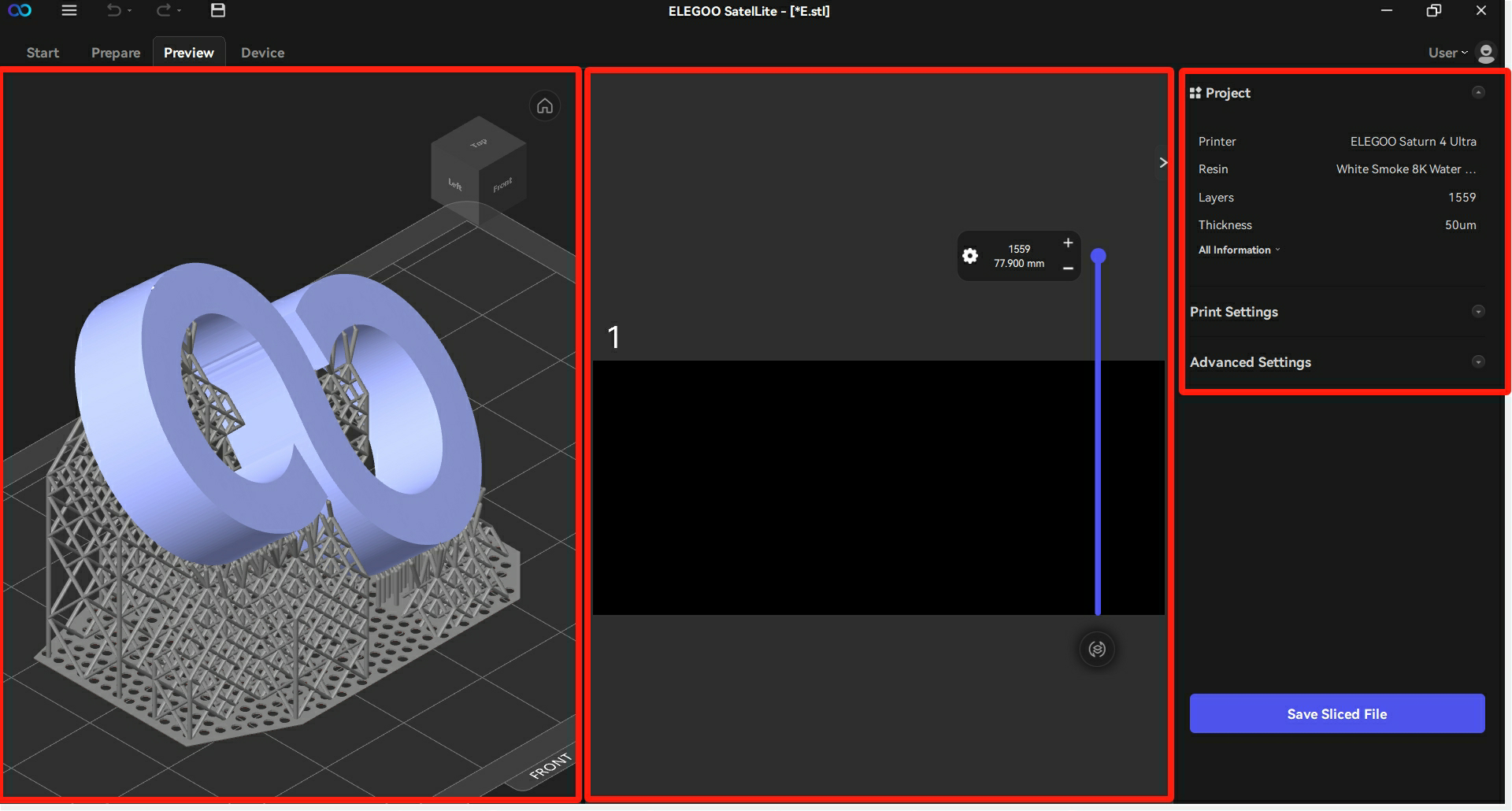
- The left side of the Preview interface shows the cross-section of the 3D model; the middle shows the bird's-eye view of the cross-section; the right side shows the project information.
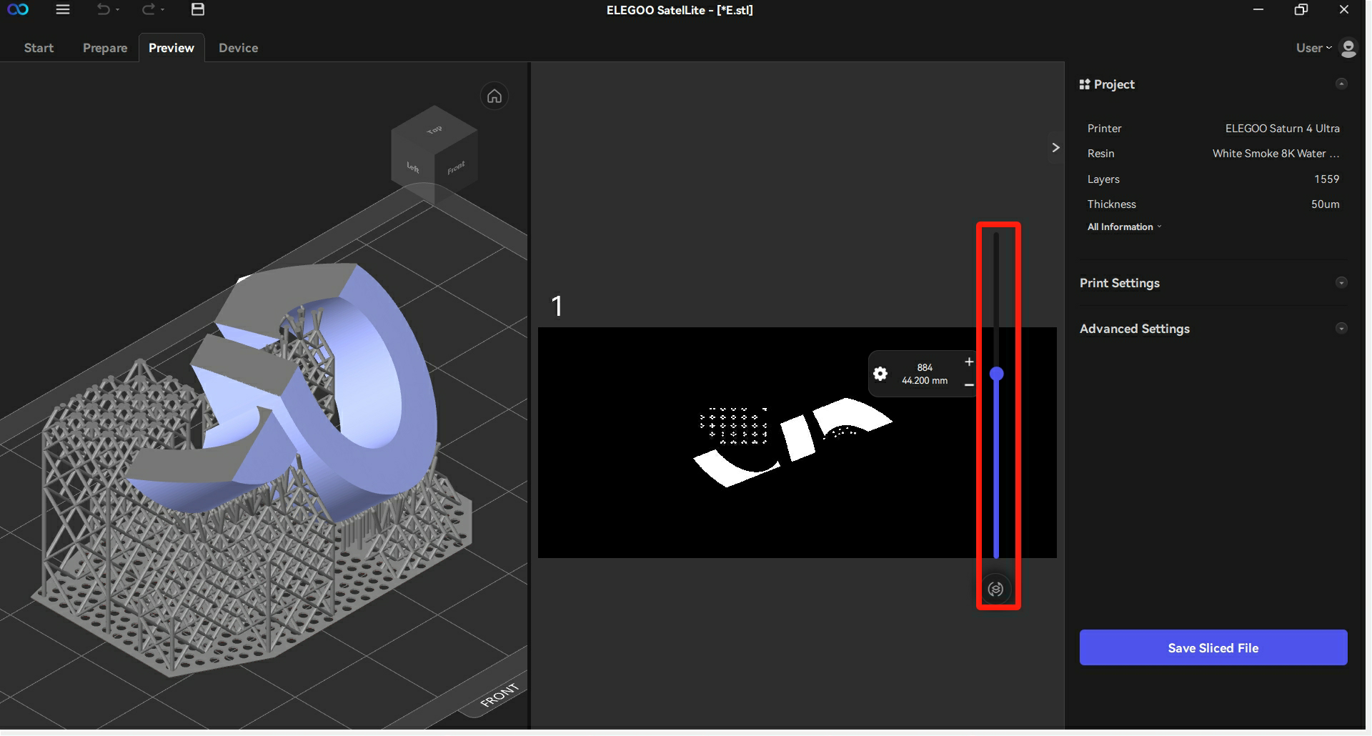
- Users can drag the process bar in the middle of the interface to preview the cross-section at each height.
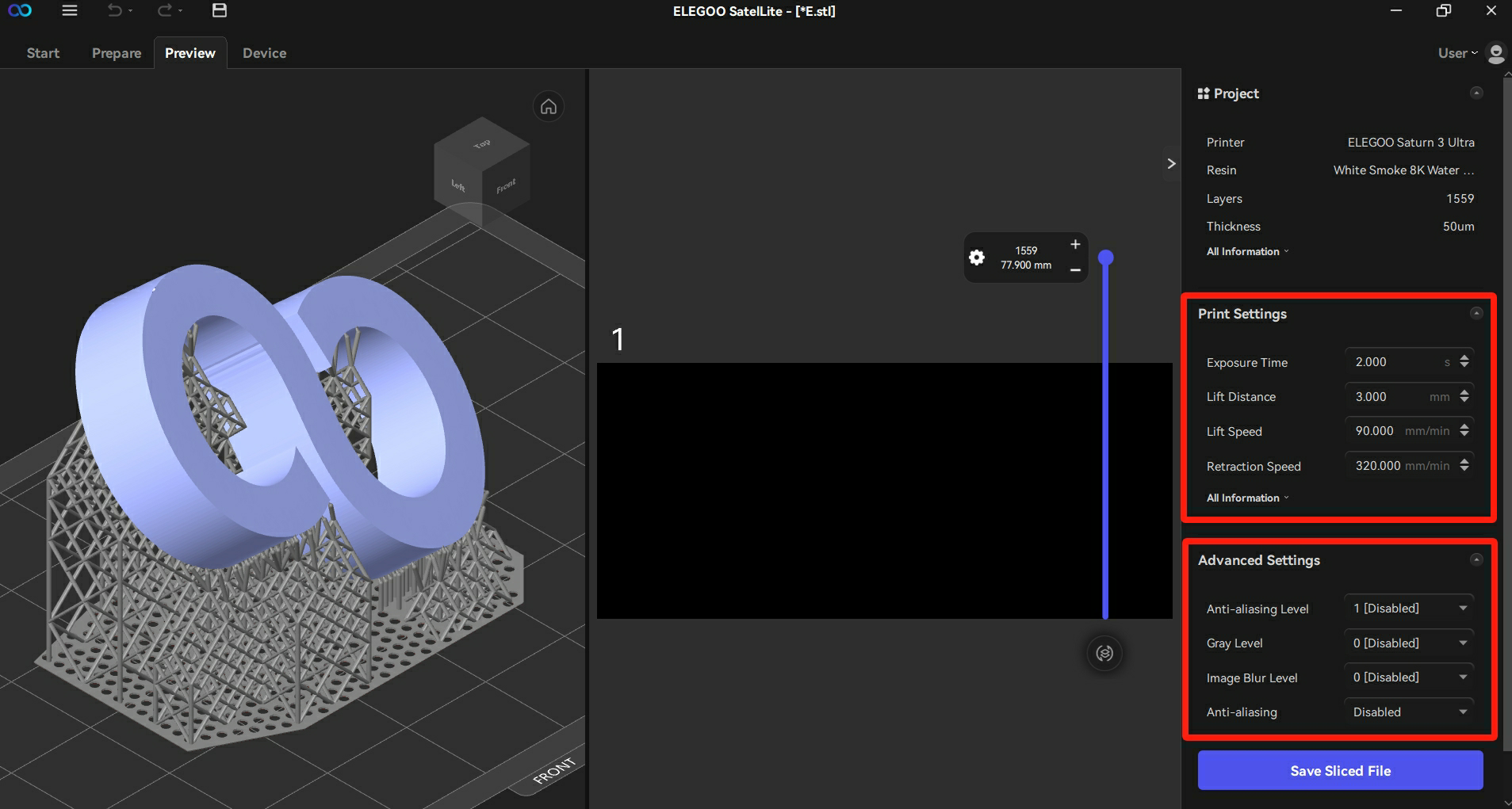
¶ 4.4.2 Setting Parameters After Slicing
As shown in the figure below, users can modify some printing parameters at the right side of the interface.
¶ 4.5 Exporting Sliced Files
¶ 4.5.1 Exporting *.goo Files
Follow the steps below to save the sliced model as a printable file.
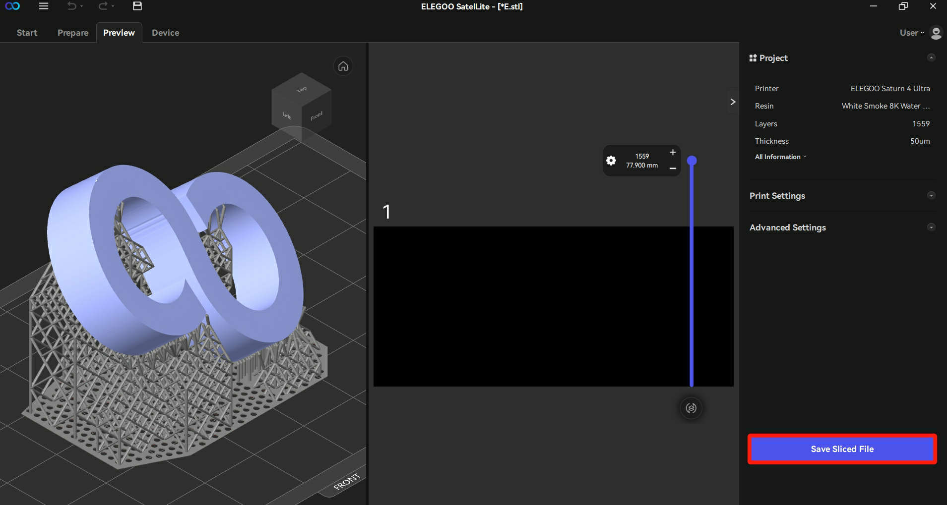
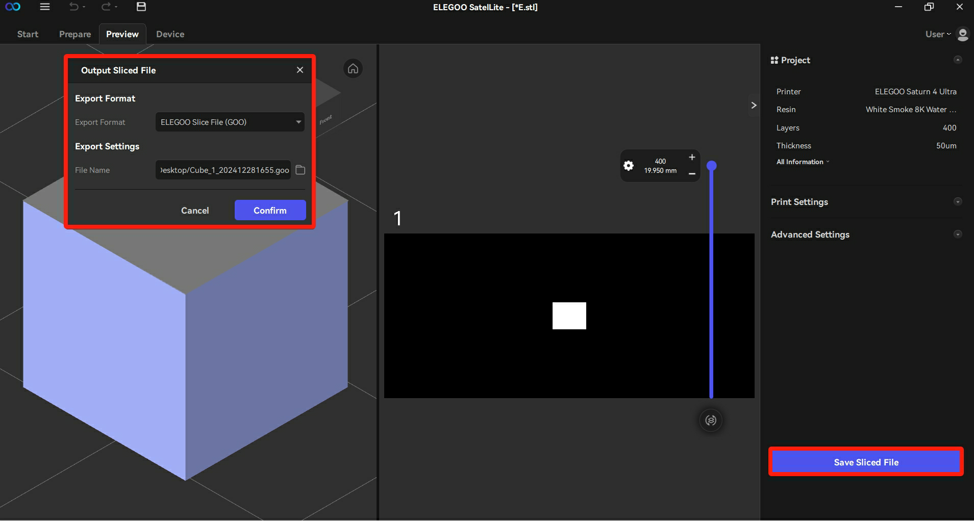
- Click "Save Sliced File" in the Preview interface.
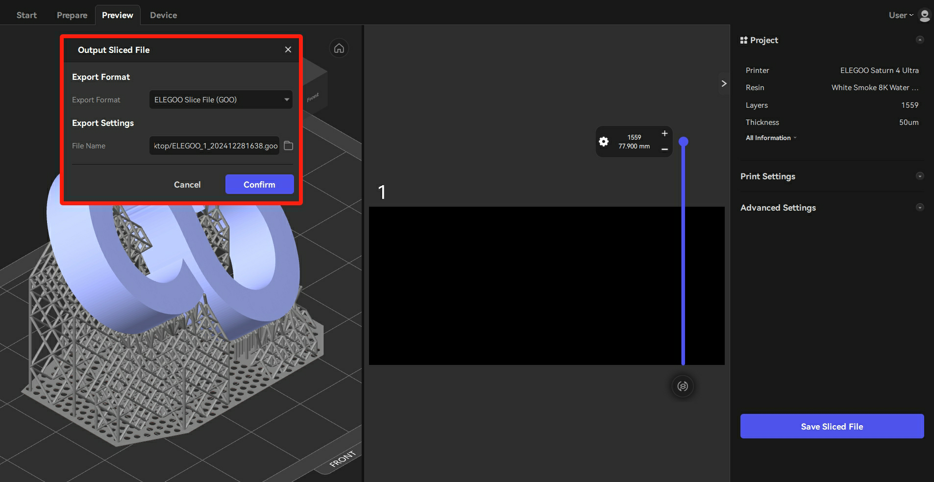
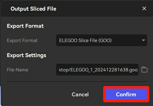
2. In the Output Sliced File pop-up window at the top left corner, users can set the export format and the file name.
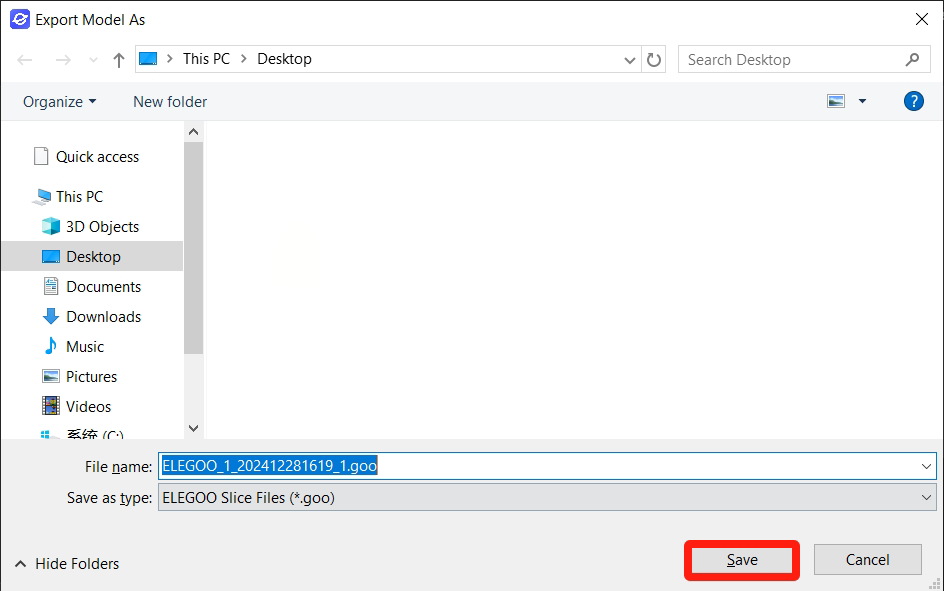
- Choose ELEGOO Slice Files (GOO) as the export format. Click the file icon behind the file name to set the location and name of the printable file. Then click "Save".
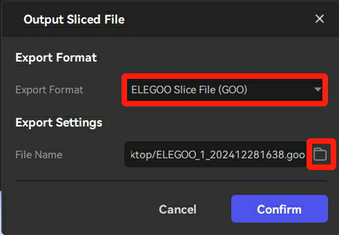
- After choosing the export format, file name, as well as the file's location, click "Confirm" to save the file.
¶ 4.5.2 Exporting Different Sliced File Format
As a format conversion plug-in, UVtools supports the ELEGOO SatelLite, allowing users to export various sliced file formats that are compatible with a wider range of printer types.
This article introduces how the UVtools plug-in integrates with ELEGOO SatelLite to export various file formats.
Note: ELEGOO SatelLite can only export *.goo files without the use of the UVtools plug-in.
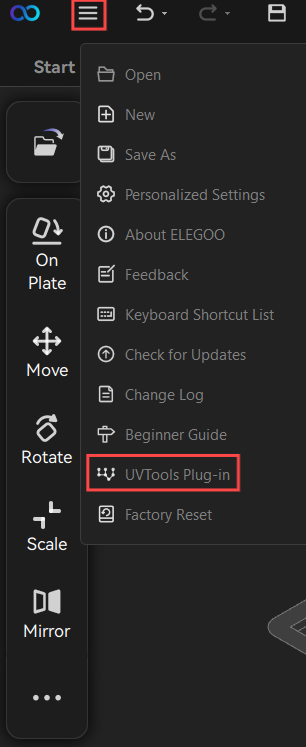
- Click the main menu button and then click "UVTools plug-in".
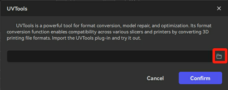
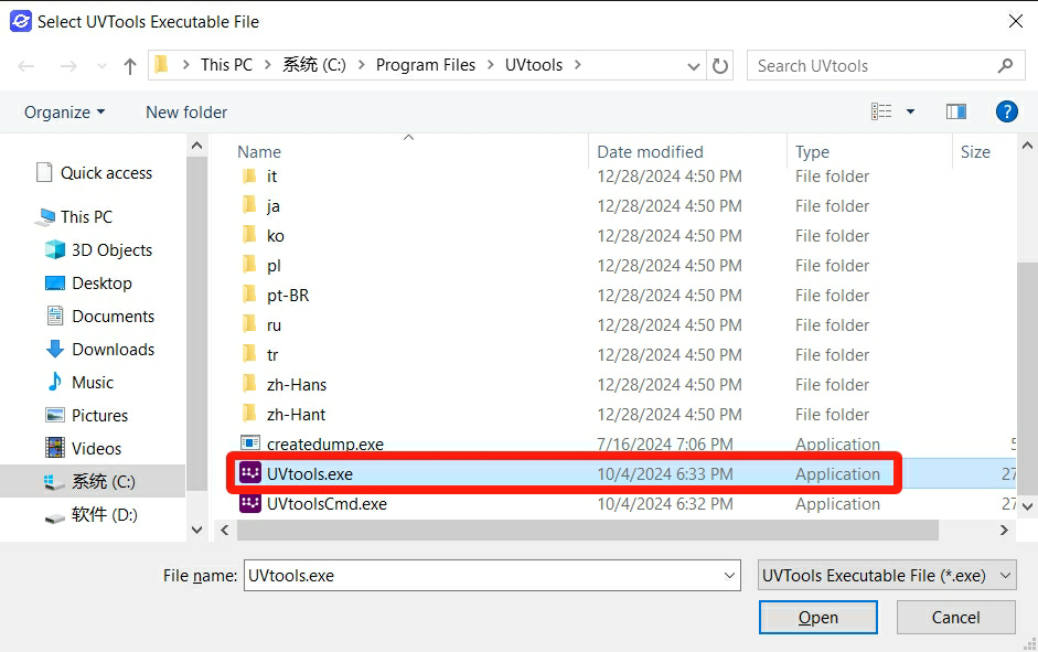
- Click the folder icon.
- Click the "UVtools.exe" file and then click "Open".
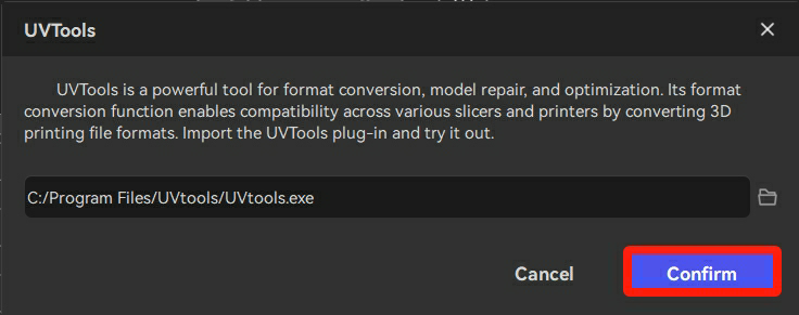
- Click "Confirm", and then the UVTools plug-in is set up.
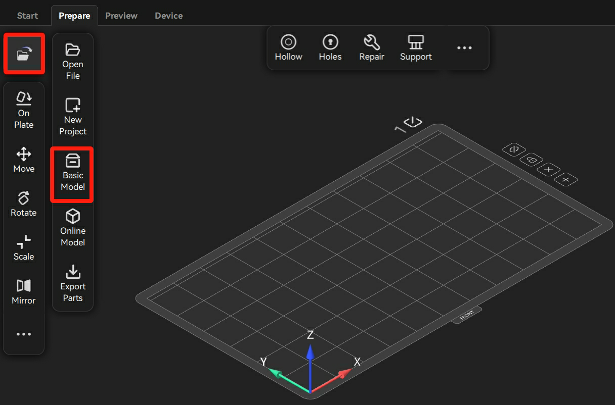
- Click "File - Basic Model" to create a model.
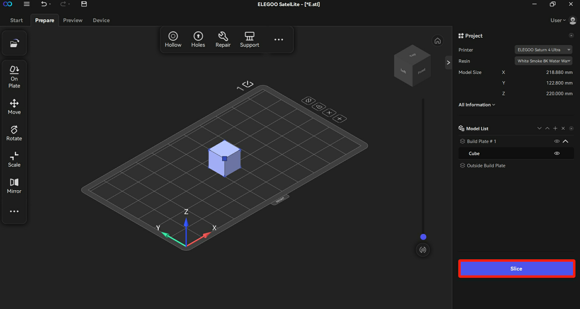
- Click "Slice".
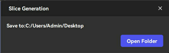
- Click "Save Sliced File" and the Output Sliced File pop-up window appears at the top corner of the interface.
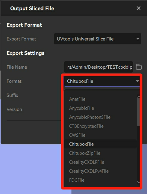
- Change the export format to "UVtools Universal Slice File".

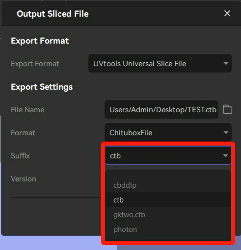
- This tutorial takes ChituboxFile file and
*.ctbsuffix as examples.
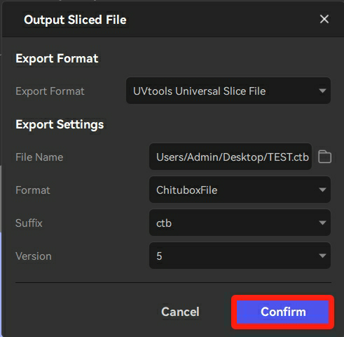
- Click "Confirm" to save the file.
- The file can be saved successfully.
¶ 5. FAQ
How can I find help when using ELEGOO SatelLite?
- When you first open ELEGOO SatelLite, a step-by-step tutorial will guide you through the basics. If you’d like to revisit the beginner’s guide, you can find it in the menu.
- If you’re unsure about the meaning of a specific term in the toolbar, simply hover your mouse over it, and a pop-up explanation will appear.
- For guidance on specific operations, such as installing UVtools, visit the ELEGOO YouTube channel for detailed video tutorials.
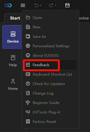
- If none of the above resolves your issue, please send us feedback through the feedback option in the menu.
Why can't I install ELEGOO SatelLite due to a missing graphics driver?
Reason 1: Your computer may lack a dedicated graphics card.
Reason 2: The graphics driver of your computer could be missing.
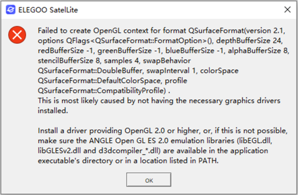
Handling Procedure:
- Refer to 1. Introduction to ELEGOO SatelLite to check the software's minimum system requirements.
- Refer to 2. Installation to reinstall the driver and attempt to install ELEGOO SatelLite again.
Does SatelLite support imperial units?
Yes, users can switch between millimeters (mm) and inches in the personalized settings.
How can I contact the ELEGOO SatelLite team?
You can send us feedback through the feedback option in the menu.
How many build plates can I have in a single project?
You can use up to 16 build plates simultaneously in a single project.
Why do I need supports in resin printing?
Supports are essential for resin printing to:
- Prevent overhangs from sagging or failing.
- Anchor parts of the model that are not connected to the build plate.
- Reduce suction forces during printing.
What is the Resin Library in ELEGOO SatelLite?
The Official Resin Library offers official ELEGOO resin settings and also allows users to modify or create custom settings in their personal library. Please note that a login is required to access your personal Resin Library.
Why does it prompt "Account already exists" or "Incorrect password" when I register or log in?
Reason: You may register on the website using Facebook or Google, with no password set.
Handling Method: Set a new password manually.
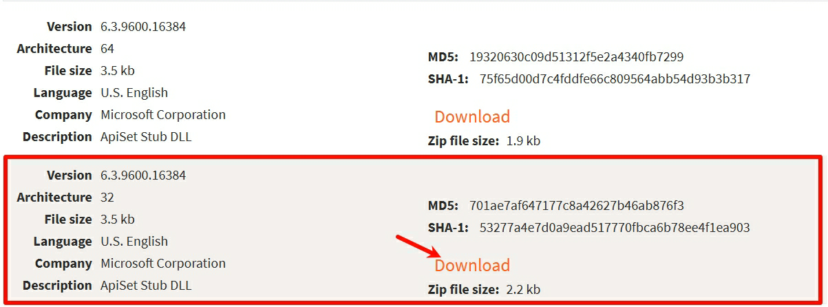
Why am I getting an error about a missing dll file during installation?
Reason: Your system lacks this file type.
Handling Procedure:
- Click api-ms-win-shcore-scaling-l1-1-1.dll free download | DLL-files.com to enter into the download interface.
- Click "Download" button to download the file.
Why can't I drag the model into the software directly?
Reason: When the ELEGOO SatelLite is launched for the first time, the User Interface Consistency (UIC) of the Windows system may prevent the operation to protect the software from any impact. This phenomenon only occurs during the first launch.
Handling Method: Restart the software.
For more information about the ELEGOO SatelLite FAQ, please refer to the detailed page below.
ELEGOO SatelLite FAQ
¶ Help us improve
If you have any ideas about the wiki pages, please let us know via ELEGOO official feedback channel