¶ Tools and Materials
- 2.5mm Allen key x 1
- A new limit switch

¶ Tutorial Video
¶ Instruction
- Power off the printer and unplug the power cord.
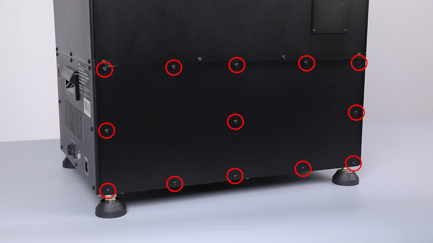
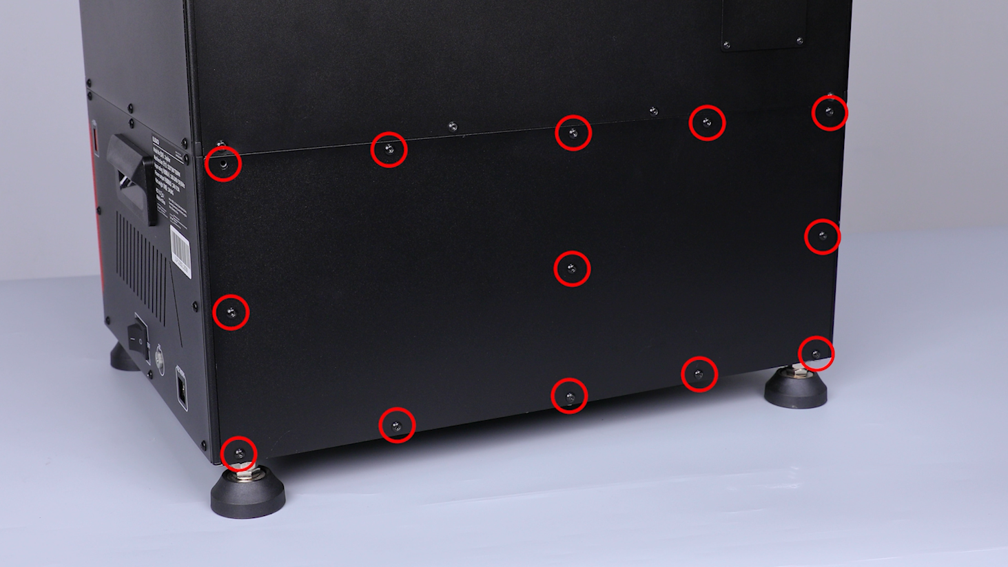
- Loosen the 13 screws securing the back cover using a 2.5 mm Allen key.
- Lay the back cover flat and remove the back cover. Cut off the cable ties securing the cables using a pair of diagonal pliers.
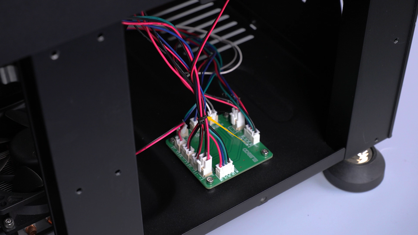
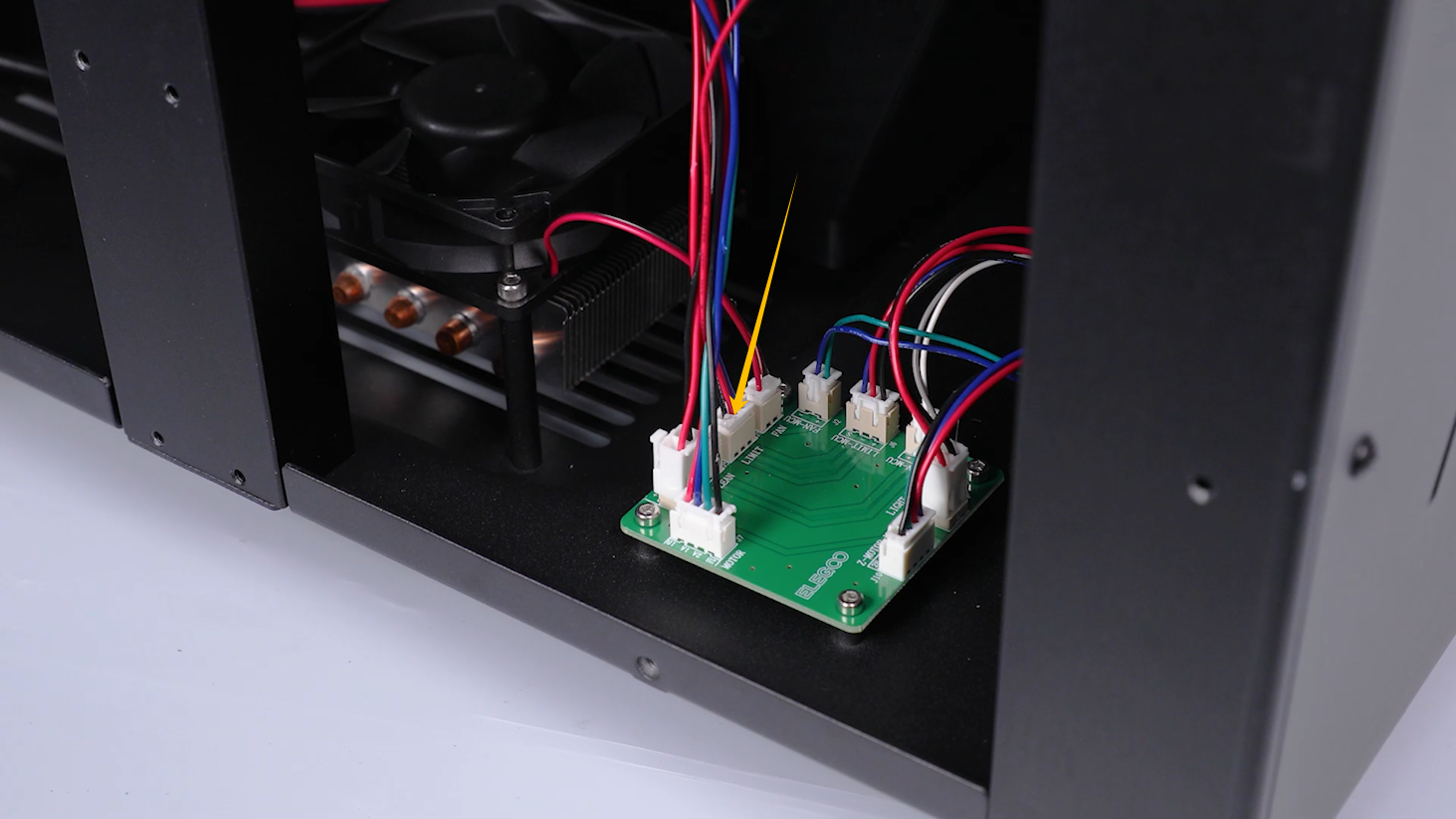
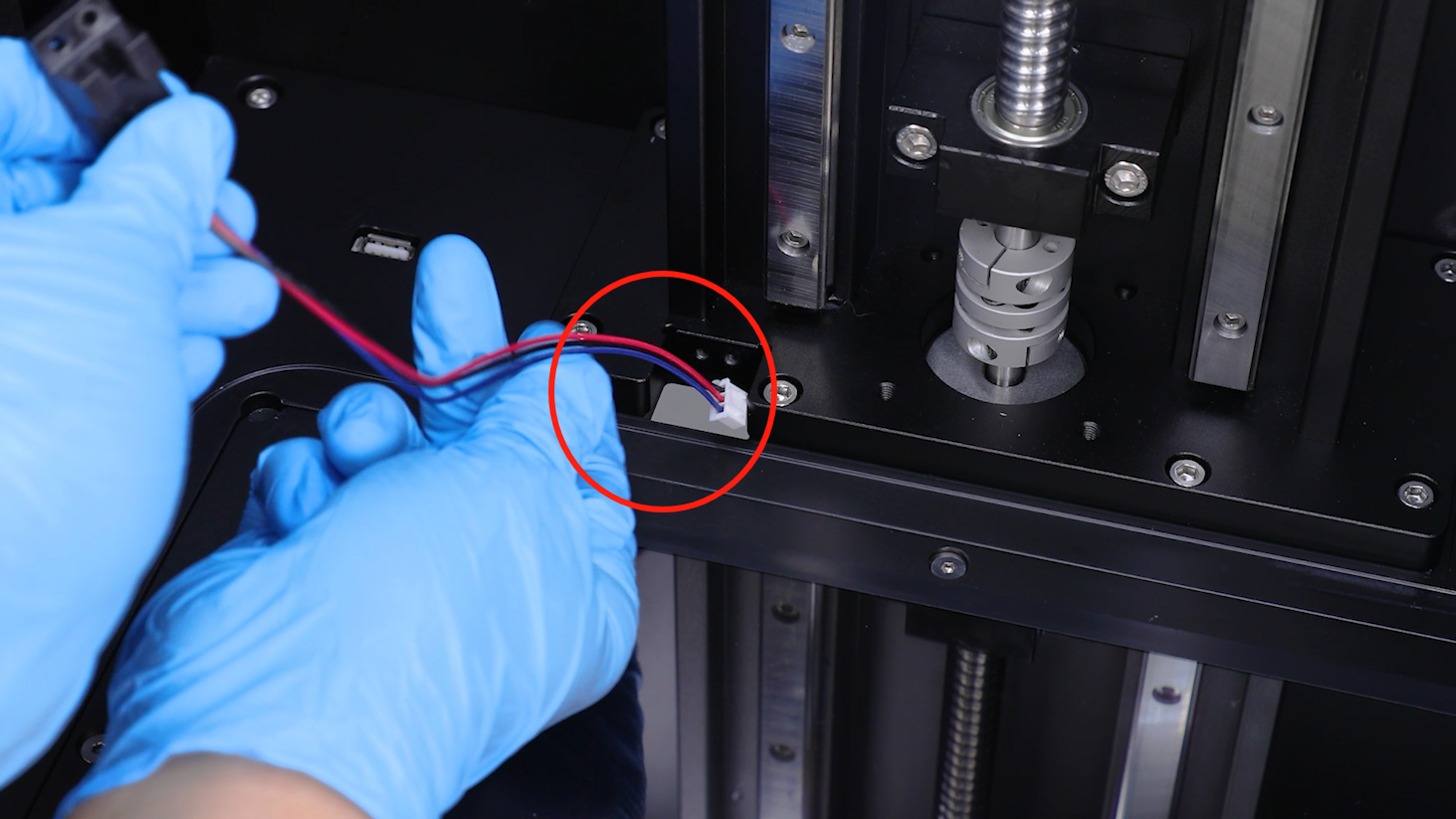
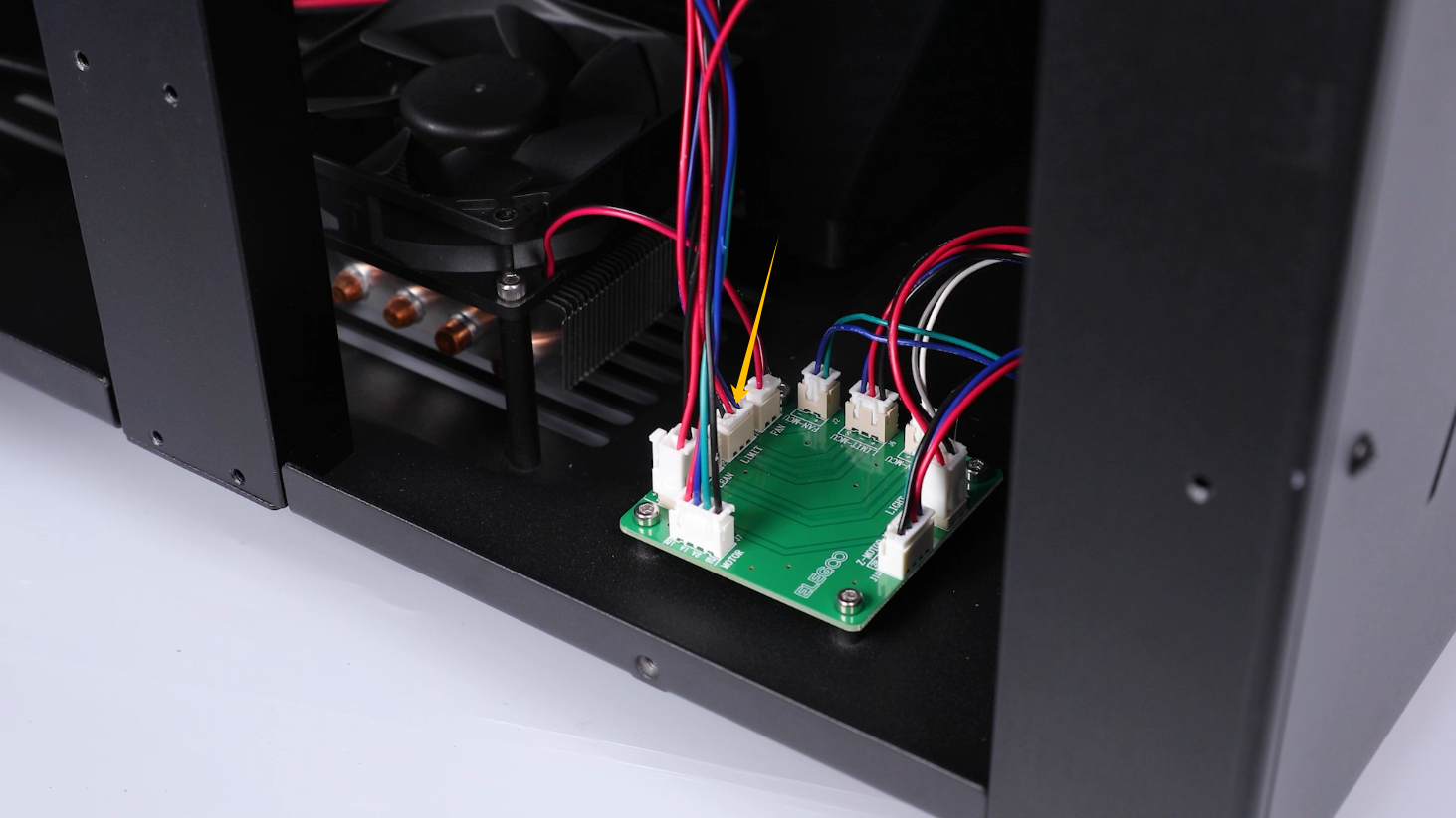
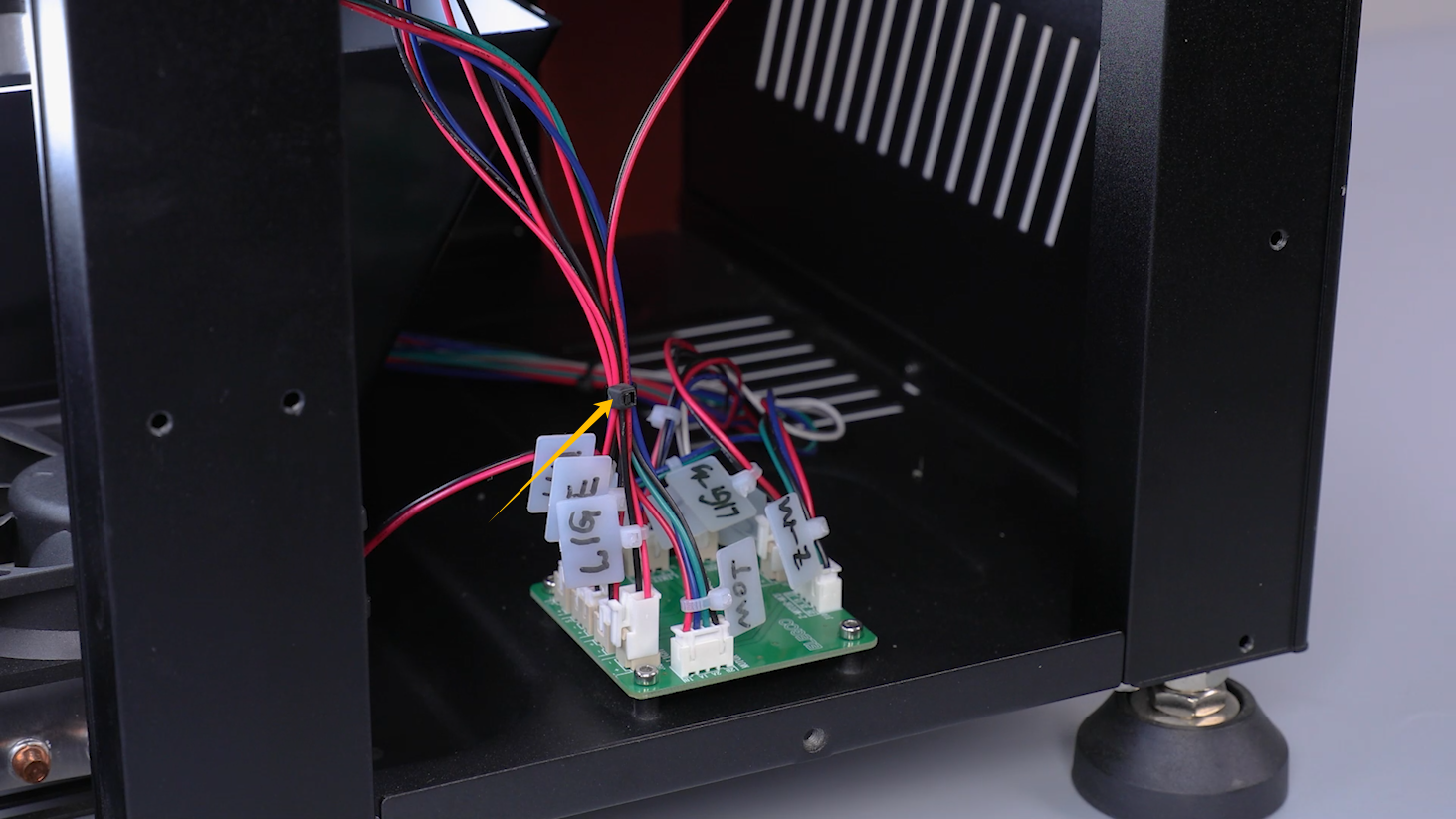
- Disconnect the cables of the limit switch on the adapter board.
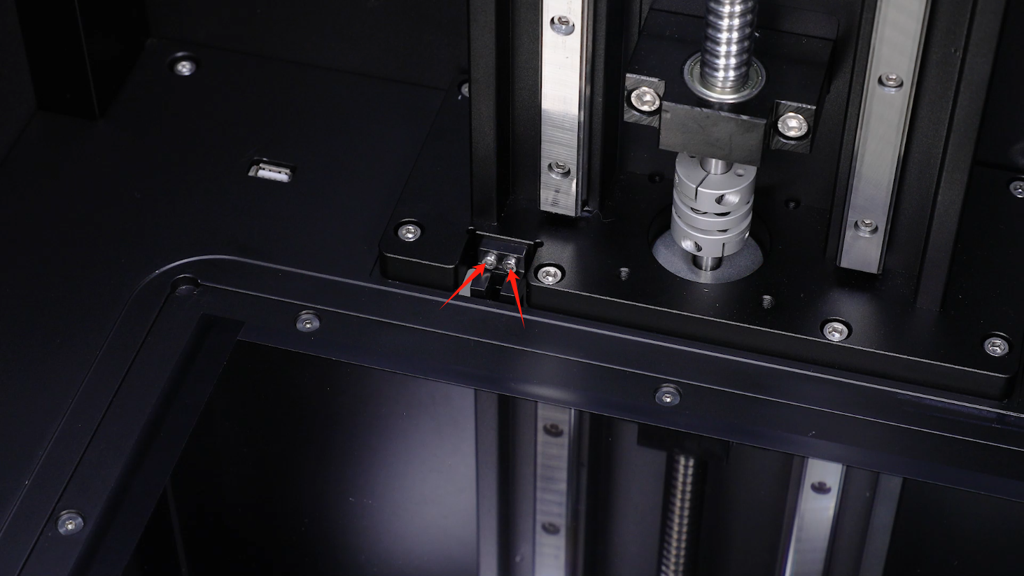
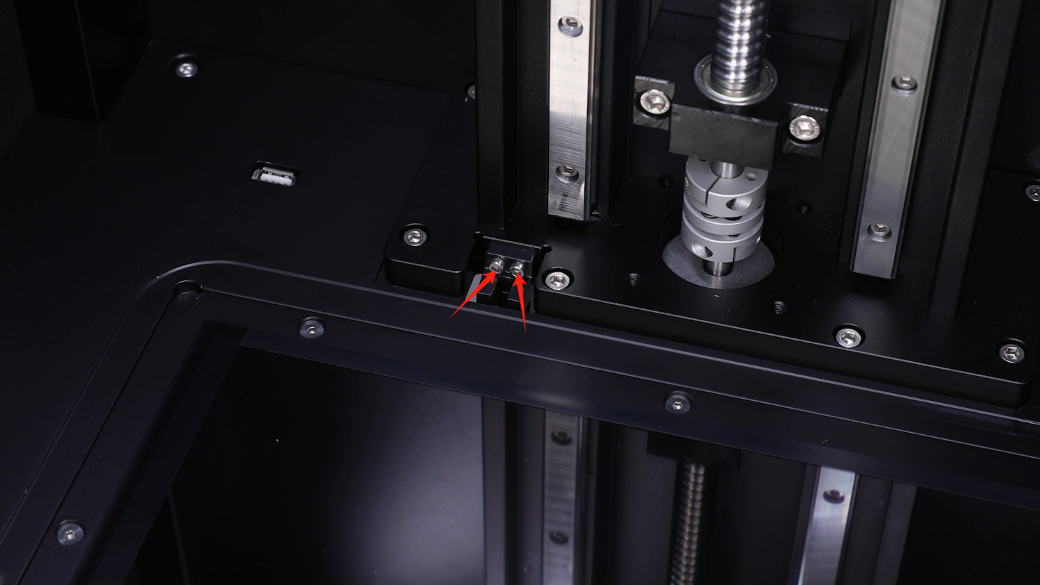
- Loosen the two screws securing the limit switch using a 2.5 mm Allen key. When loosening the last screw, hold the limit switch using a pair of tweezers to to prevent it from falling.
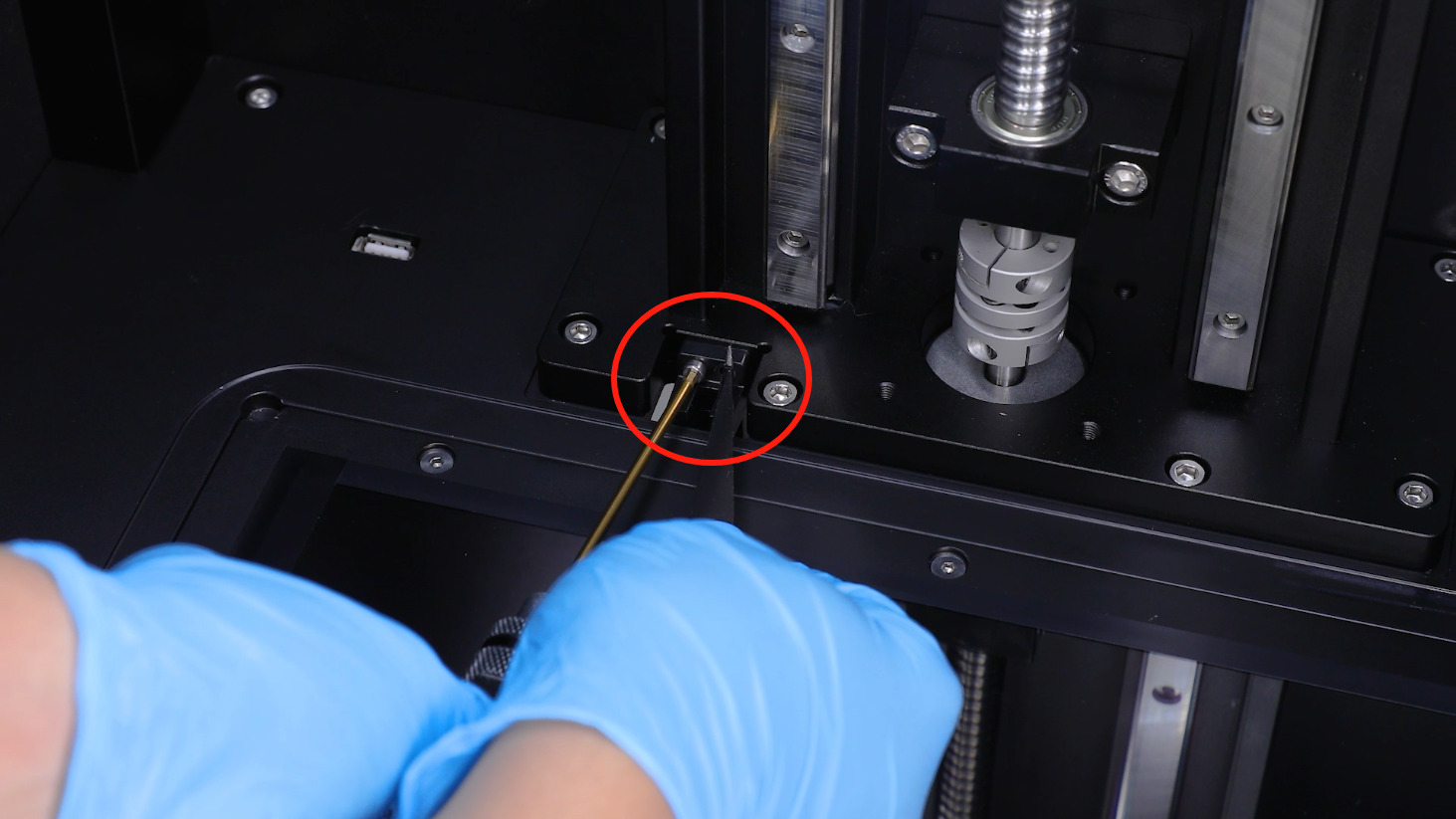
- Organize the cables. Remove the old limit switch assembly.
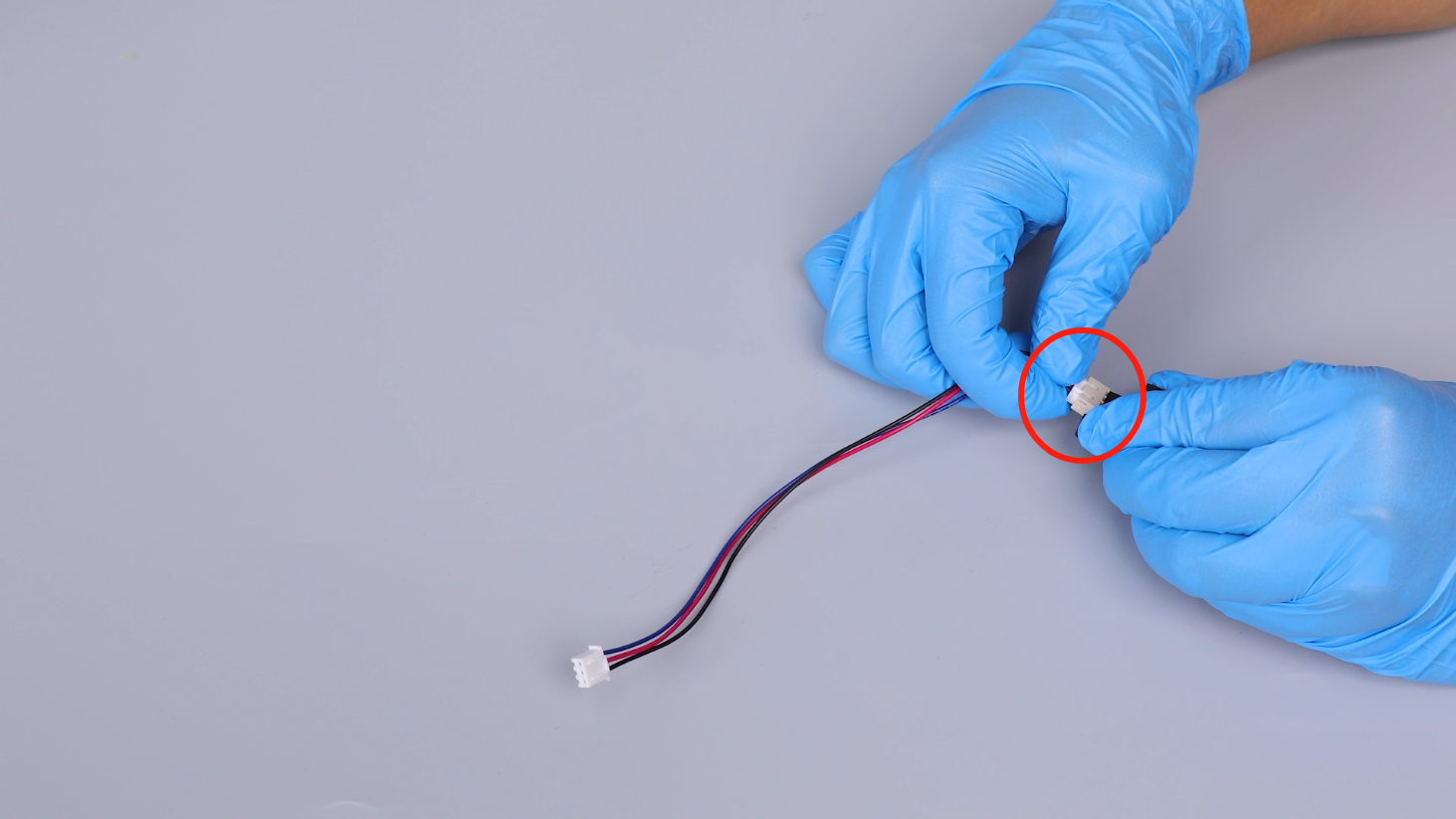
- Unplug the cables of the limit switch port. Remobe the old limit switch.
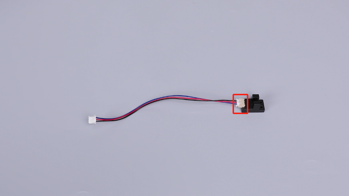
- Prepare the new limit switch. Insert the cables of the limit switch port.
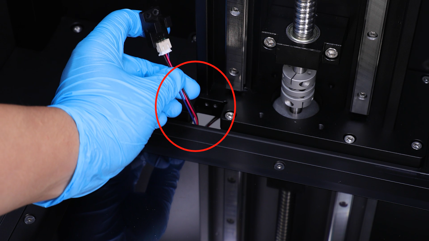
- Pass the limit switch cable through the wire hole and place it inside the printer.
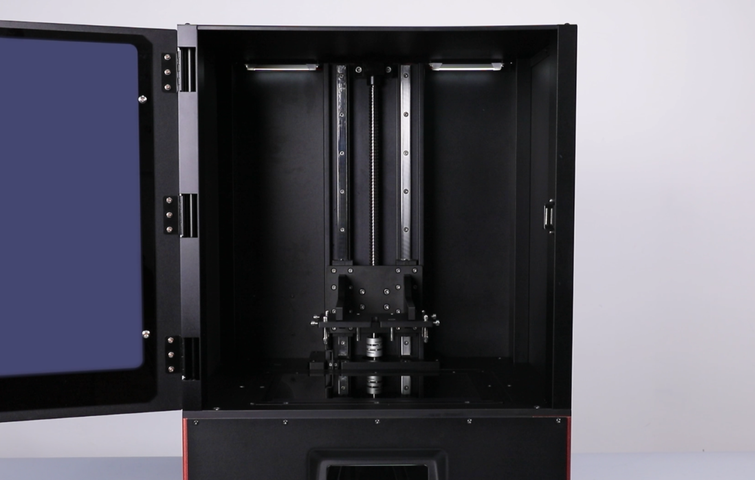
- Align the limit switch with the screw holes and put the limit switch in the installation position. Tighten the two screws securing the limit switch using a 2.5 mm Allen key.
- Insert the limit switch cables into the adapter board port.
- Secure the cables using cable ties.
- Align the back cover with the screw holes and put it in the installation position. Tighten 13 screws using a 2.5 mm Allen key.
- Power on the printer. Select Tools - Calibration - Next. The printer is ready for use if teh Z axis retures to homing position.