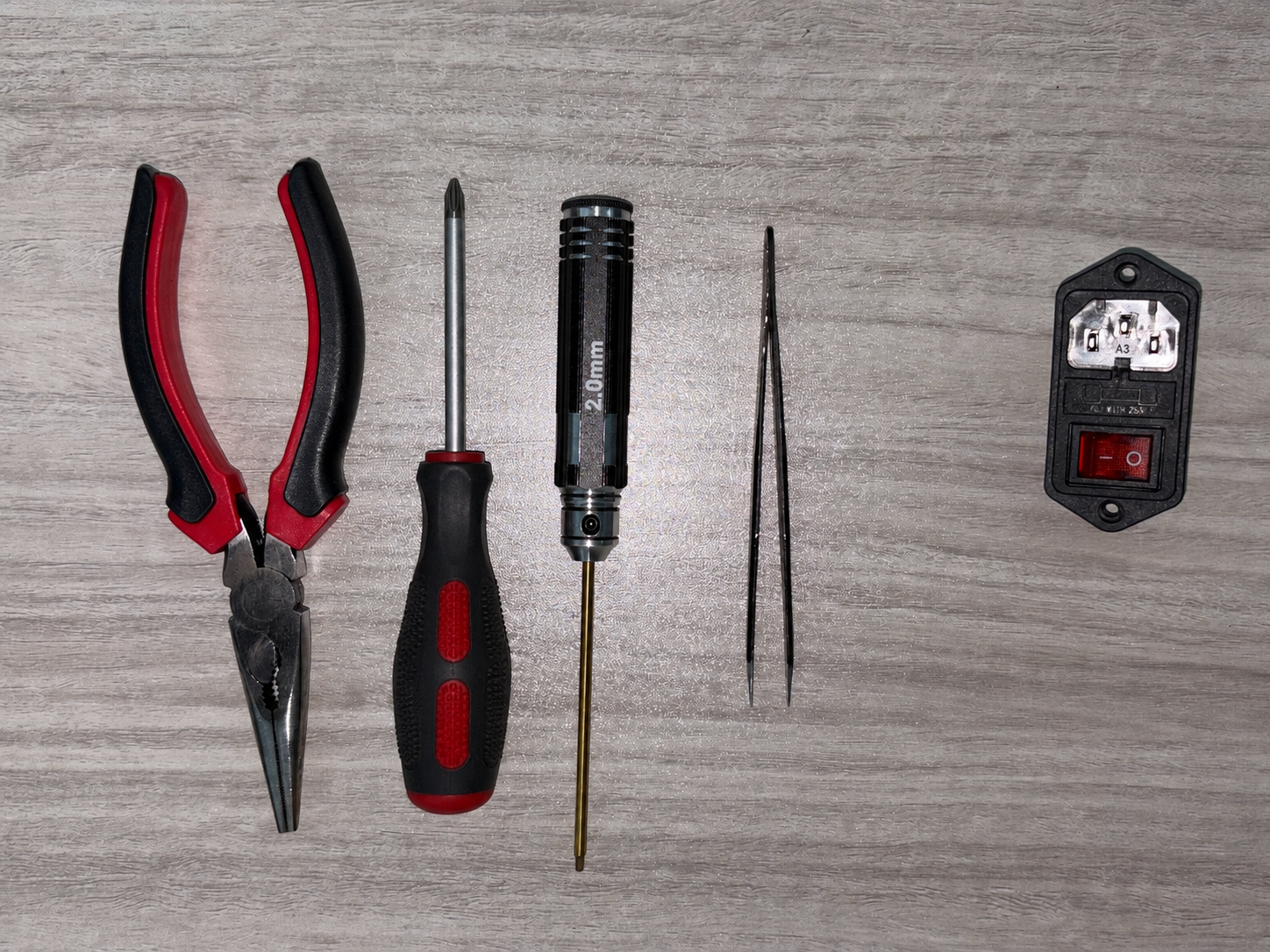
¶ Required Tools and Materials
- Phone/Camera (to take photos of the original wiring connections)
- Phillips screwdriver
- 2.0 mm Allen screwdriver
- Needle-nose pliers
- Tweezers
- New power switch
Safety Precautions
This procedure involves wiring for AC mains power. Before starting, turn off the printer's power switch and unplug the power cord. Do not connect the printer to AC mains power while removing, installing, or inspecting any wire terminals.
¶ Preparation
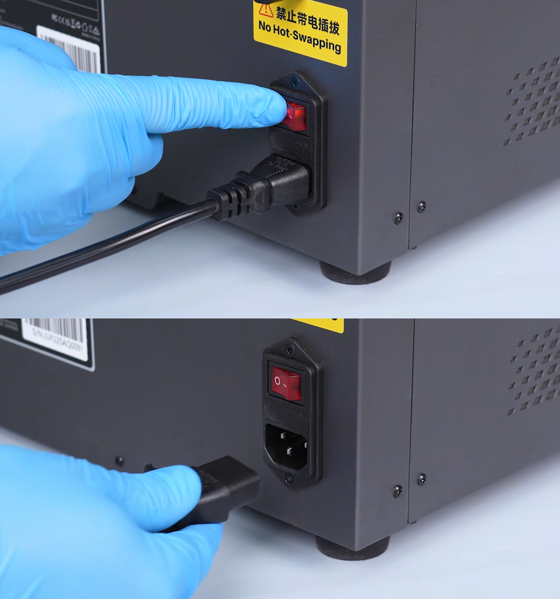
Turn off the power switch and unplug the power cord.
¶ Disassembly
¶ Remove the Left Panel
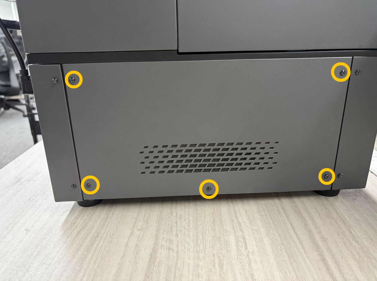
- Use a 2.0 mm Allen screwdriver to remove the five screws securing the left panel.
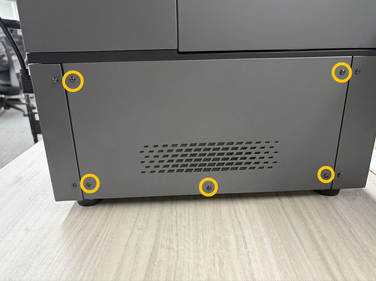
- Remove the left panel.
¶ Disconnect the Power Supply Wire Terminals
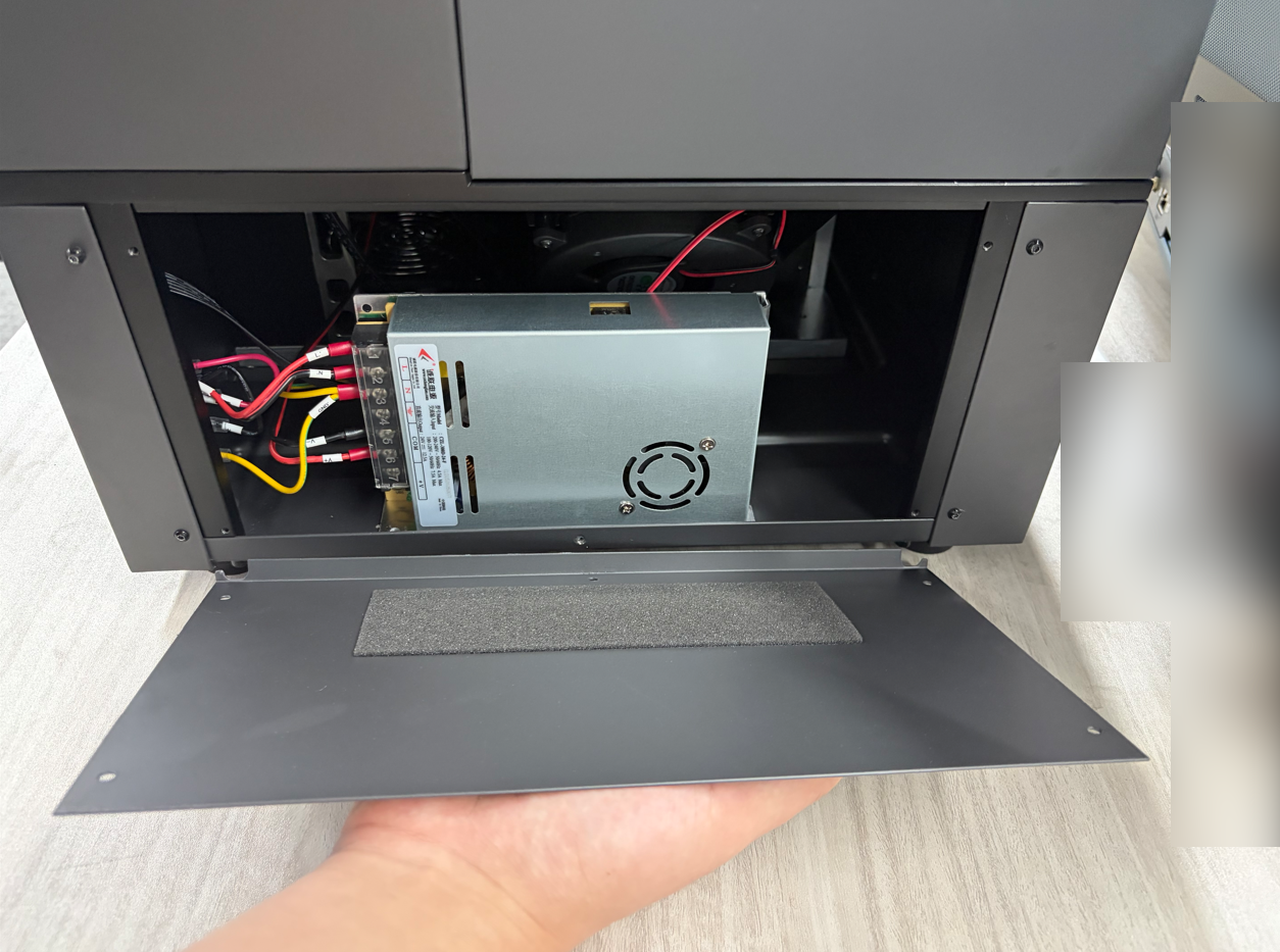
- Open the power supply cover.
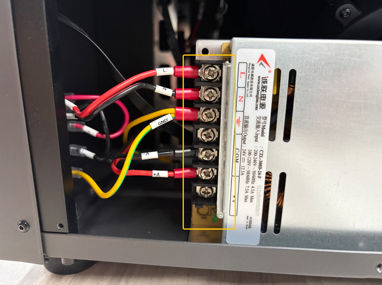
- Use a Phillips screwdriver to loosen the screws securing the L, N, and GND wire terminals.
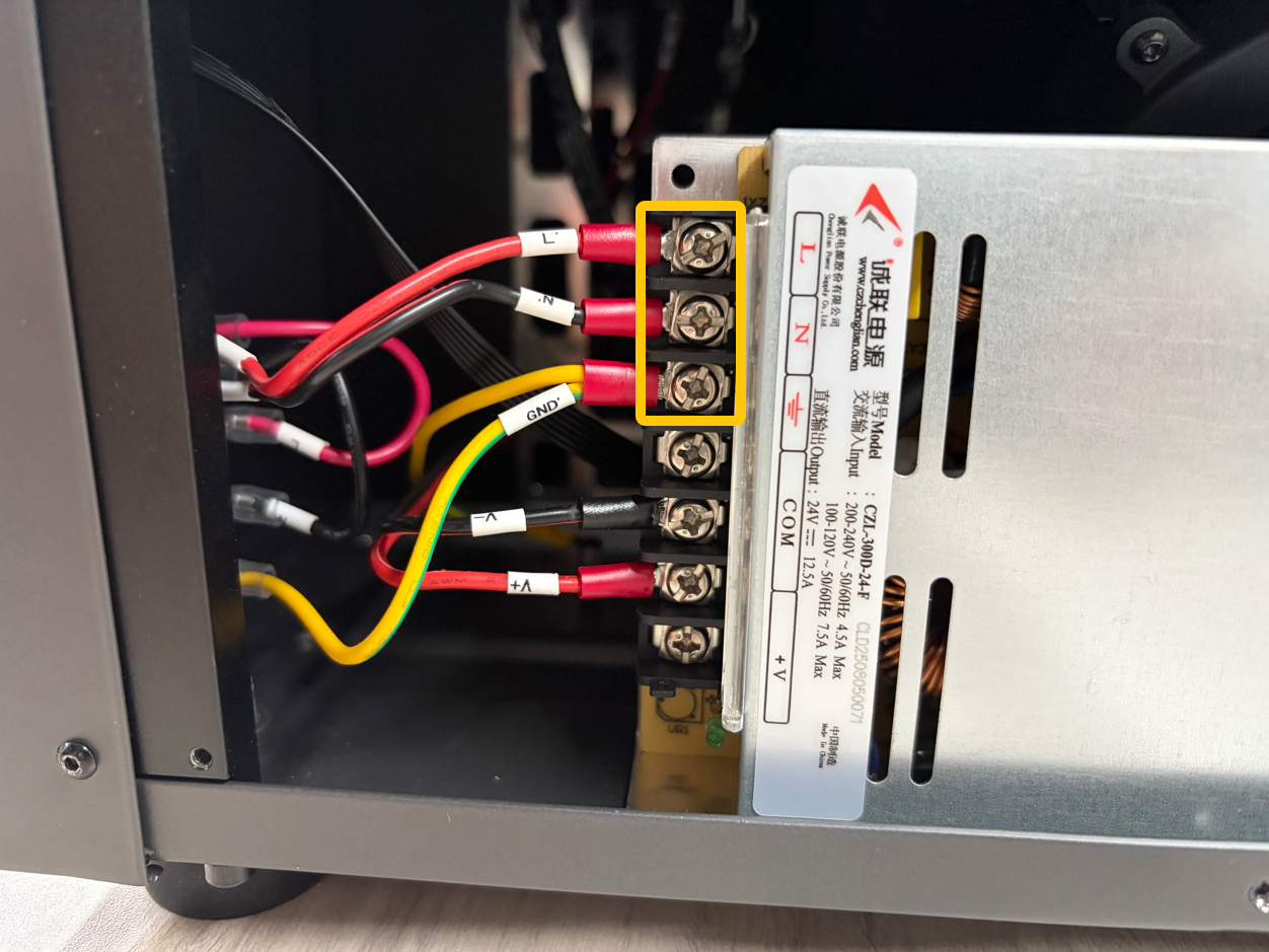
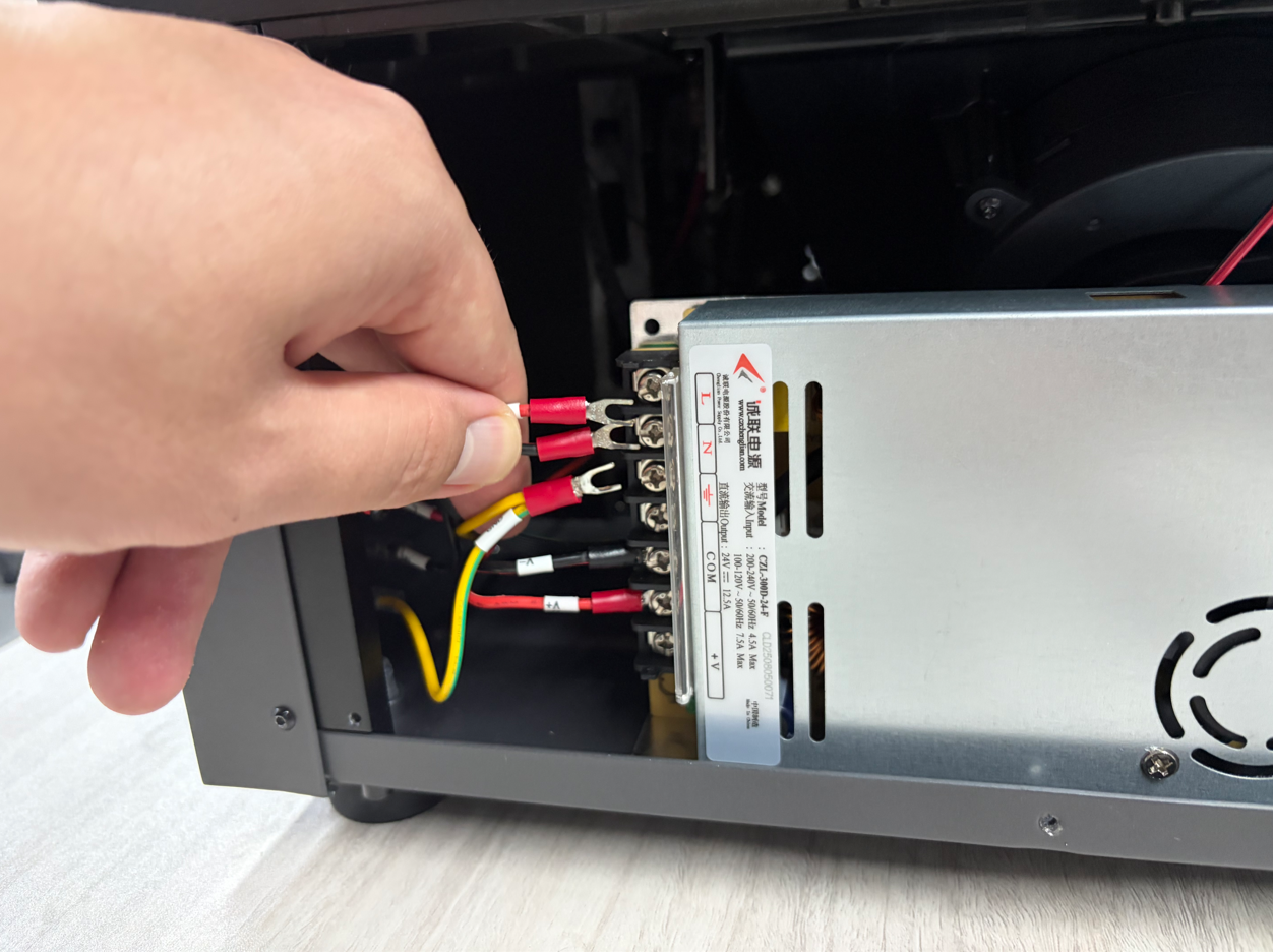
- Disconnect the wire terminals.
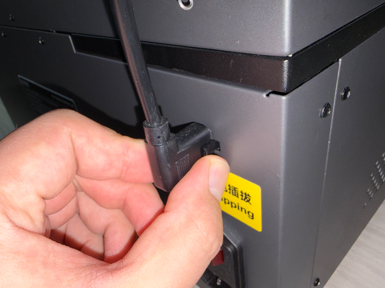
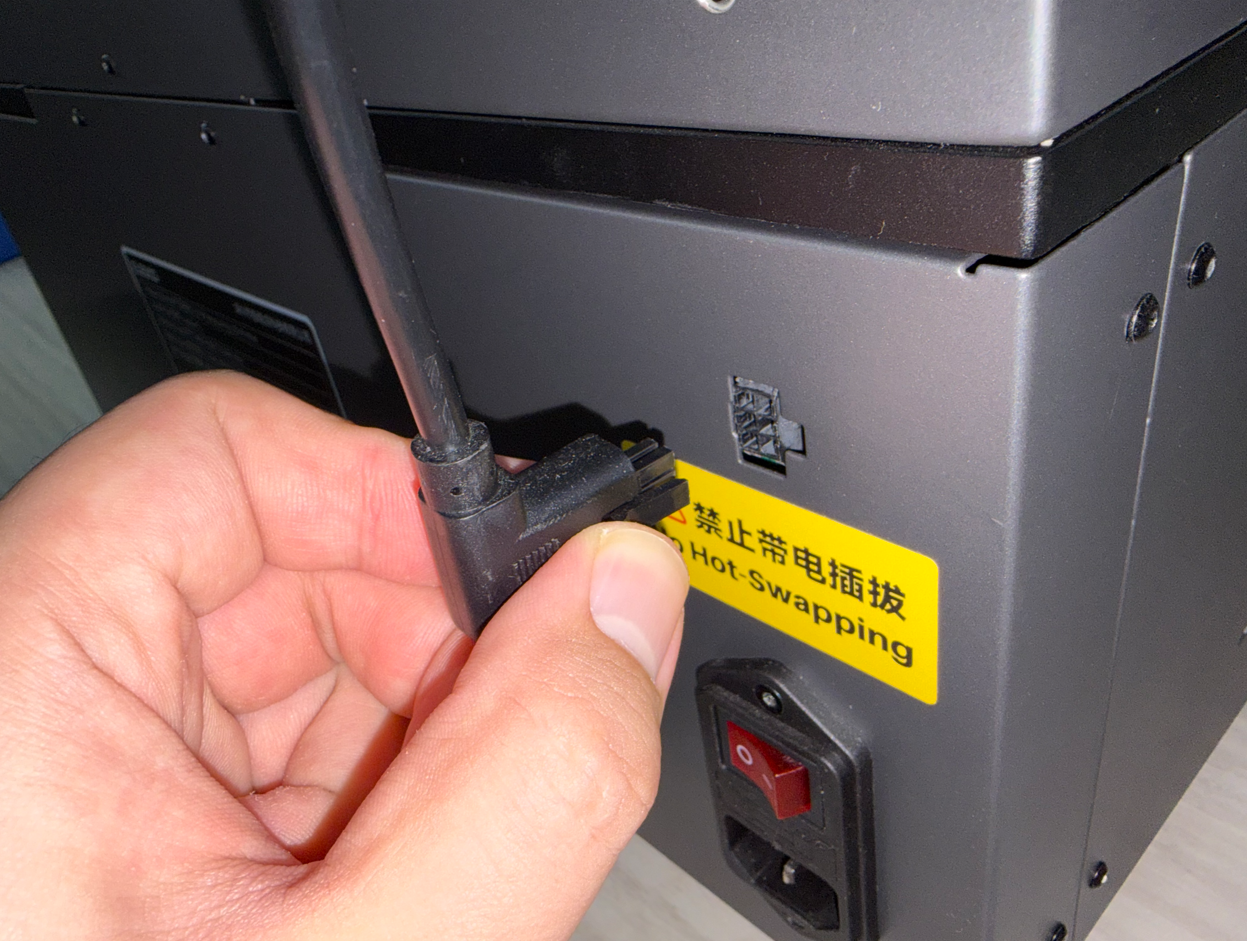
¶ Disconnect the Automatic Resin Feeding Connector
¶ Remove the Rear Panel
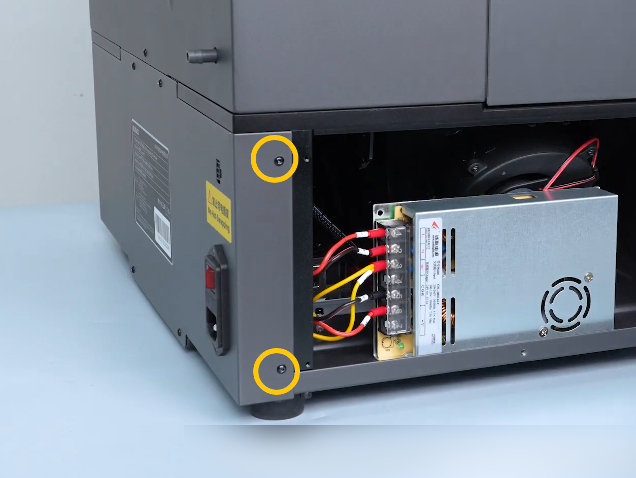
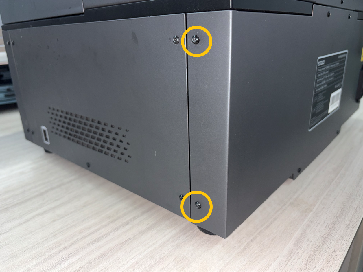
- Use a 2.0 mm Allen screwdriver to remove the four screws securing the rear panel.

- Use a 2.0 mm Allen screwdriver to remove the four screws, securing both sides of the rear panel.
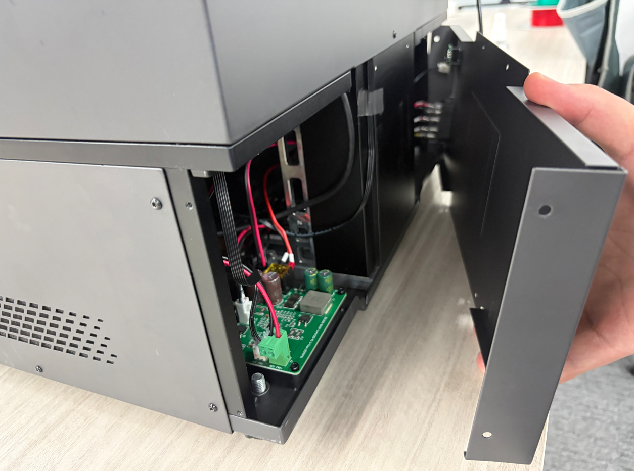
- Slowly open the rear panel.
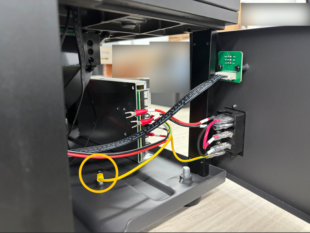
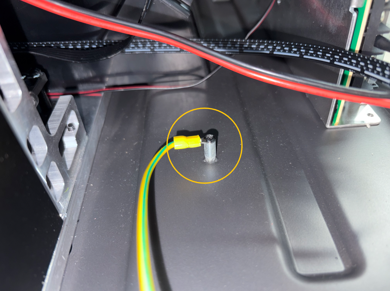
¶ Disconnect the Ground Wire
Use a 2.0 mm Allen screwdriver to remove the screw, securing the ground wire terminal.
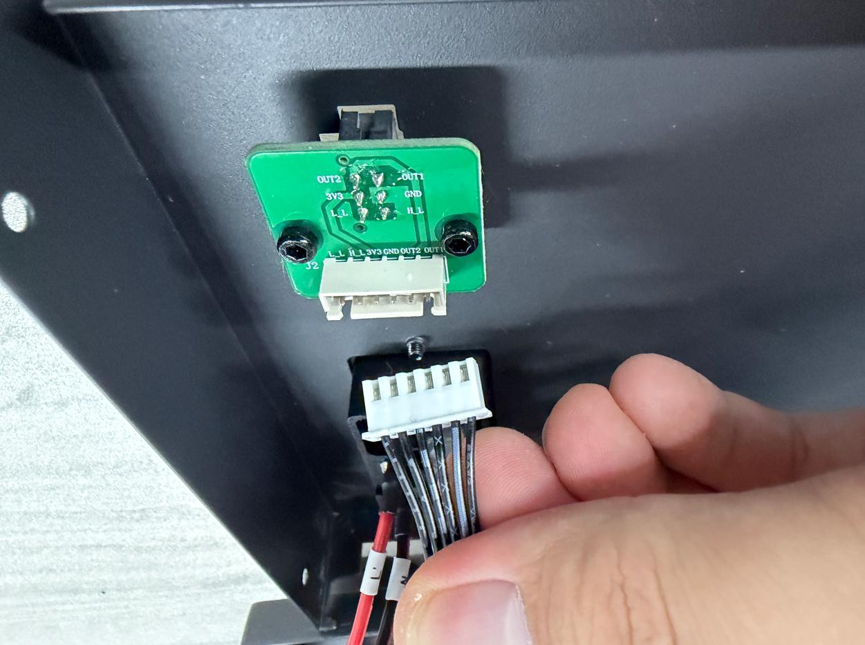
¶ Disconnect the Feeder Cable Connector
- Disconnect the feeder cable connector.
- Set the rear panel aside on the table.
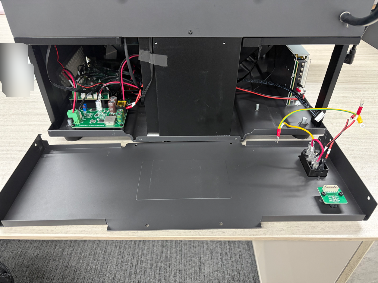
¶ Disconnect the Wire Terminals
Note: Take a photo of the original power switch wiring and save it as a reference for installation. This helps prevent incorrect wiring during reassembly.
- Move the insulation sleeves away from the terminals.
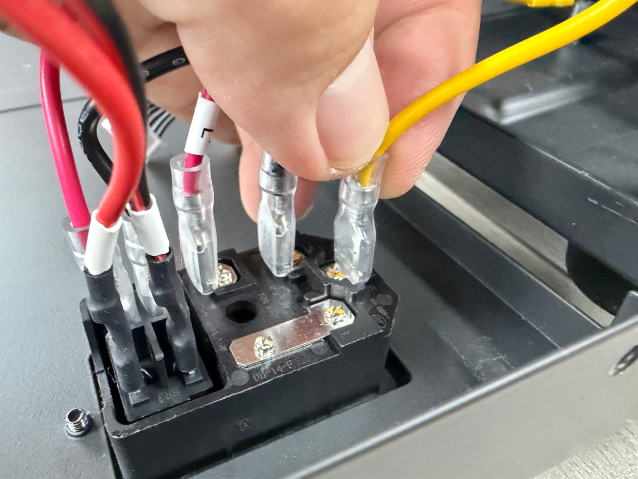
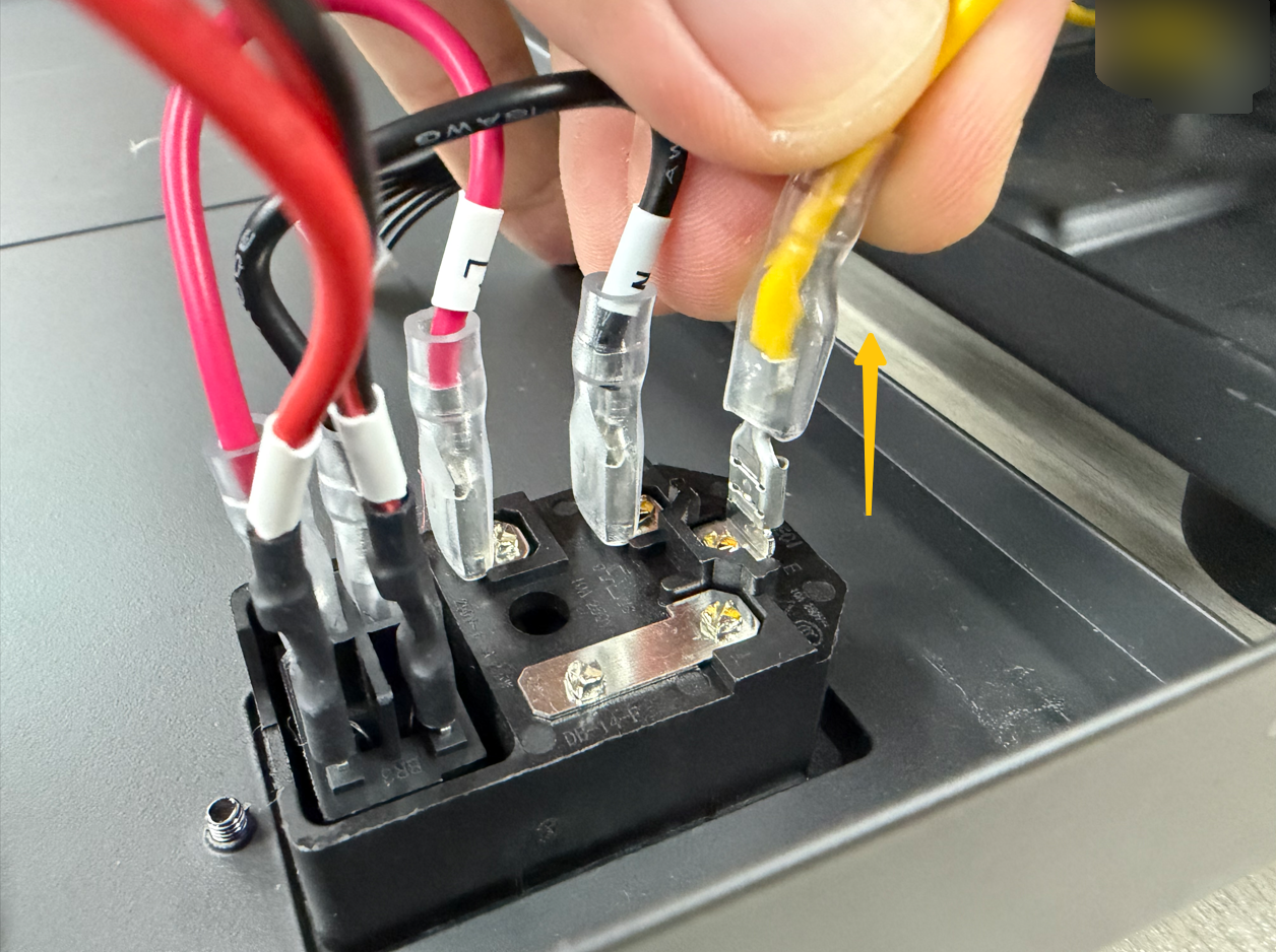
- Use needle-nose pliers to disconnect the wire terminals.
Note: If a wire terminal is difficult to remove, use tweezers to loosen it or gently rock it from side to side. Once the terminal is loosened, remove it. Do not forcefully pull on the wire terminal.
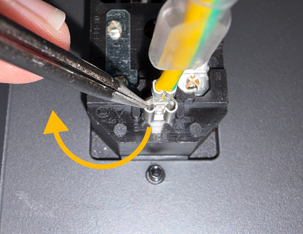
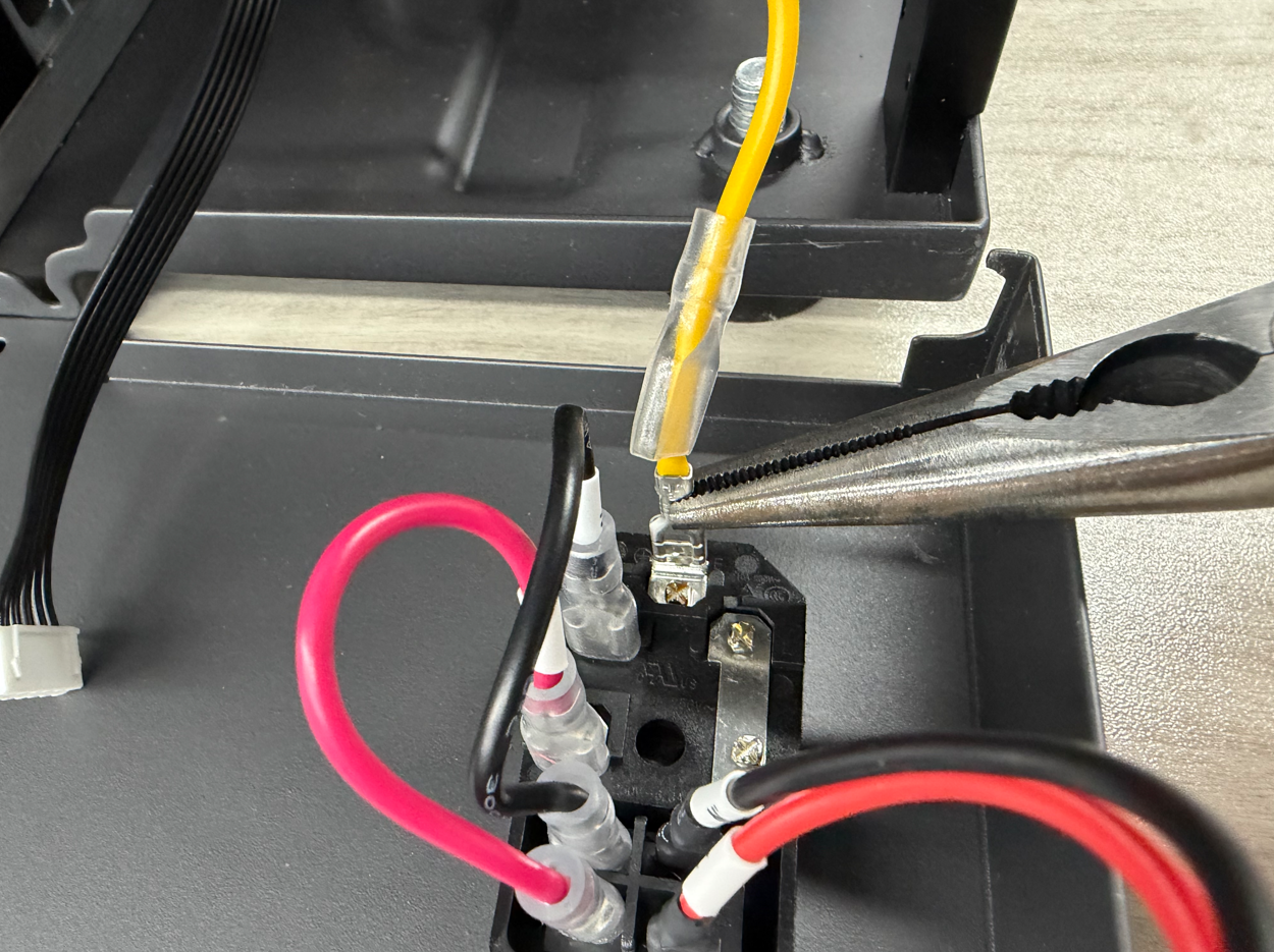
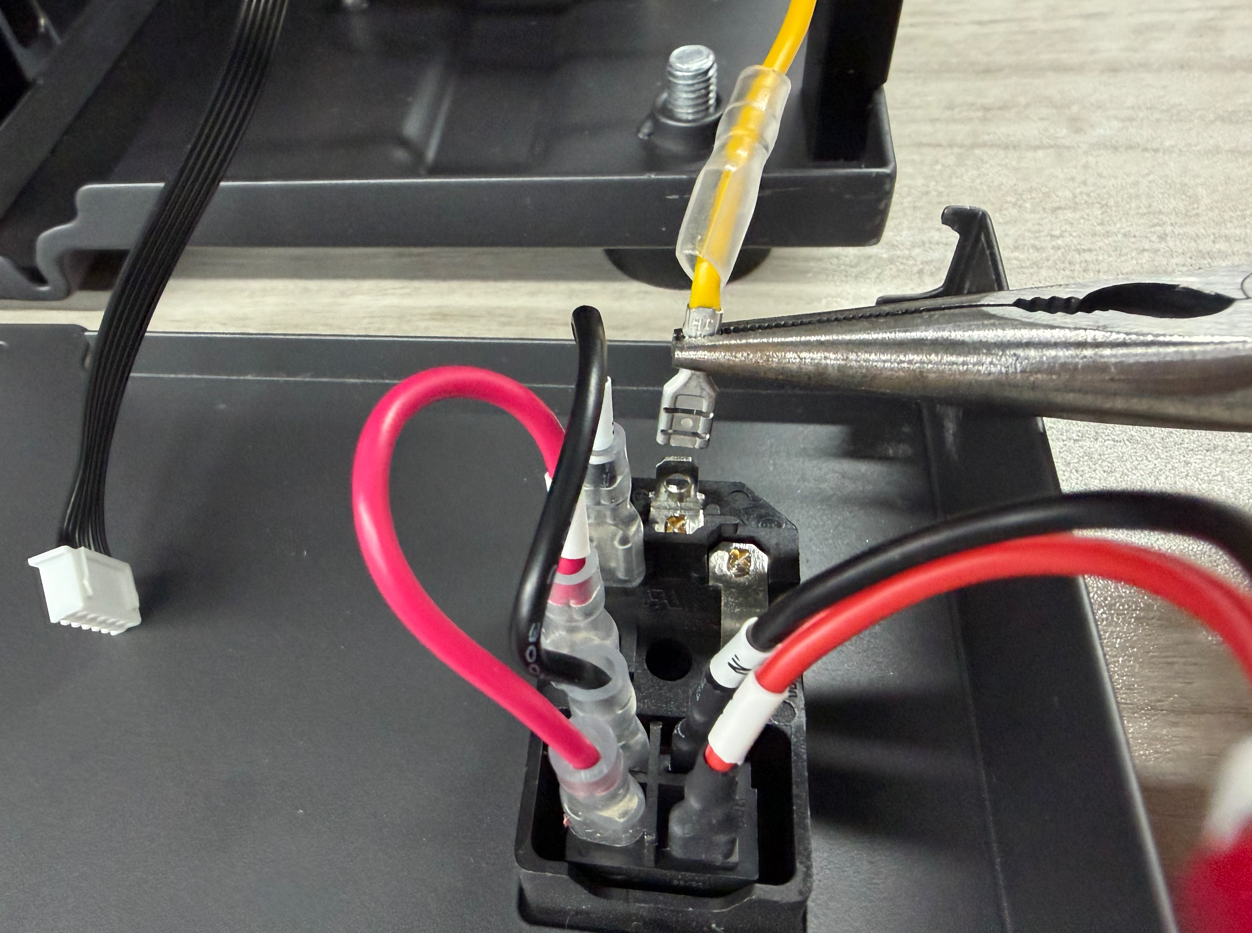
- Repeat the same procedure to disconnect the other wire terminals.

¶ Remove the Old Power Switch
- Turn the rear panel over.
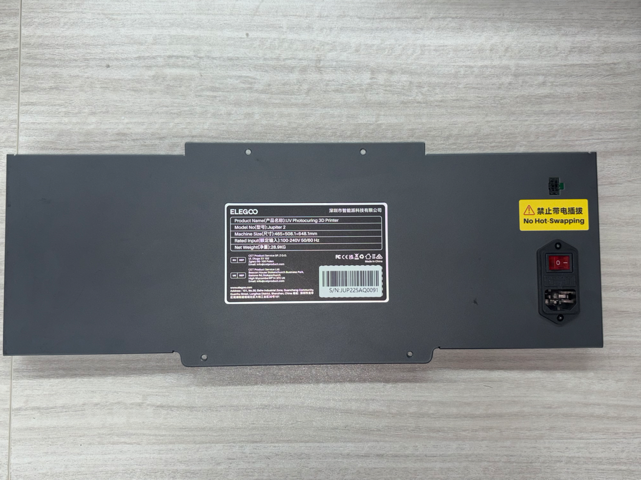
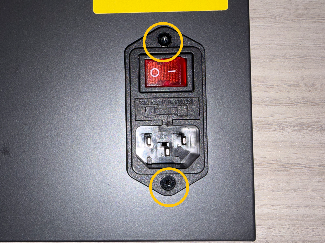
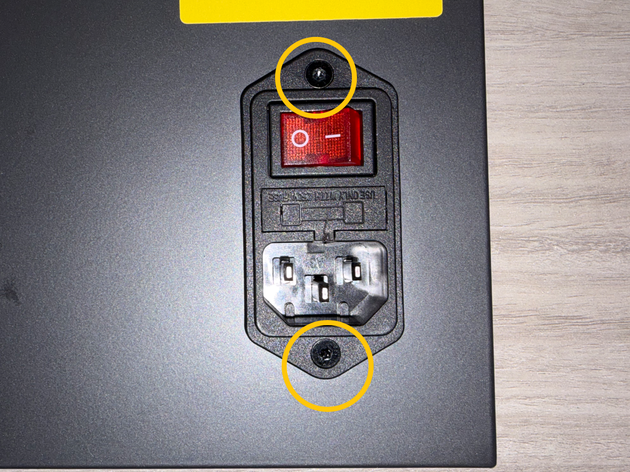
- Use a 2.0 mm Allen screwdriver to remove the two screws securing the power switch.
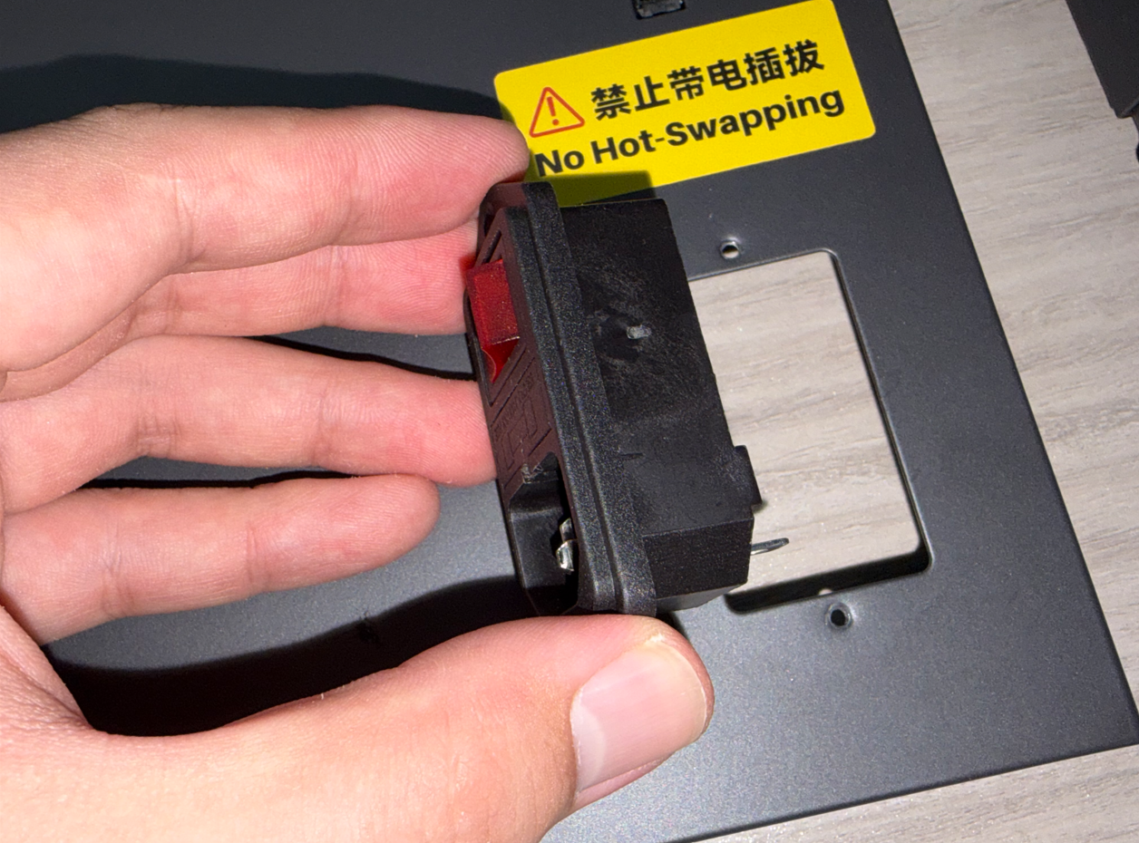
- Remove the power switch.
¶ Installation
¶ Install the New Power Switch
- Take the new power switch and place it into the slot on the rear panel.

- Use a 2.0 mm Allen screwdriver to tighten the two screws securing the power switch.
¶ Connect the Wire Terminals
- Turn the rear panel over.
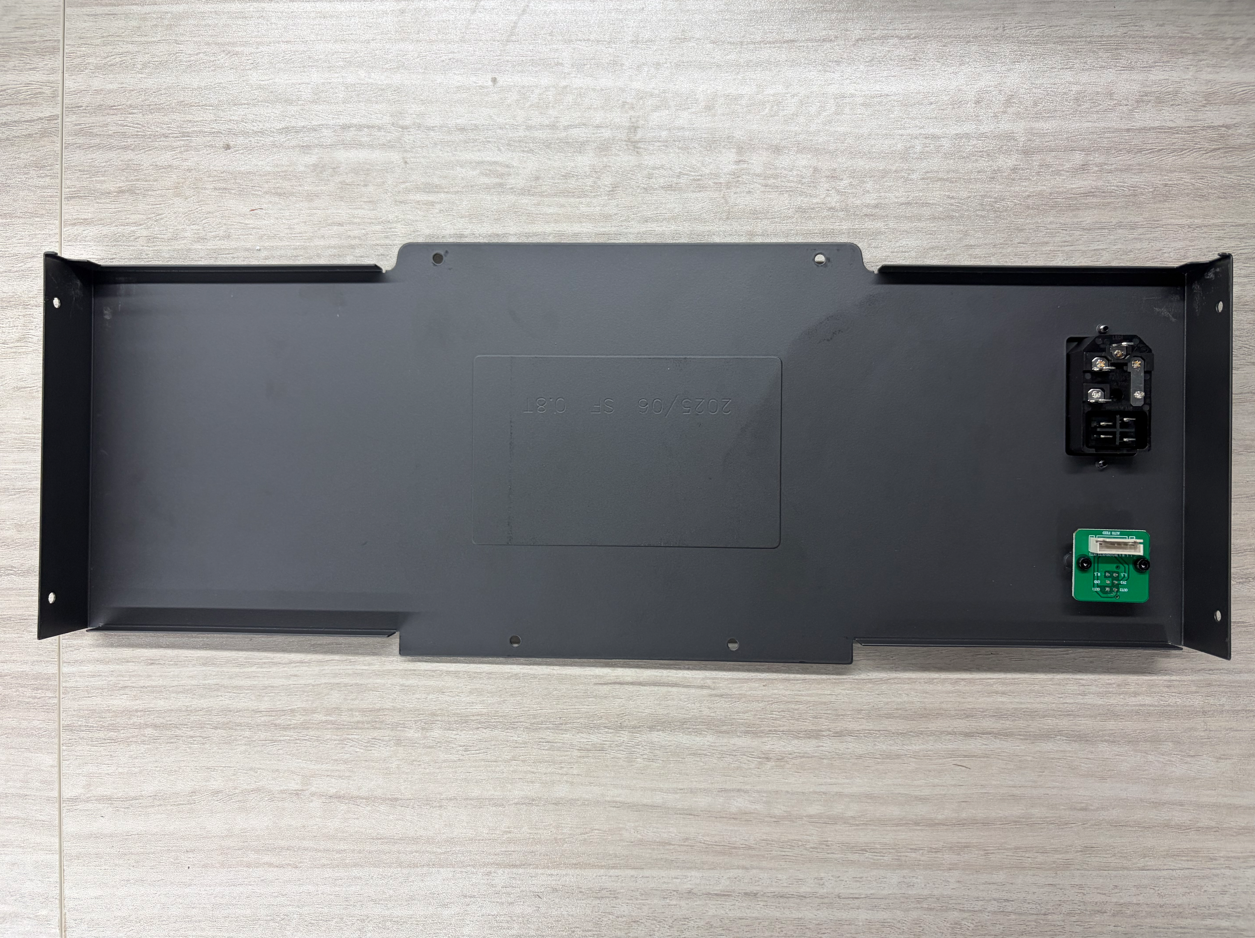
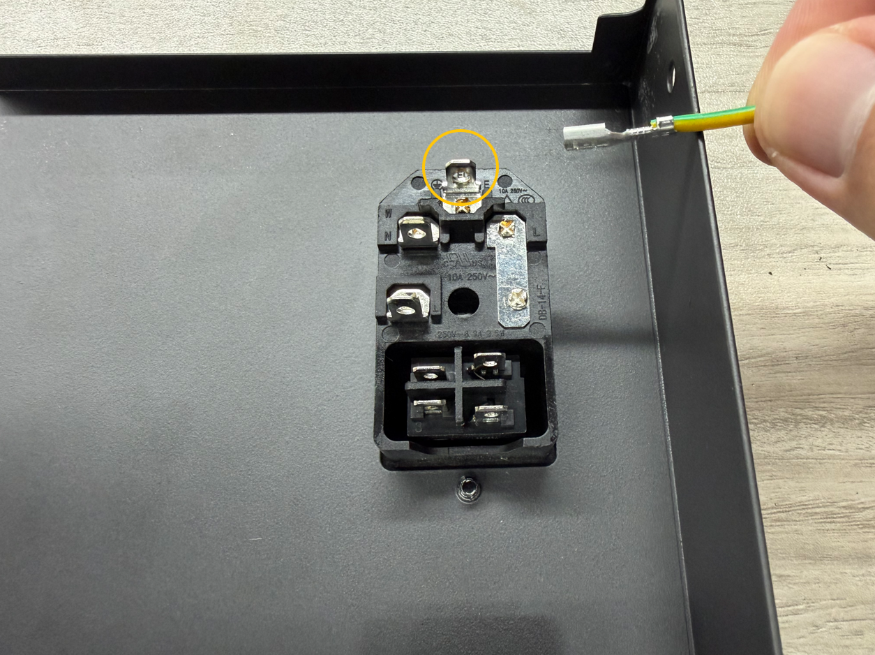
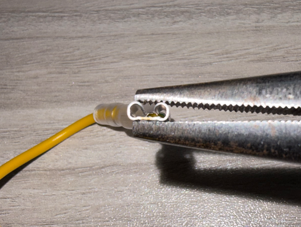
- Insert the PE terminal of the power switch wire into the port shown below.
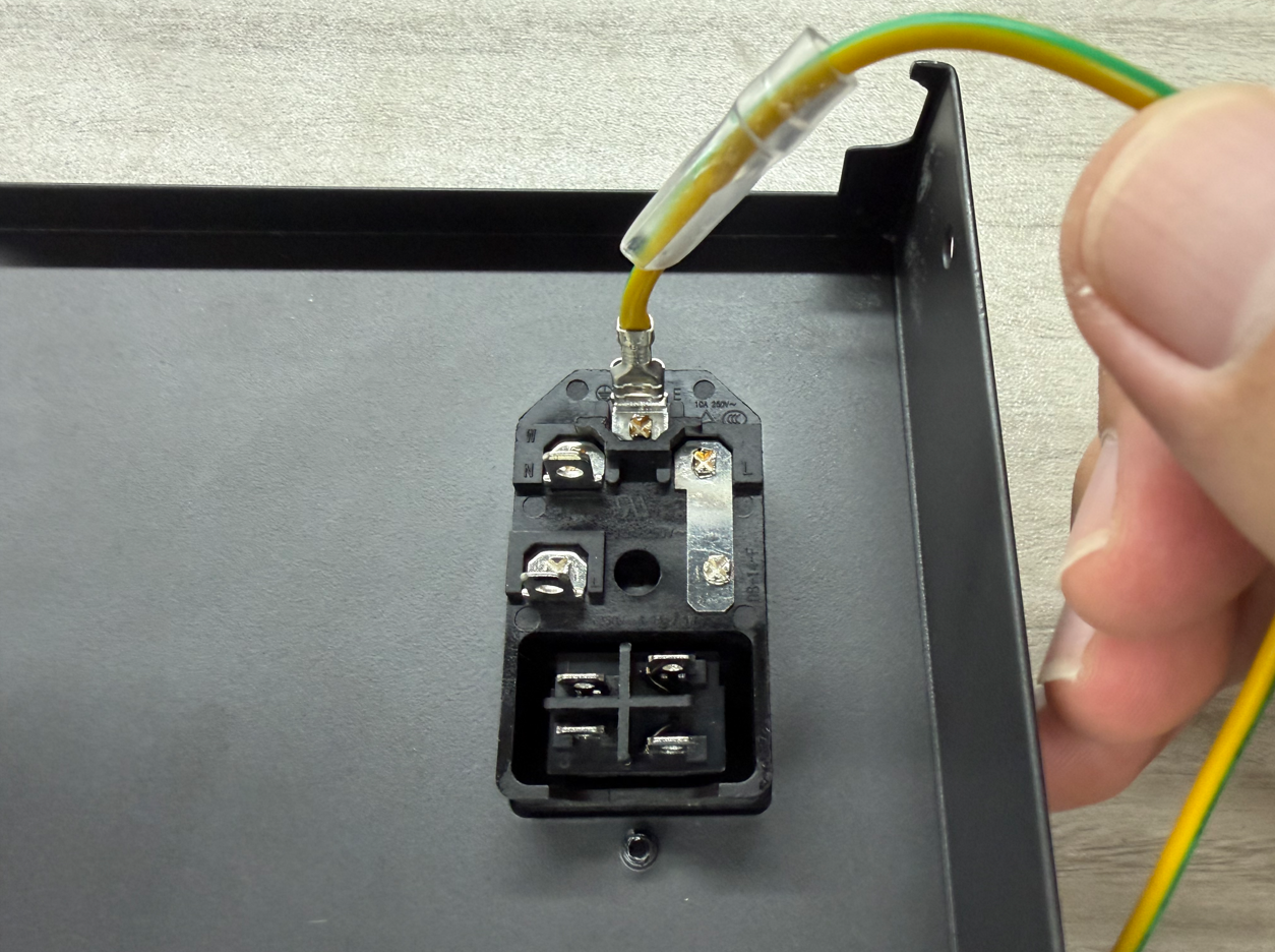
Note: If the terminal is loose after connection, use needle-nose pliers to tighten the terminal and then reconnect it.
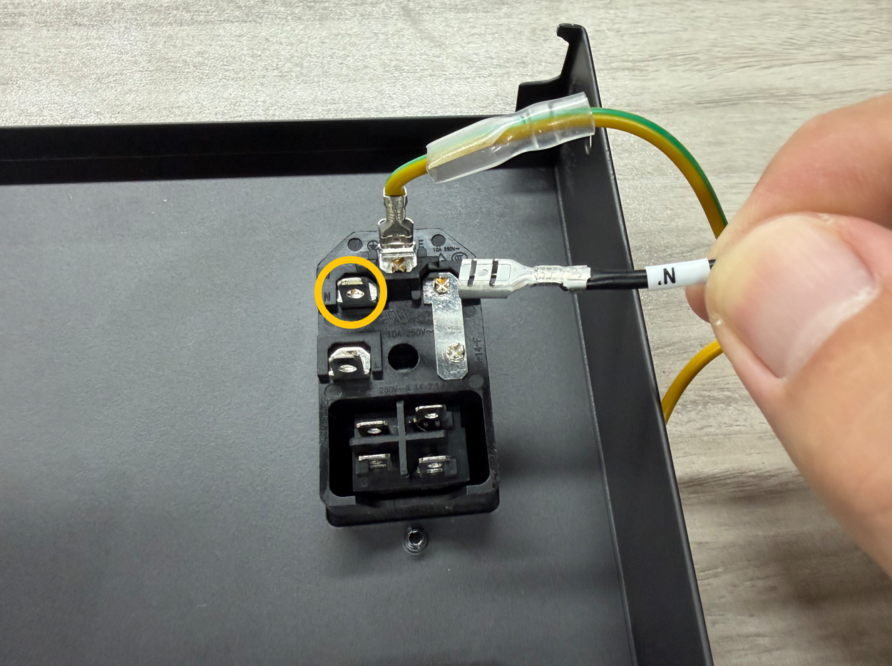
- Insert the N terminal of the power switch wire into the port shown below.
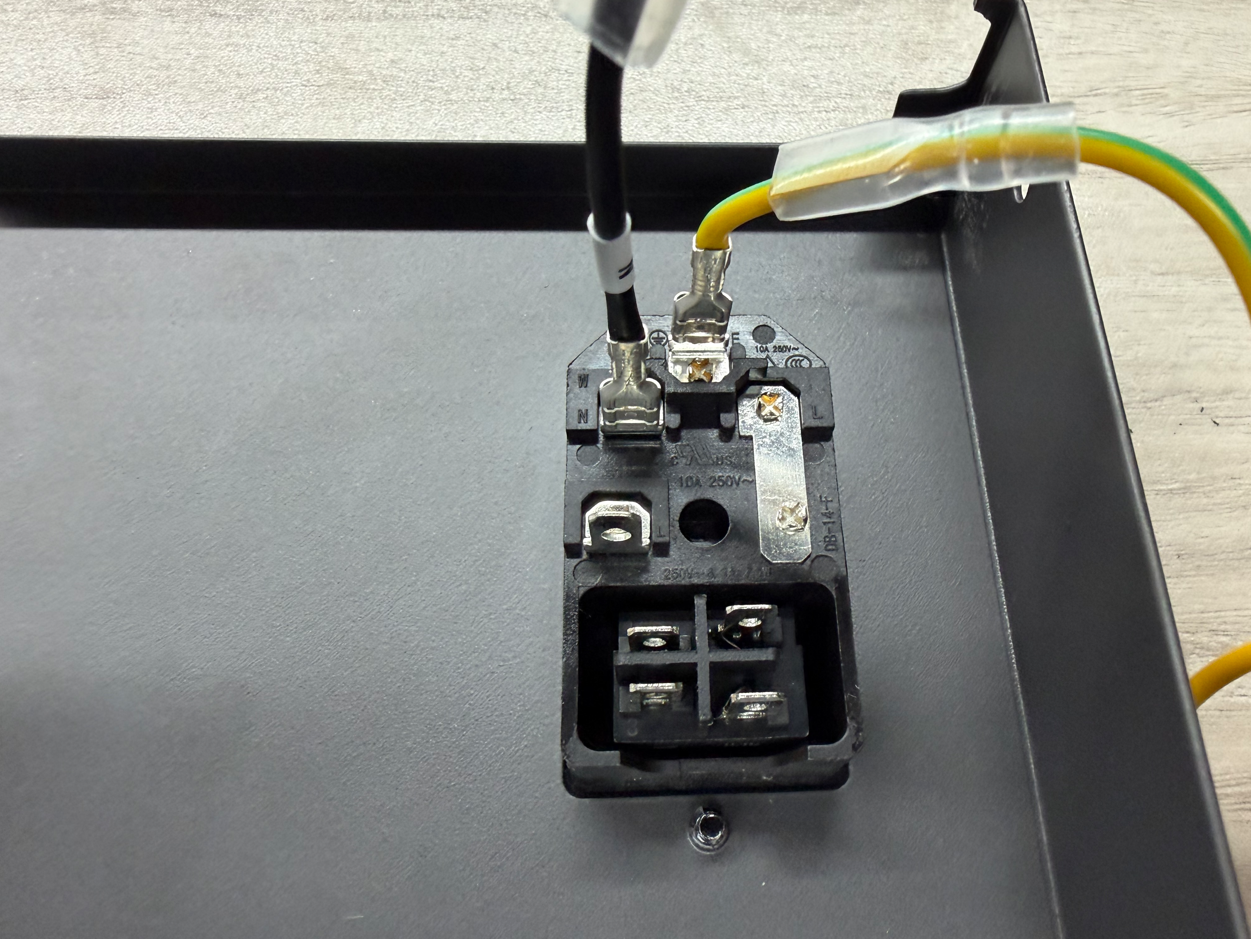
- Connect the other end of the N wire from the power switch to the port shown below.

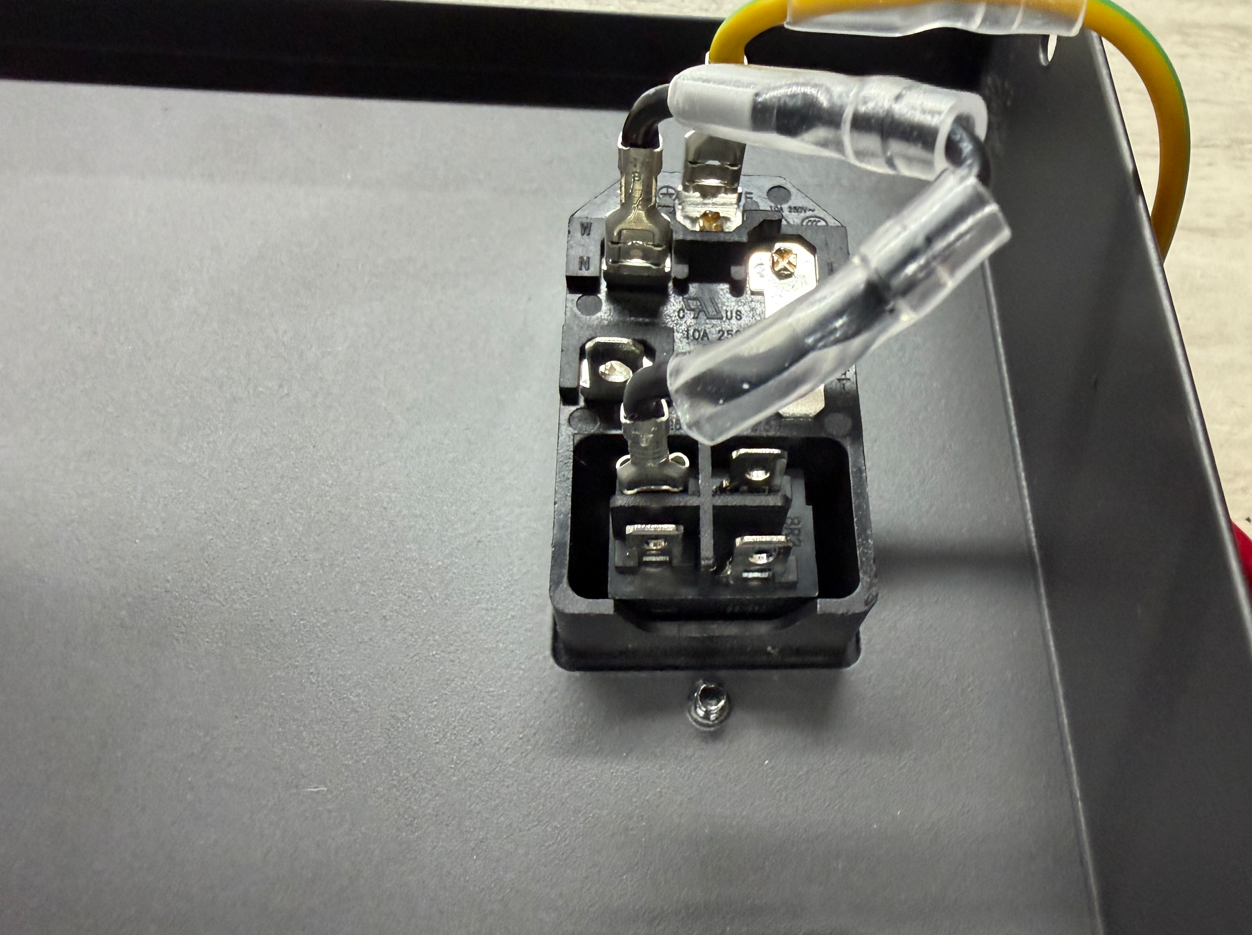
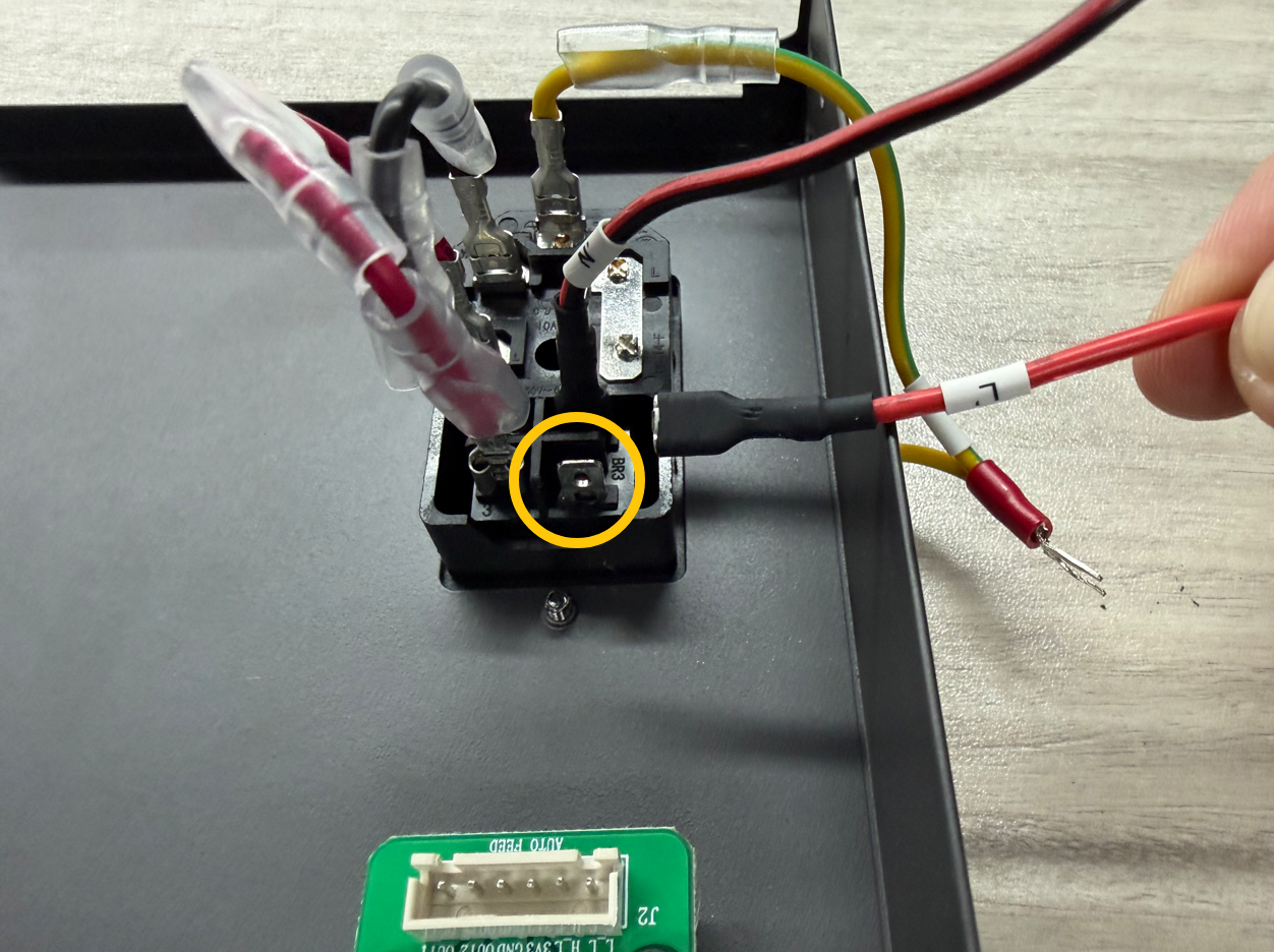
- Connect the L terminal of the power switch wire to the port shown below.
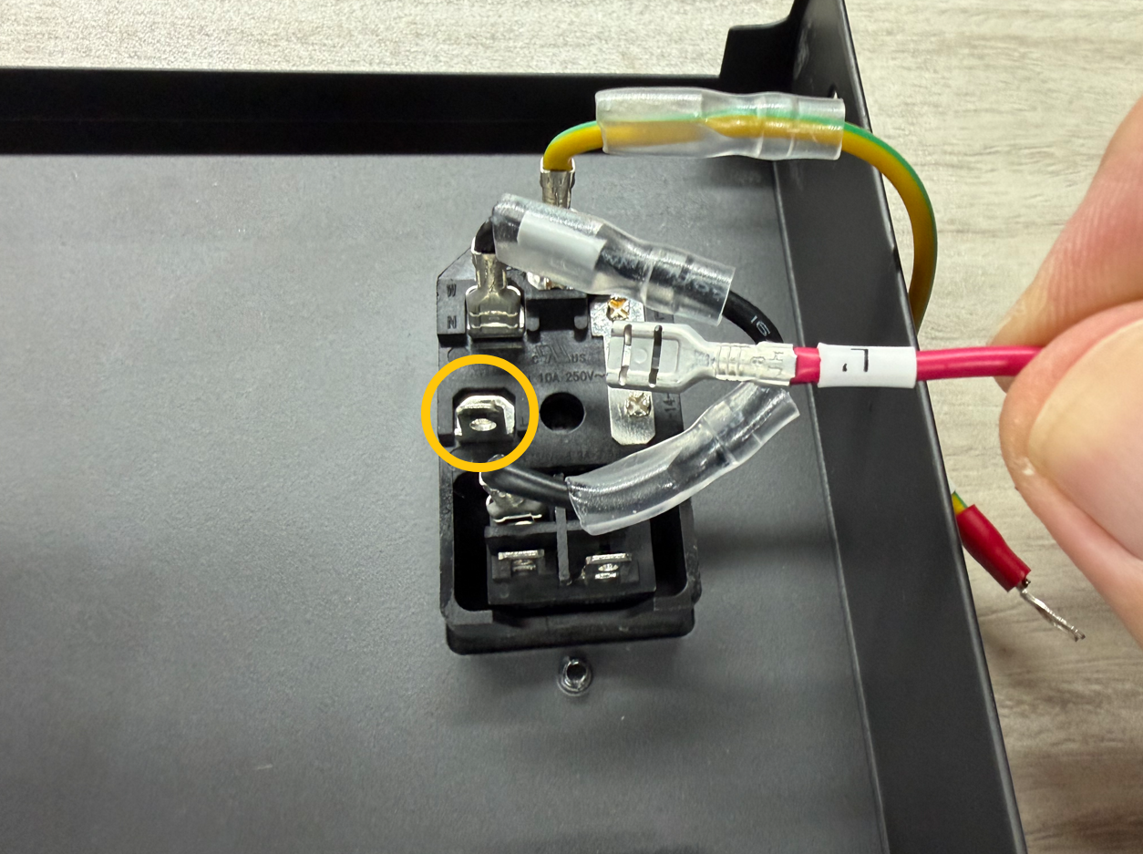
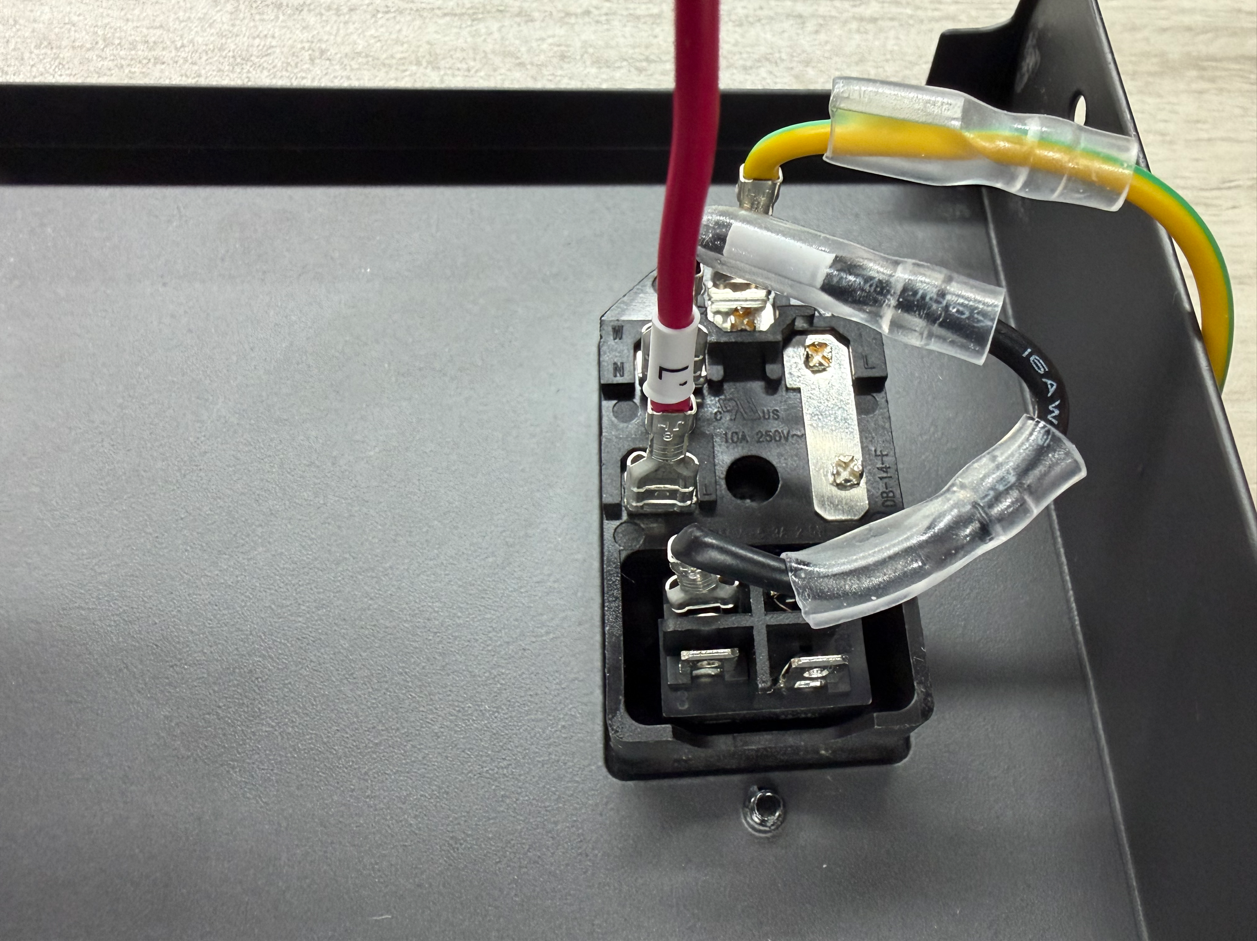
- Connect the other end of the L wire of the power switch wire to the port shown below.
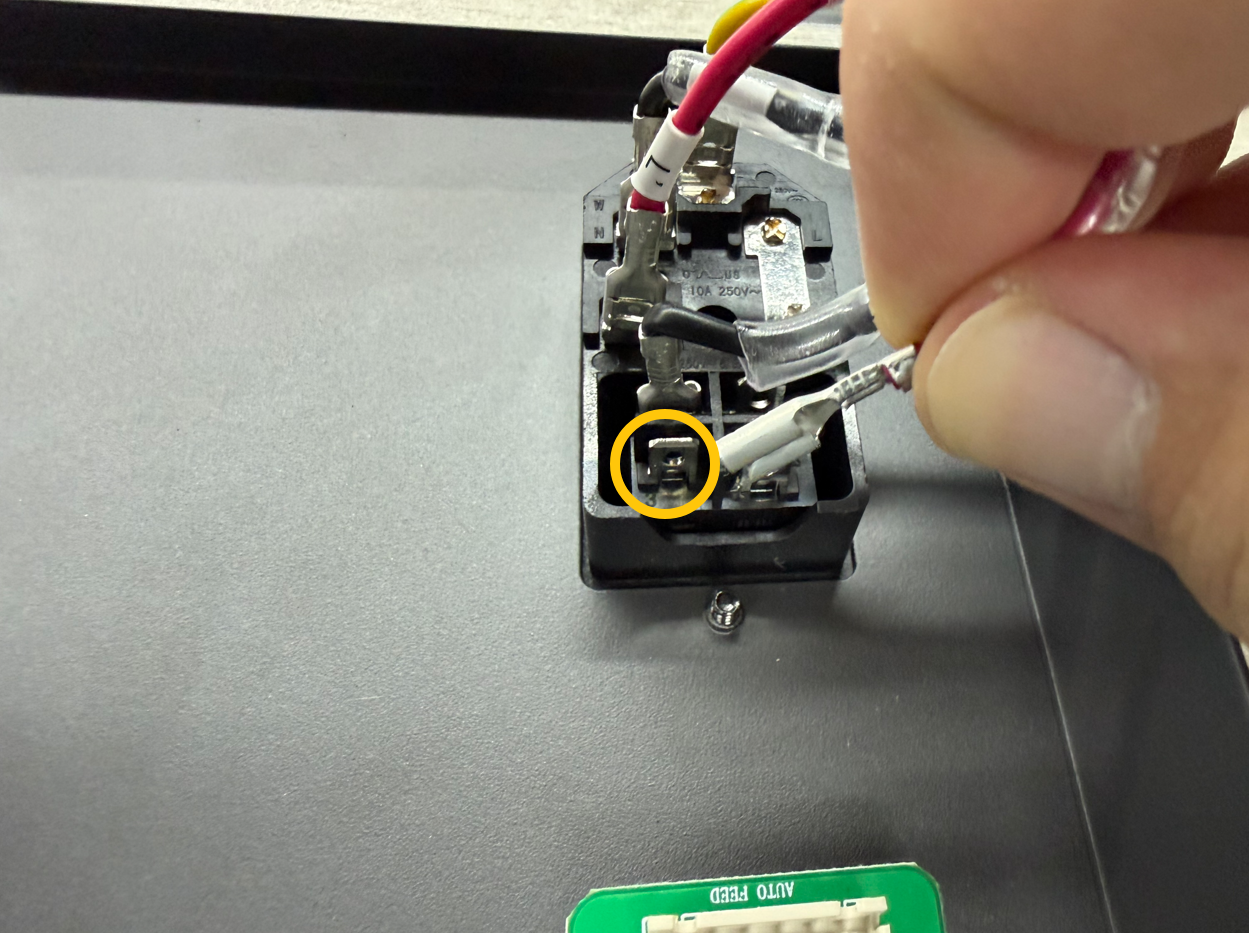
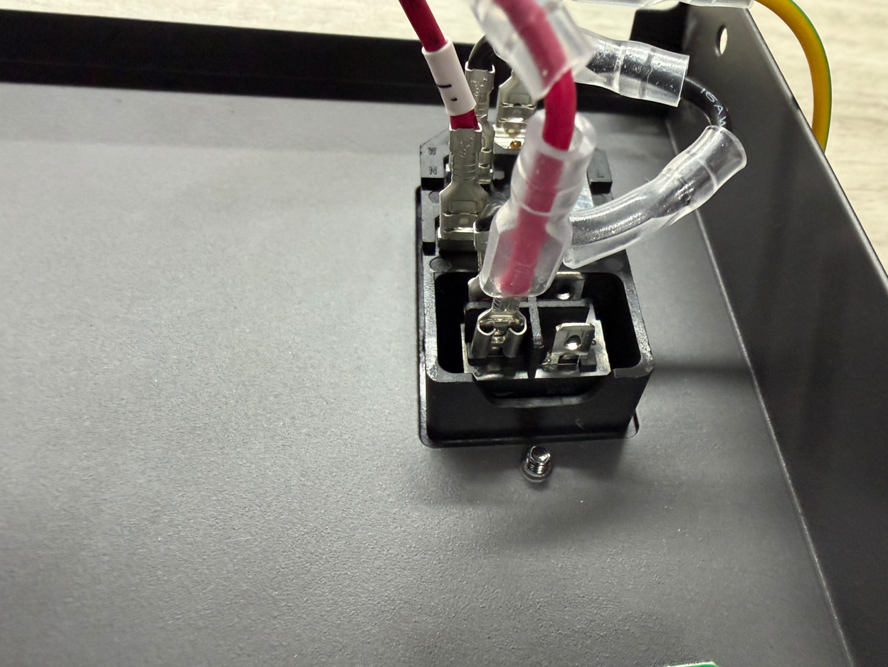
- Insert the N terminal of the AC output wire into the port shown below.
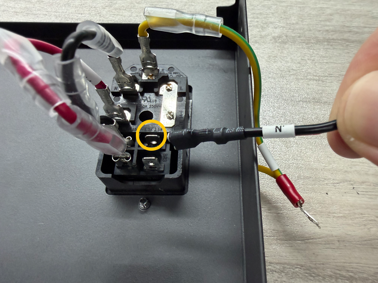

- Insert the L terminal of the AC output wire into the port shown below.
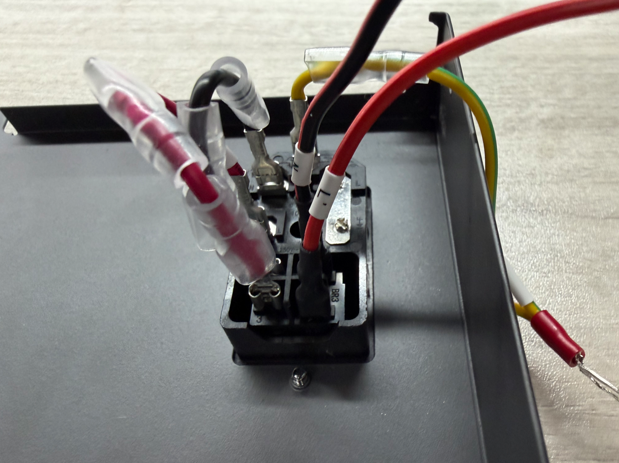
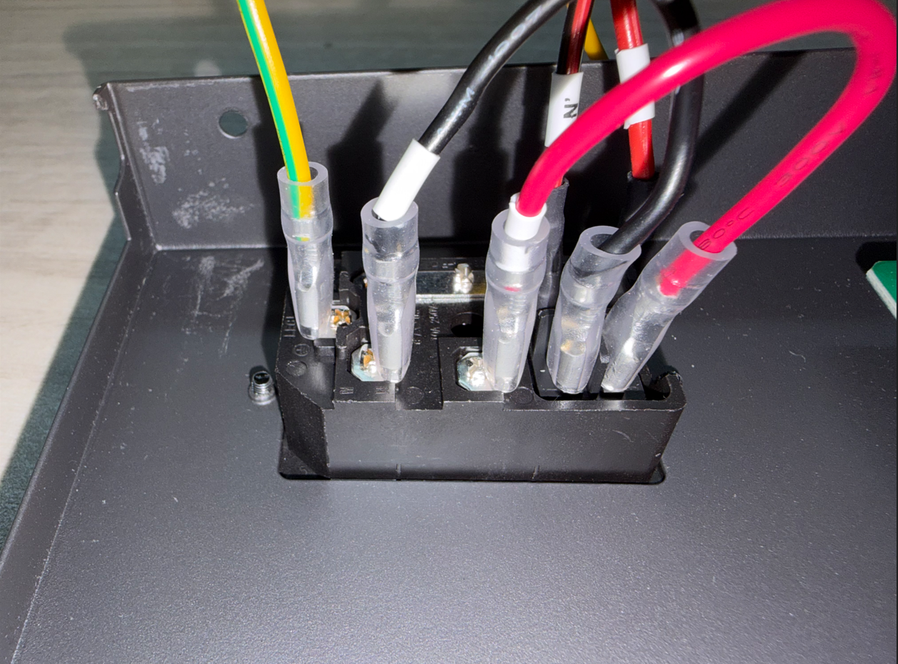
- Pull the insulation sleeve down until it completely covers the wire terminal.
Note: After completing the above steps, check the following:
1.Confirm that all wires are connected to the correct ports.
2.Gently pull each quick-connect terminal to ensure that it does not come loose.
3.Confirm that the insulation sleeves completely cover the metal terminals.
4.Confirm that no wires, copper strands, or metal terminals are abnormally exposed.
5.Confirm that the wires are not pinched by the rear panel or excessively bent.

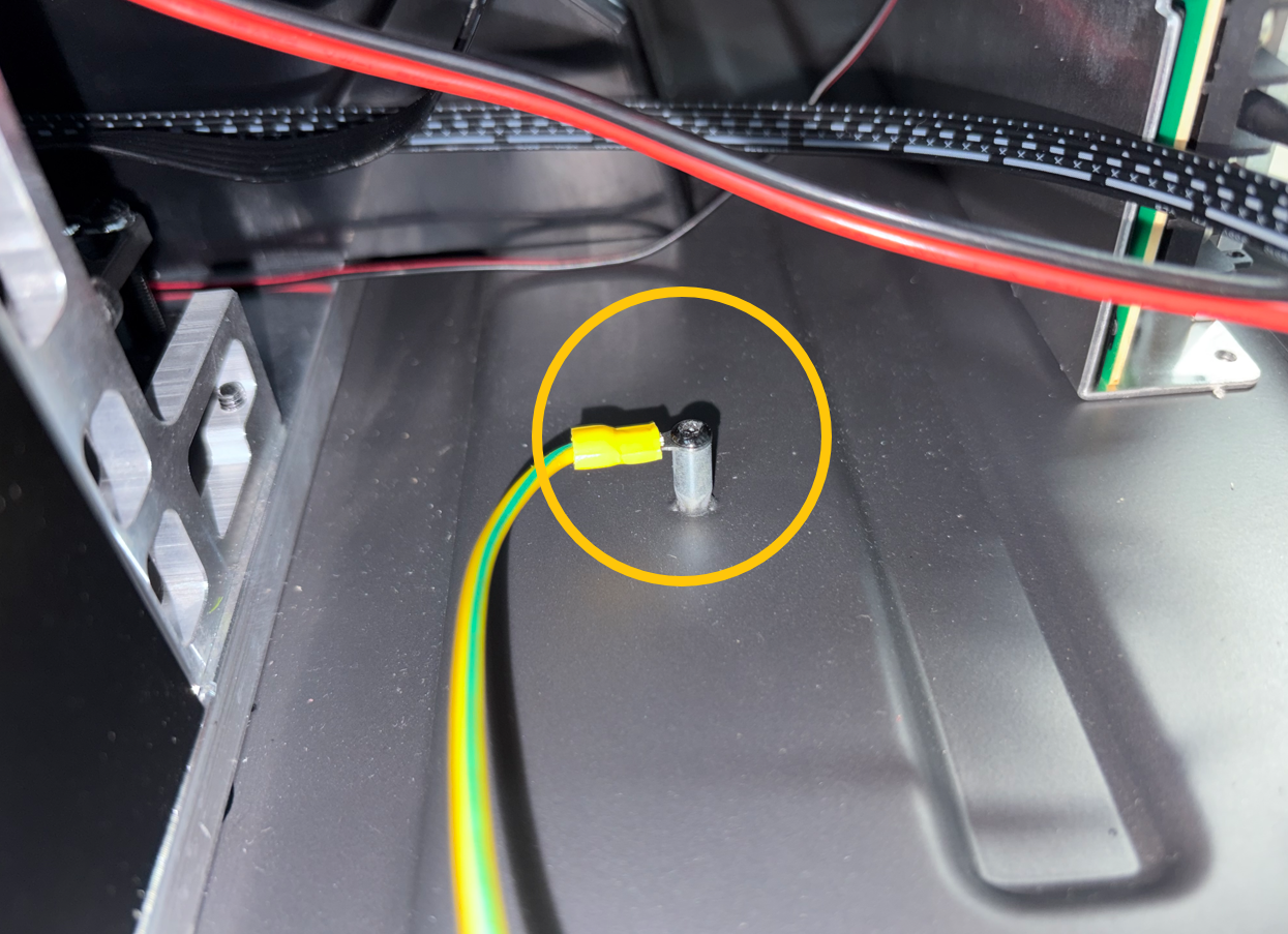
¶ Connect the Ground Wire
Connect the ground wire terminal to the base, then tighten the screw securing the terminal.
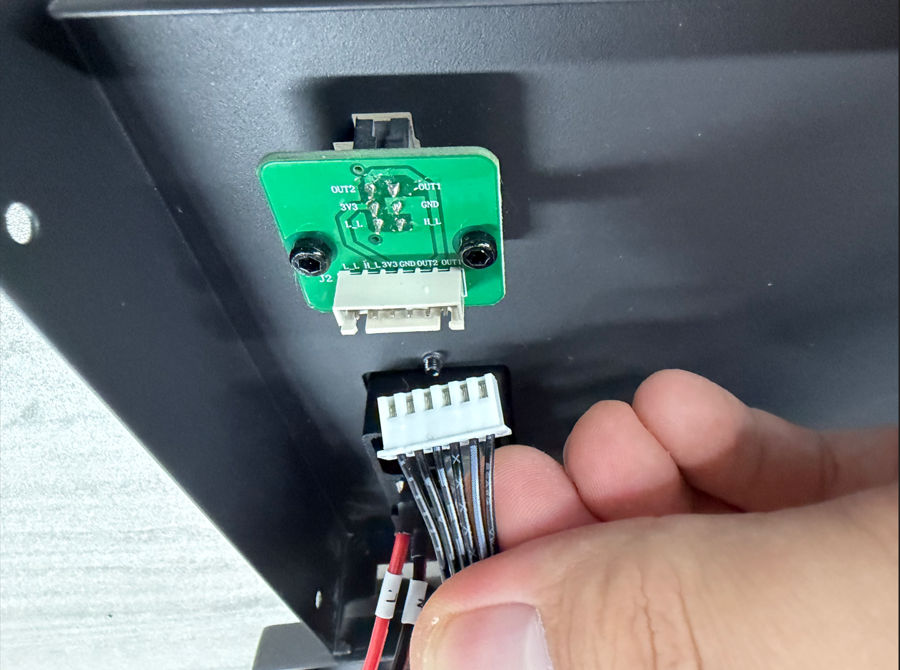
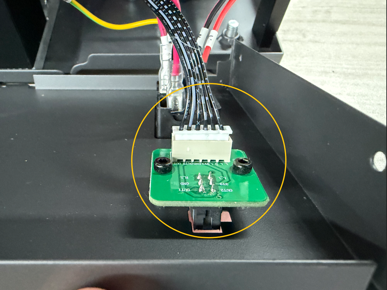
¶ Connect the Feeder Cable Connector
Connect the feeder cable connector to its original position.
¶ Install the Rear Panel
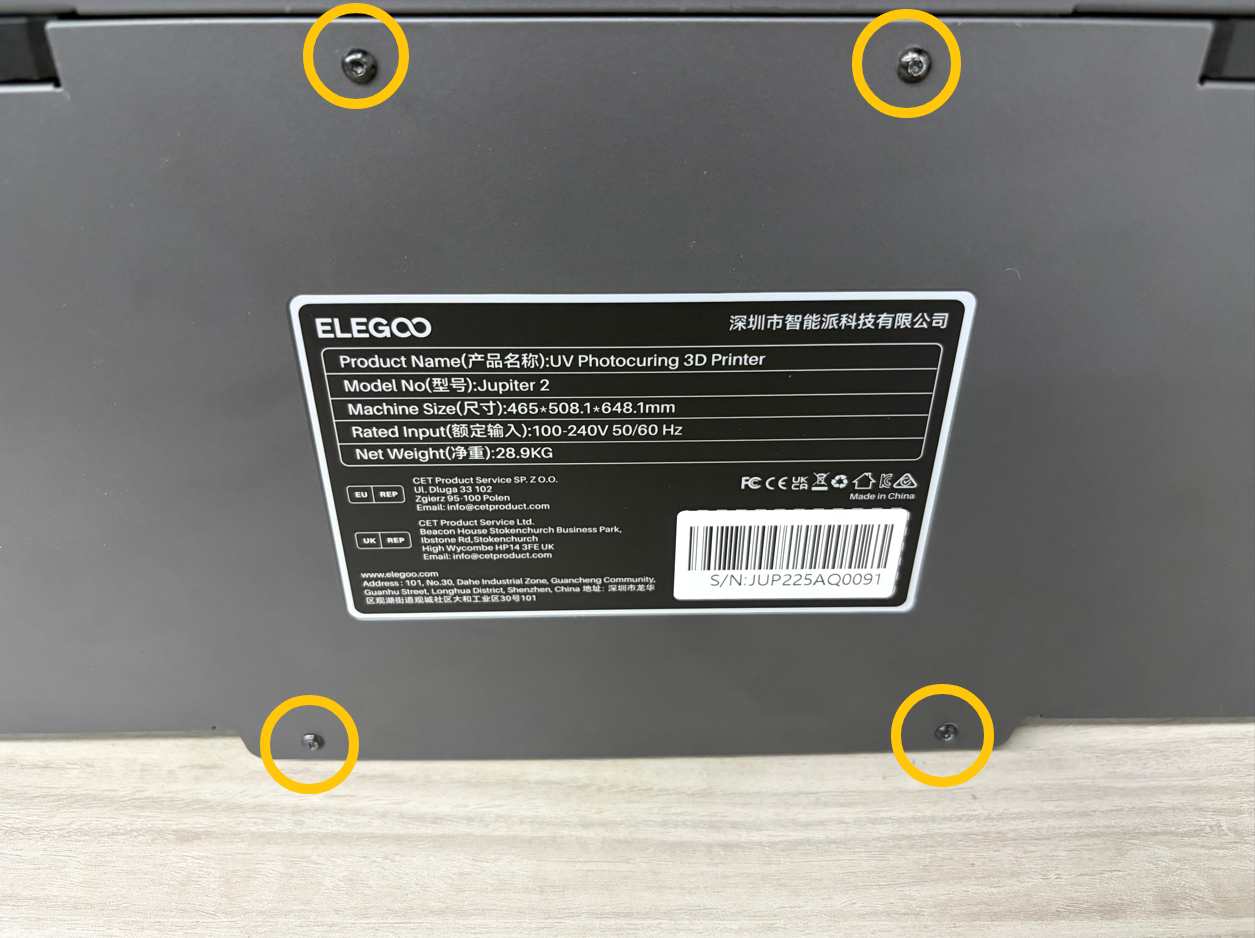
- Hold the rear panel in place and align its holes with the screw holes.
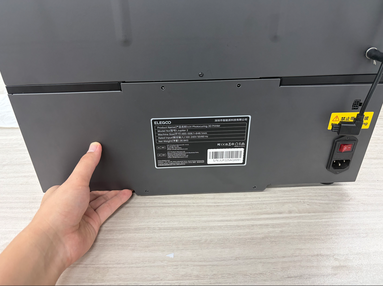
- Tighten the four screws securing the rear panel.
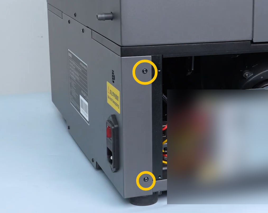
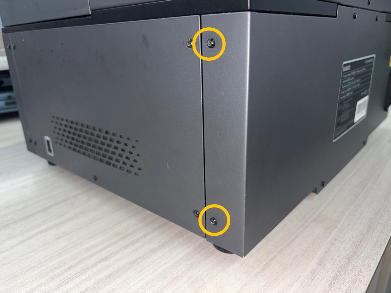
- Tighten the four screws on both sides of the rear panel.
¶ Connect the Automatic Resin Feeding Connector
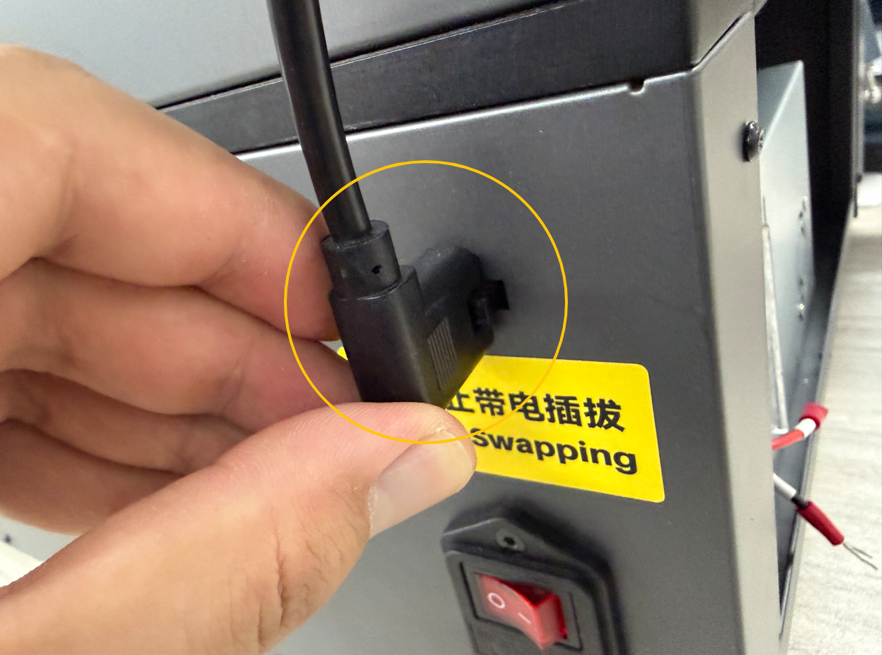
Connect the Automatic Resin Feeding connector to its original position.
¶ Connect the Power Supply Wire Terminals
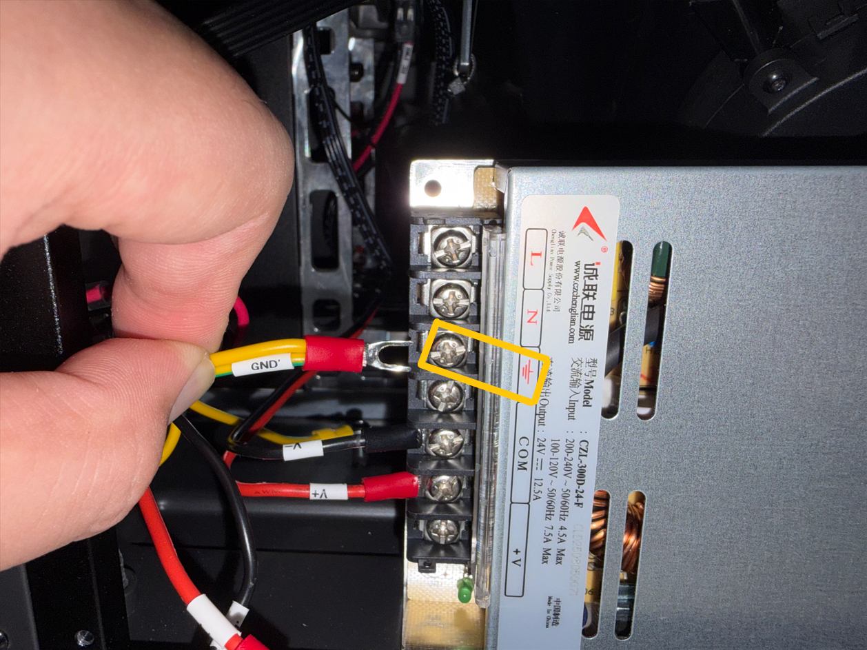
- Connect the GND terminal to the power supply ground terminal, and tighten the screw securing the terminal.
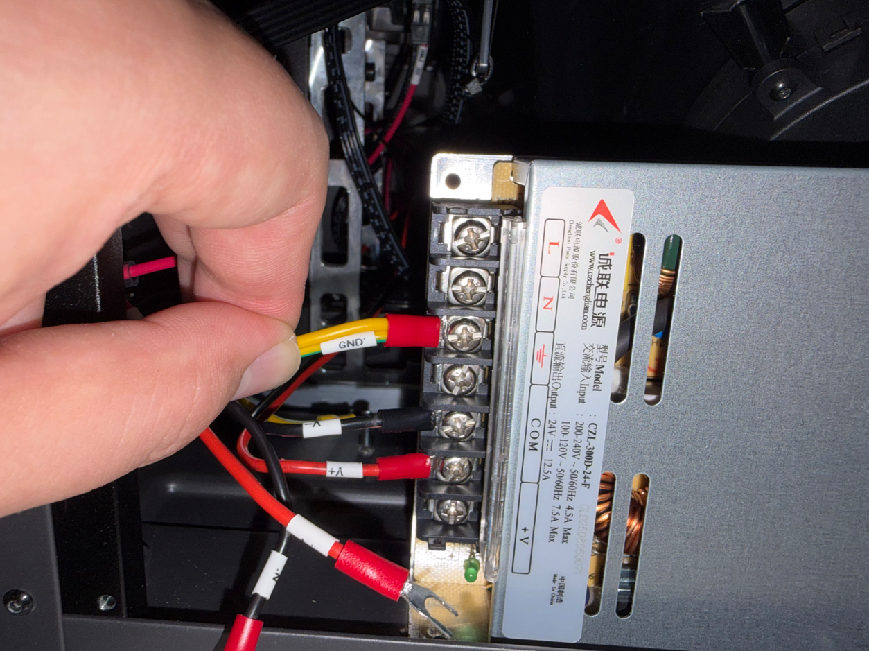
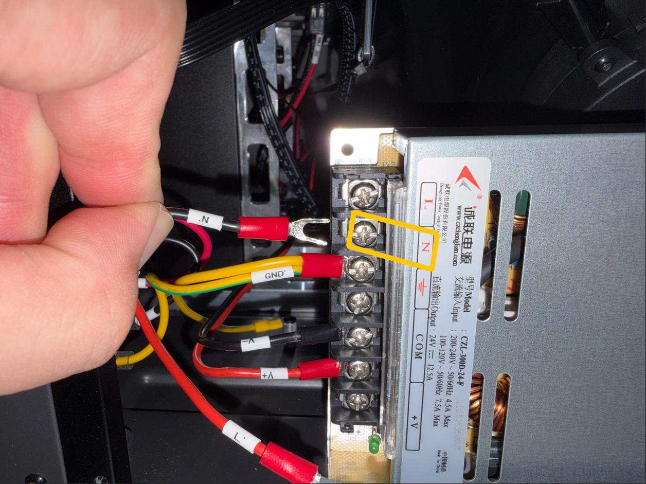
- Connect the N terminal to the power supply N terminal, and tighten the screw securing the terminal.
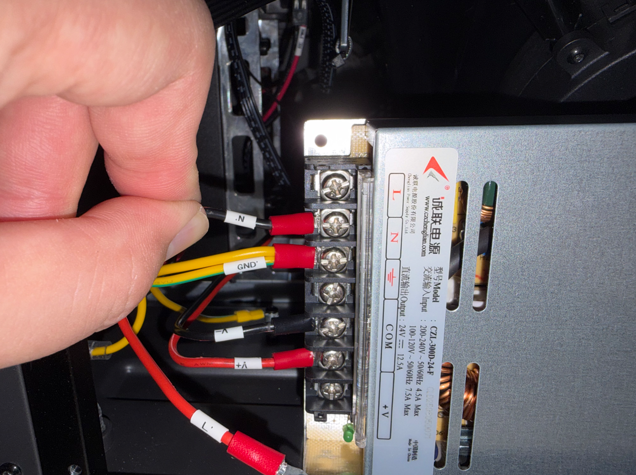
- Connect the L terminal to the power supply L terminal, and tighten the screw securing the terminal.
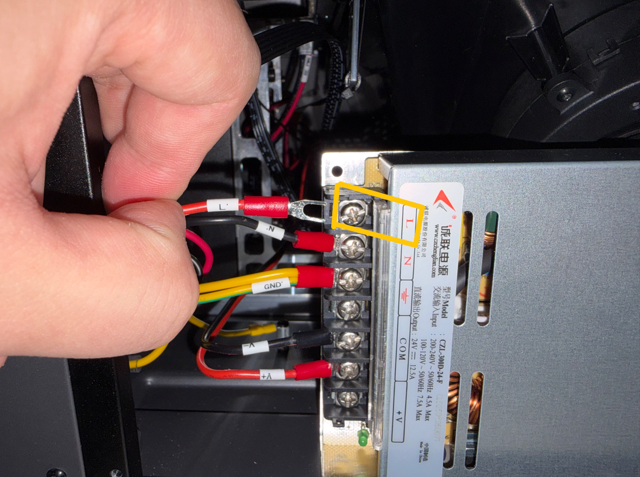
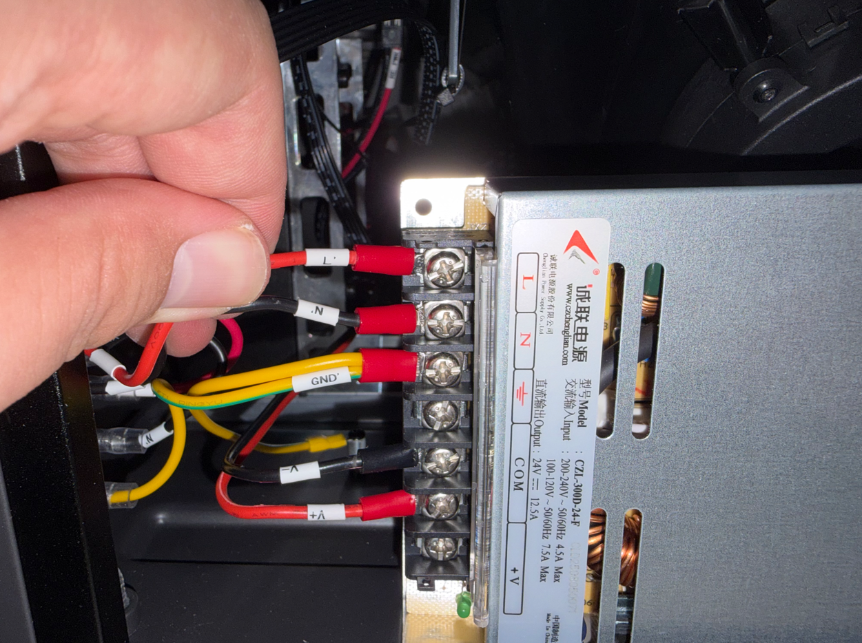
- Confirm that the wiring is correct, then close the power supply cover.
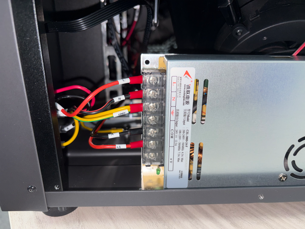
¶ Install the Left Panel
- Place the left panel back into its original position.
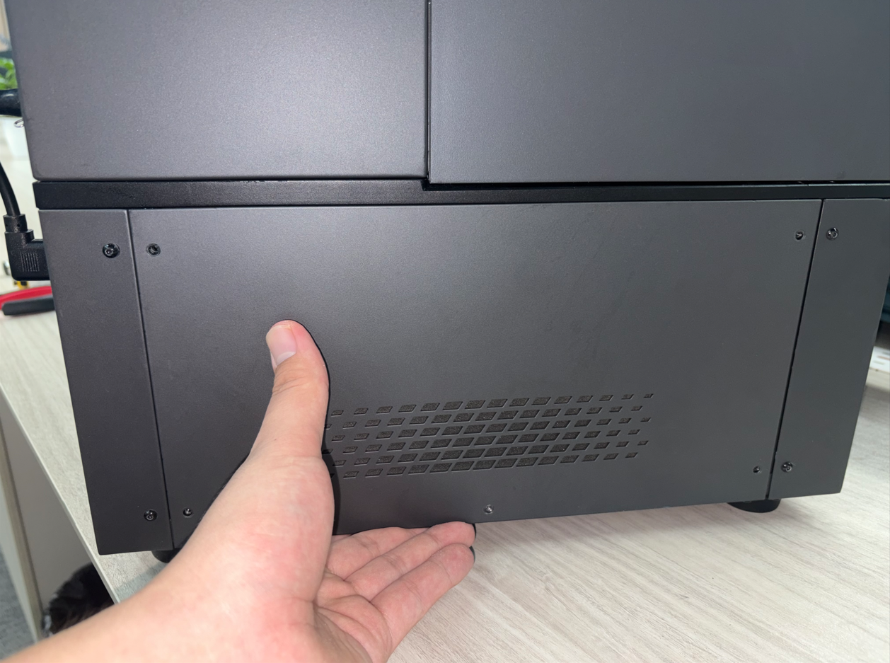
- Tighten the five screws securing the left panel.
¶ Verification
- Make sure the power switch is turned off.
- Plug in the power cord.
- Turn on the printer's power switch.
- Confirm that the power switch indicator lights up and the touchscreen turns on. The power switch replacement is complete.
- If the printer fails to start normally, produces an unusual odor or abnormal noise, or exhibits any other abnormality, immediately turn off the power switch and unplug the power cord. Then, recheck the wiring.
¶ Help us improve
If you have any ideas about the wiki pages, please let us know via ELEGOO official feedback channel