¶ Preparation
- Turn off the printer using the Power Switch and unplug the power cable.
¶ Required tools and parts:
- New Magnetic Female Connector PCB
- 3.0 mm hex screwdriver
- Cutting pliers
- Tweezers
- Alcohol
¶ Disassembly
¶ 1. Remove the Build Plate
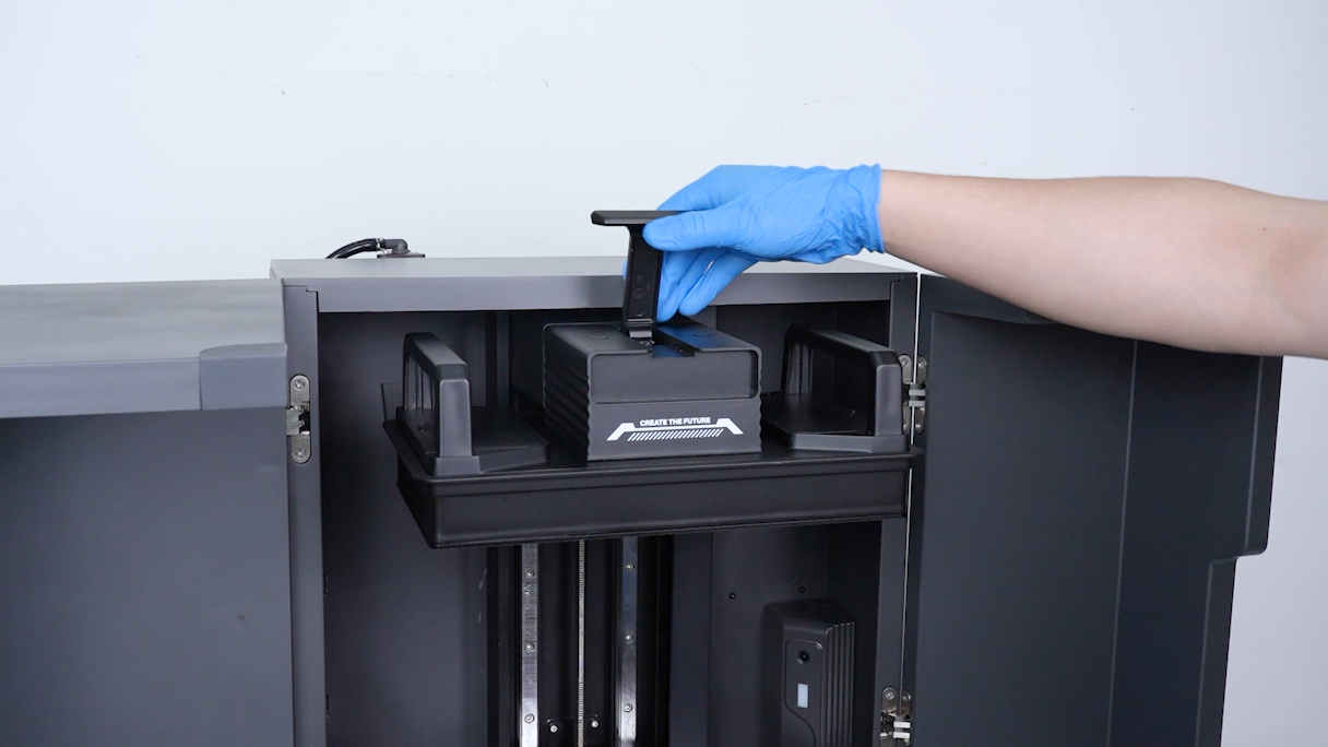
Lift the latch and remove the Build Plate.
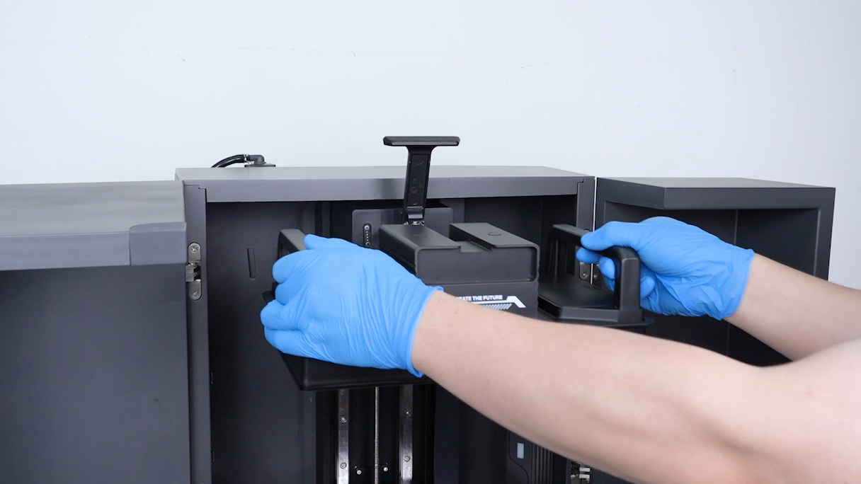
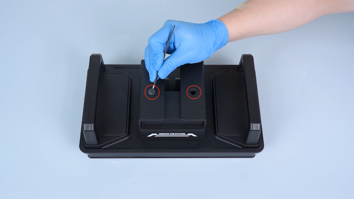
Use tweezers to pry open the upper plug on the platform housing and remove it.
¶ 2. Remove platform housing
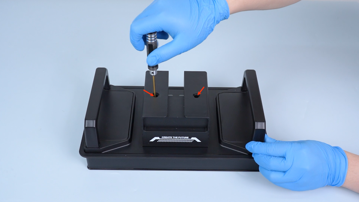
- Use a 3.0 mm hex screwdriver to remove the two screws securing the platform housing.
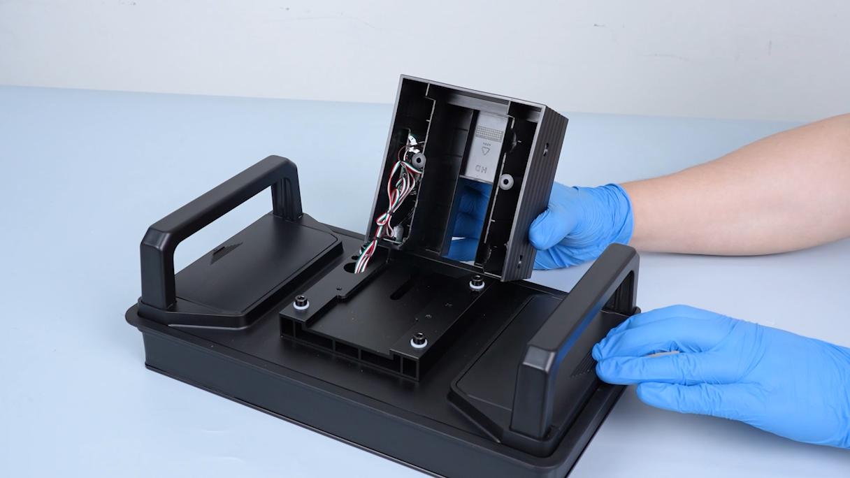
- Open the platform assembly.
¶ 3. Remove magnetic female PCB
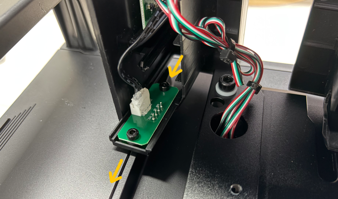
Pull out the Magnetic Female Connector PCB from the platform housing slot.
¶ 4. Disconnect cables
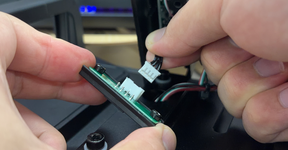
- To prevent connector loosening, hot glue is applied on the rear side of the PCB connector.
- The hot glue is removable. Use cutting pliers or tweezers to remove it.
- If it is difficult to remove, apply alcohol and wait 2–3 minutes for easier removal.
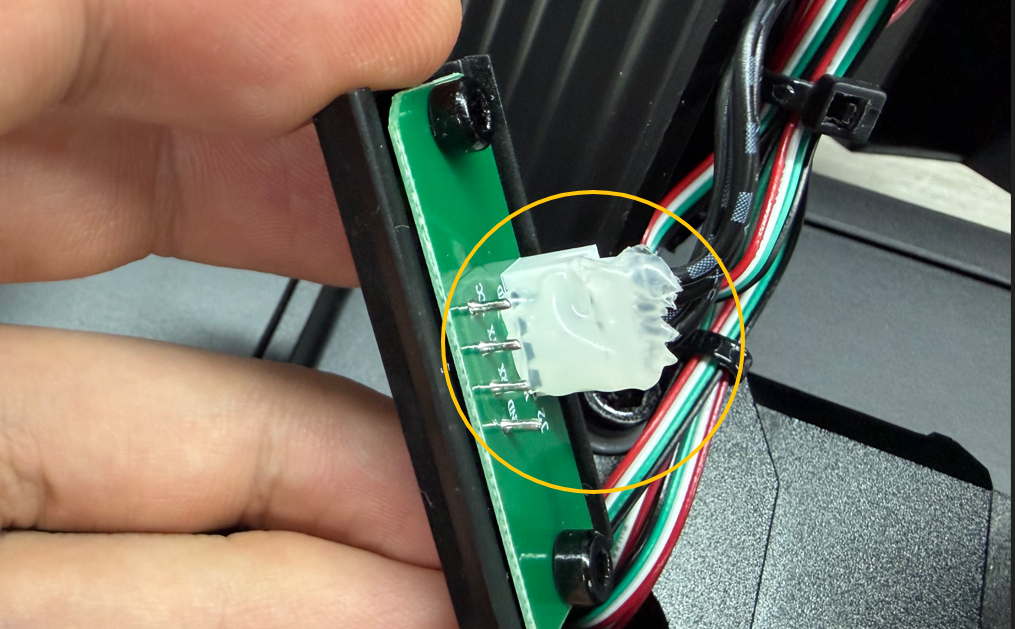
- Disconnect the cable plugs.
¶ Installation
¶ 1. Connect cables
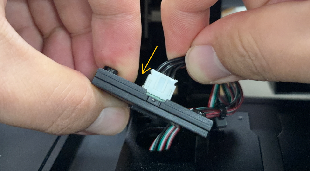
- Connect the cable plugs to the back of the Magnetic Female Connector PCB.
¶ 2. Install PCB
- Insert the Magnetic Female Connector PCB into the platform housing slot.
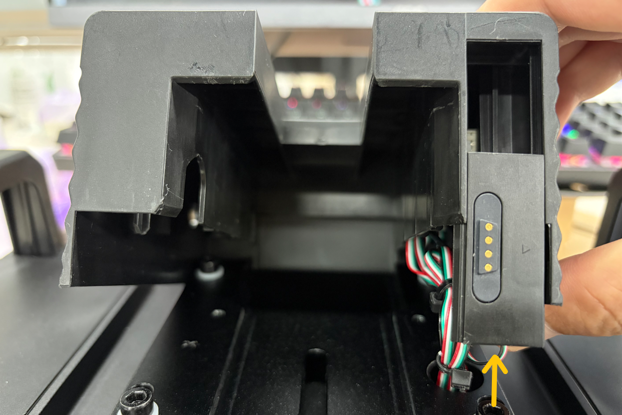
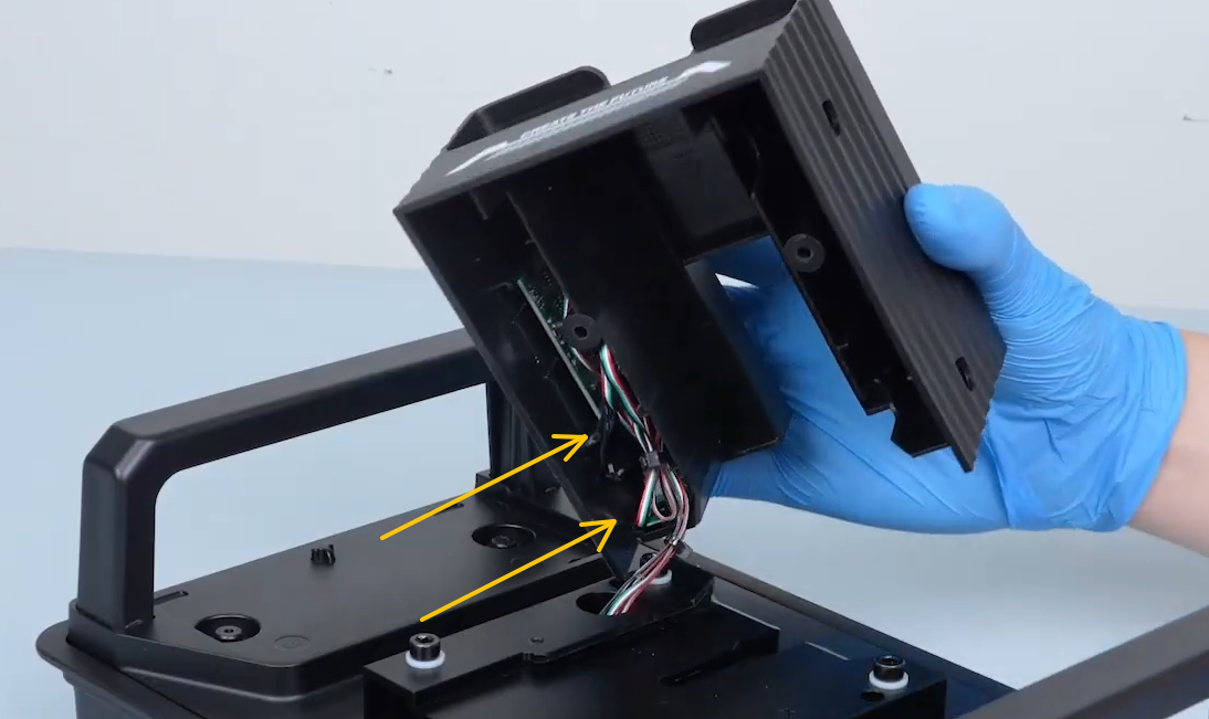
- Route the cable into the cable channel.
¶ 3. Reinstall platform housing
- Place the platform housing back into position.
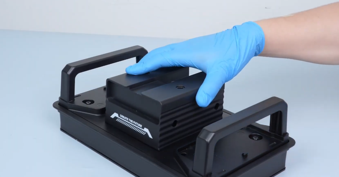
- Tighten the two screws using a 3.0 mm hex screwdriver.
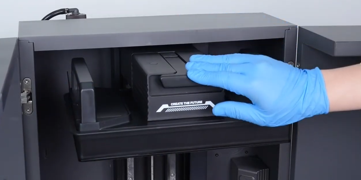
¶ 4. Reinstall Build Plate
- Place the Build Plate back into position.
- Lift the latch and lock it securely.
¶ Verification
- Plug in the power cable and turn on the printer using the Power Switch.
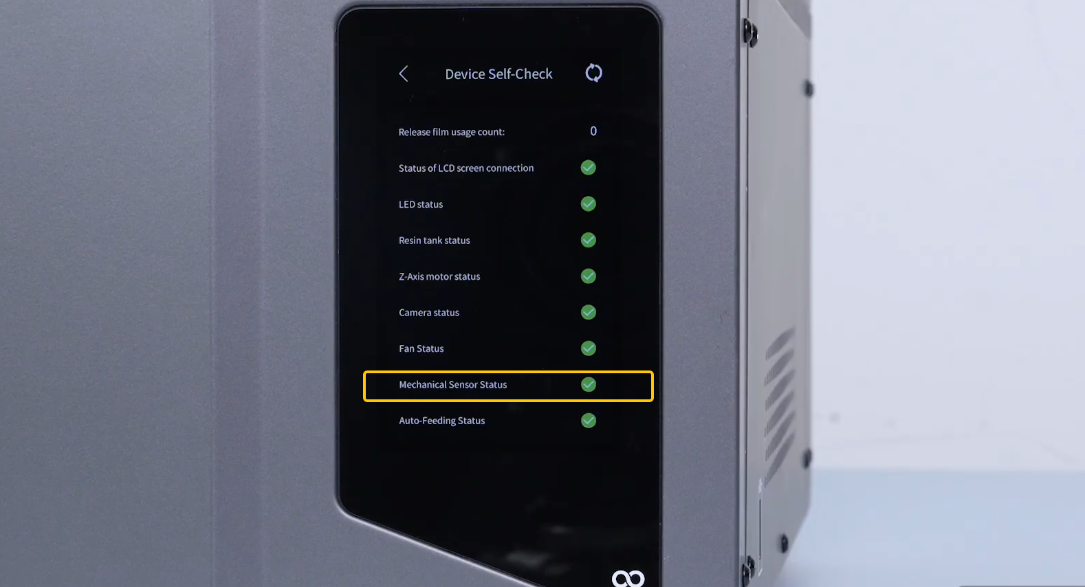
- Check the Touch Screen and confirm that the force sensor passes self-test.
- Replacement is complete.