¶ Tools and Materials
-
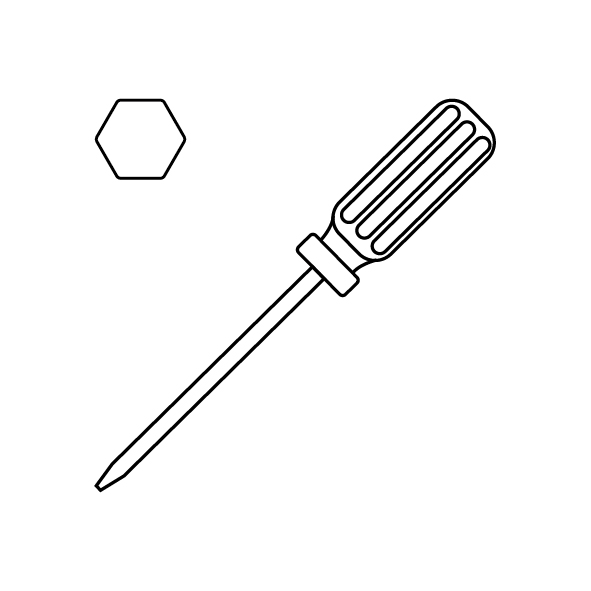
A 2.0 mm Allen key
-
A 2.5 mm Allen key
-
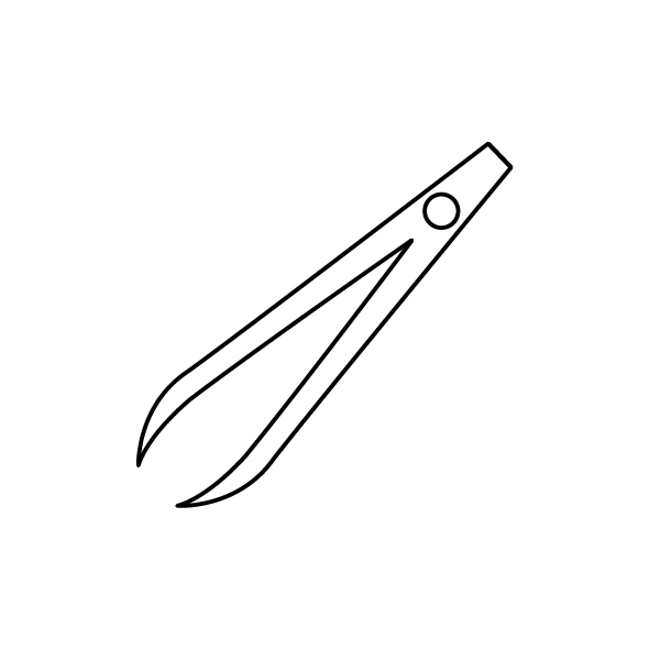
A pair of tweezers
-
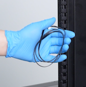
A new Z-axis limit switch cable
¶ Tutorial Video
¶ Instruction
¶ Preparation
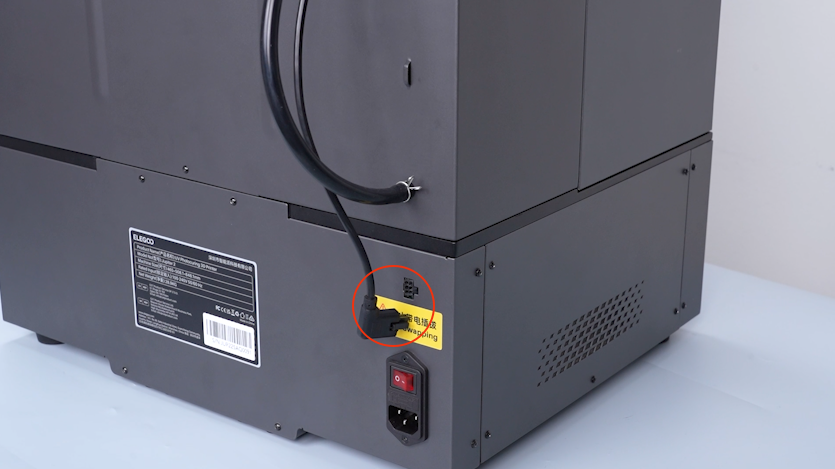
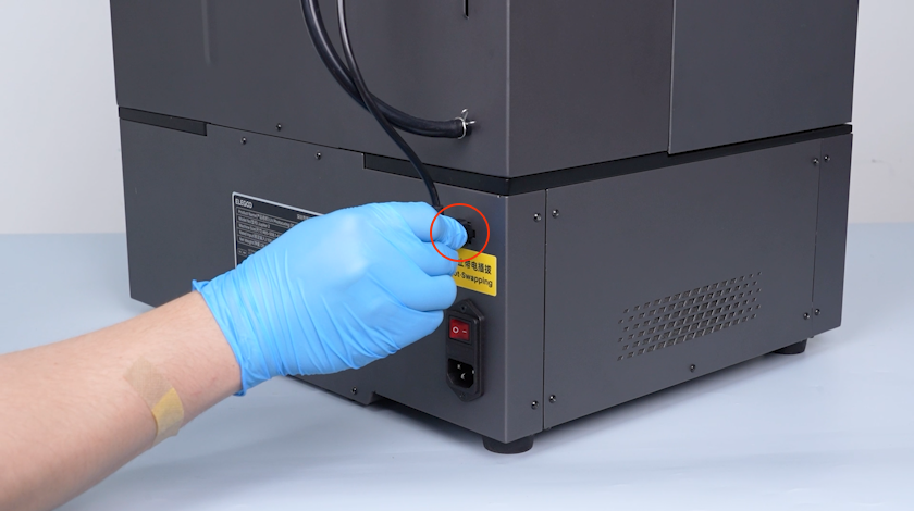
Turn the power switch OFF (symbol "〇") and unplug the power supply cable.
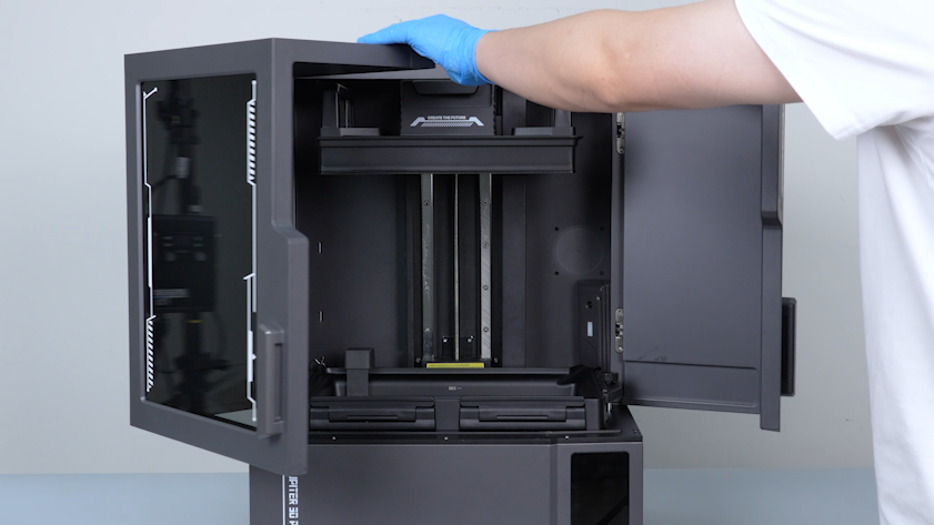
¶ Remove the right cover, build plate, resin tank
-
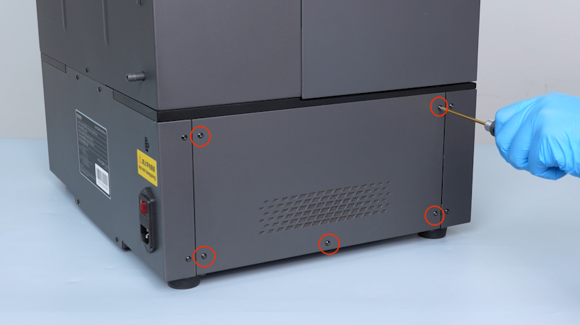
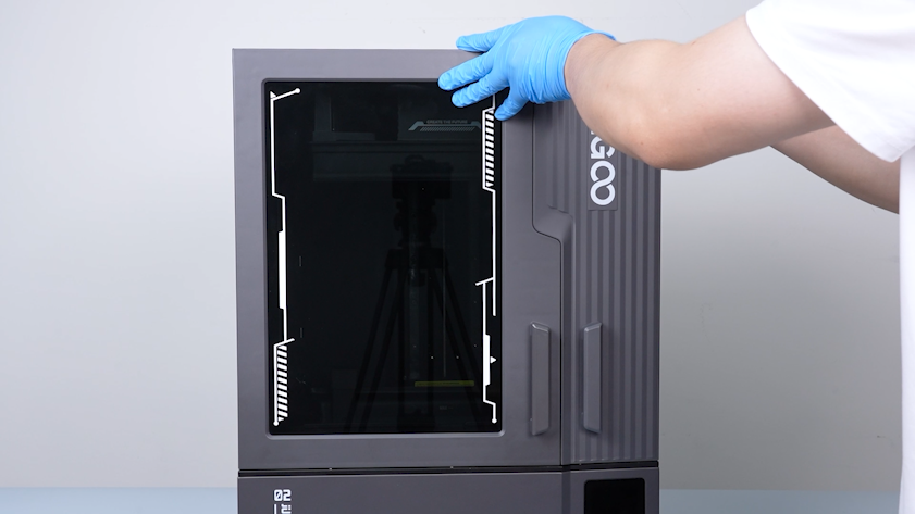
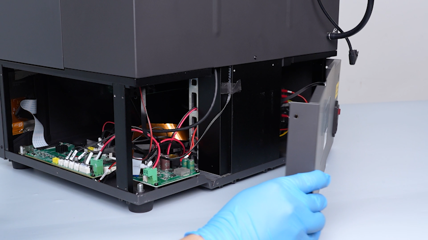
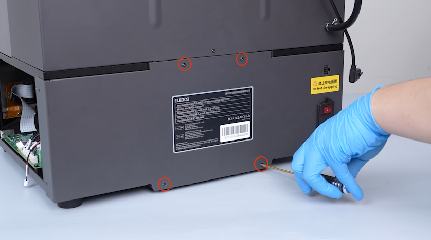
Release and remove the five screws securing the right cover with a 2.0 mm Allen key and remove the right cover.
-
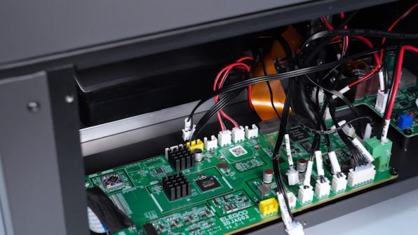
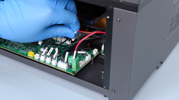
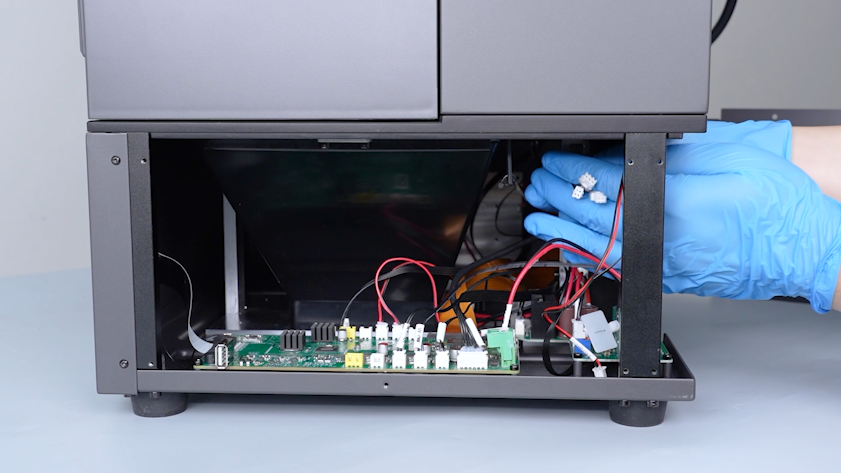
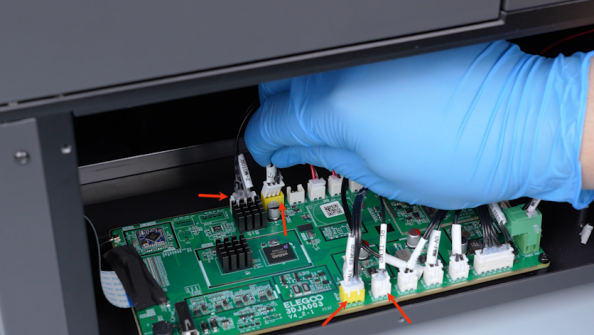
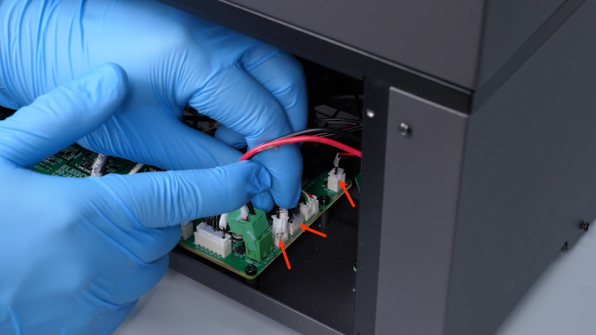
Unplug the cables on the motherboard.
-
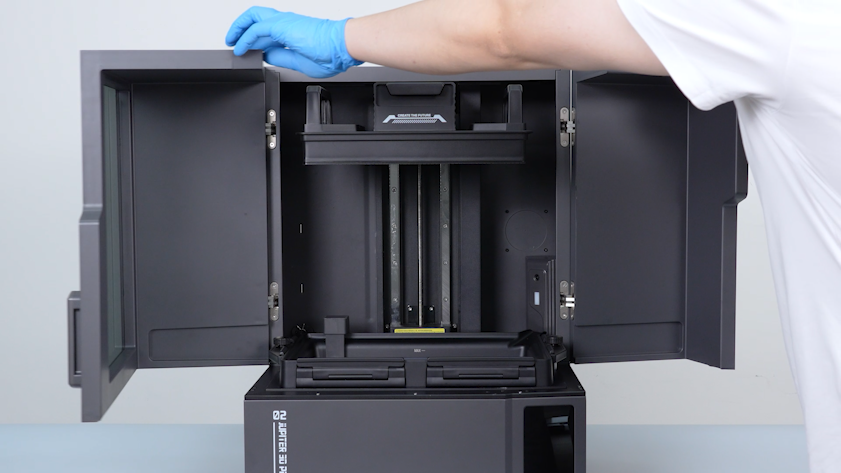
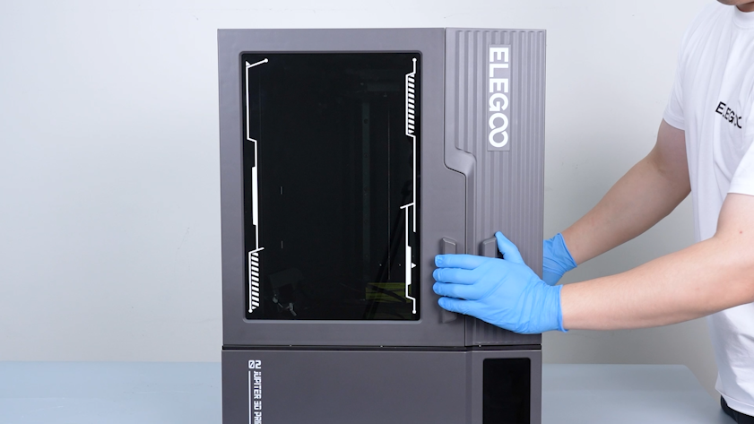
Open the front door.
-
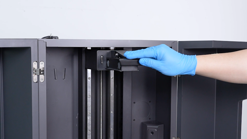
Release the snap.
-
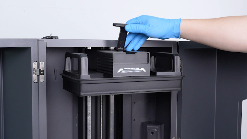
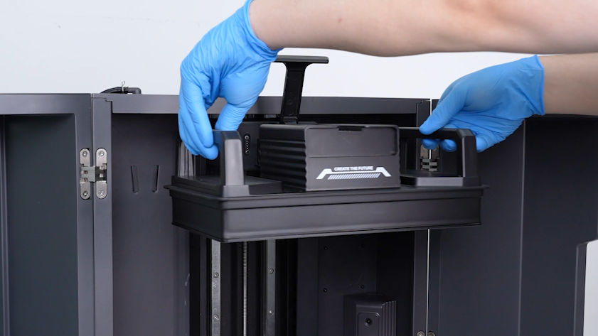
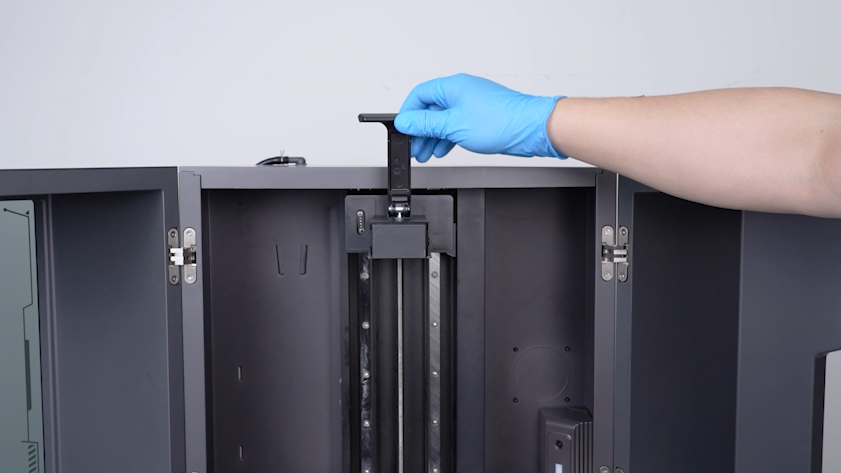
Remove the build plate.
-
Restore the snap of the build plate.
-
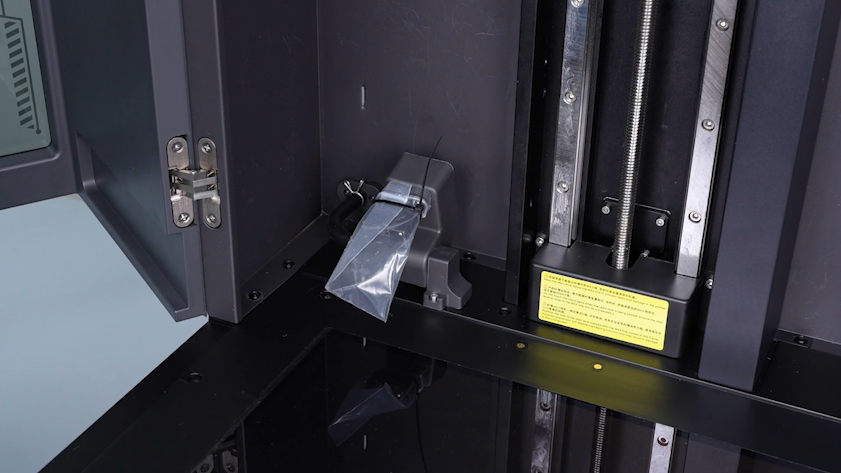
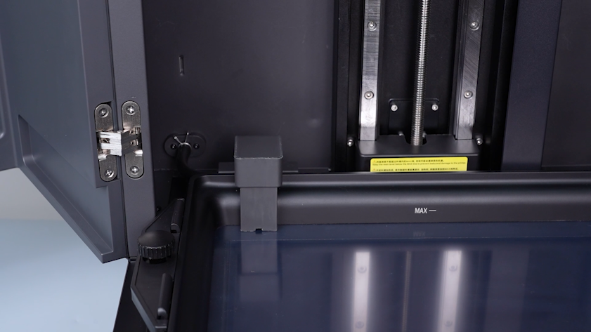
Lift the automatic resin feeding inlet.
-
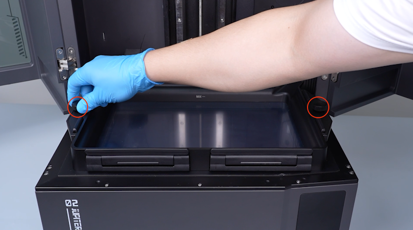
Remove the two knob screws.
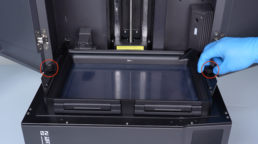
-
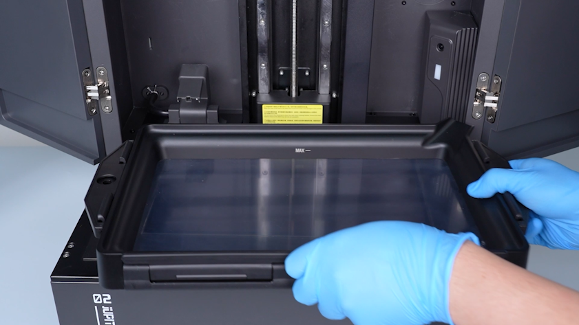
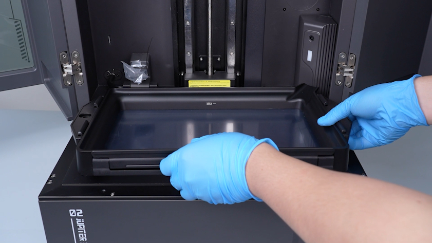
Remove the resin tank.
-
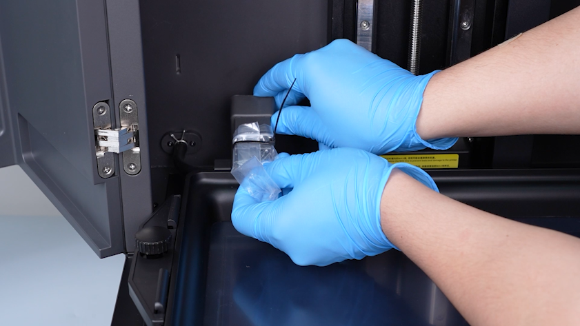
Seal the inlet with a bag and a cable tie to avoid the resin drips.
¶ Remove enclosure and back cover
-
Release and remove the four screws securing the left side of the enclosure with a 2.5 mm Allen key.
-
Release and remove the four screws securing the right side of the enclosure with a 2.5 mm Allen key.
-
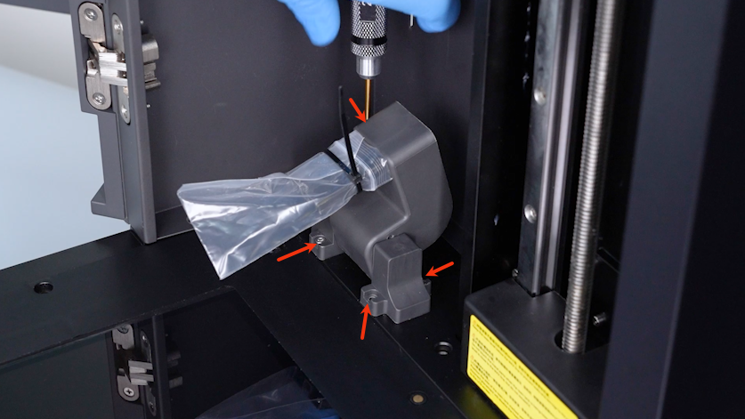
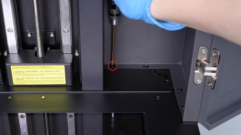
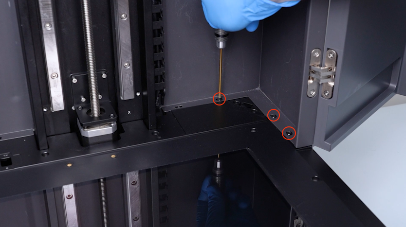
Release and remove the four screws securing the automatic resin feeding inlet with a 2.5 mm Allen key.
-
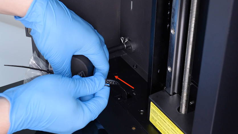
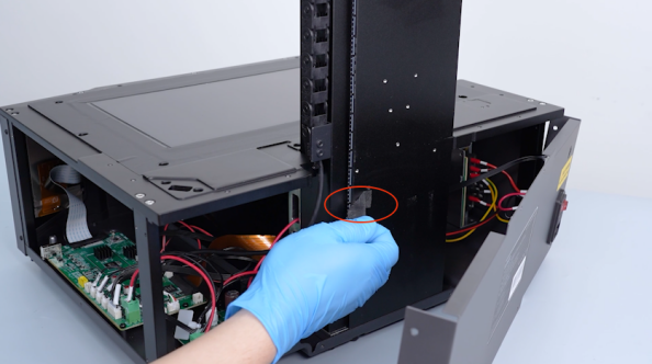
Pull out the cable of the automatic resin feeding inlet from the slot.
-
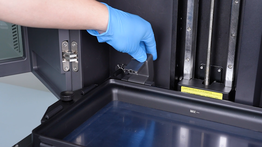
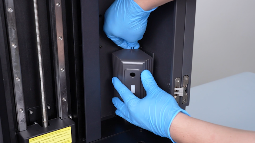
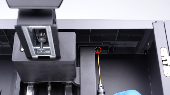
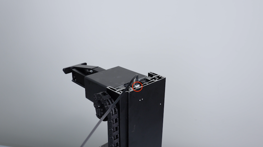
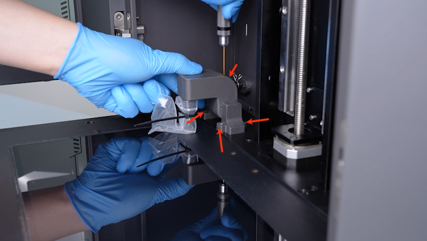
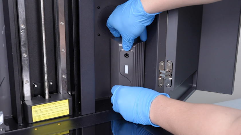
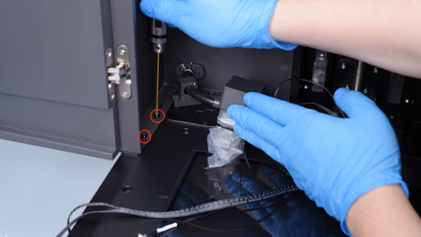
Lift the camera housing with a pair of tweezers.
-
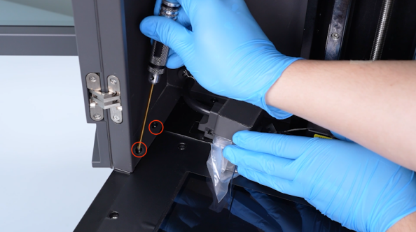
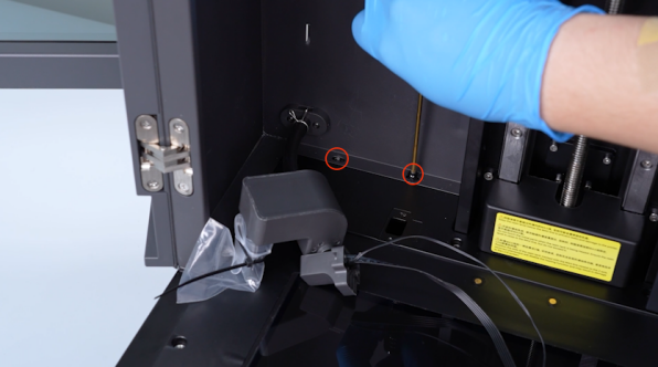
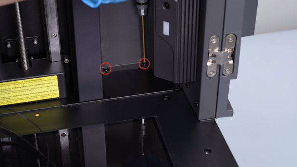
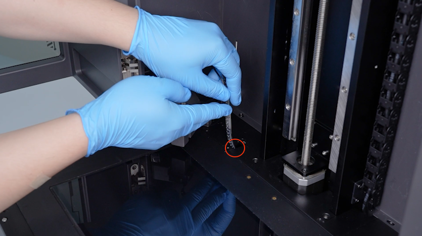
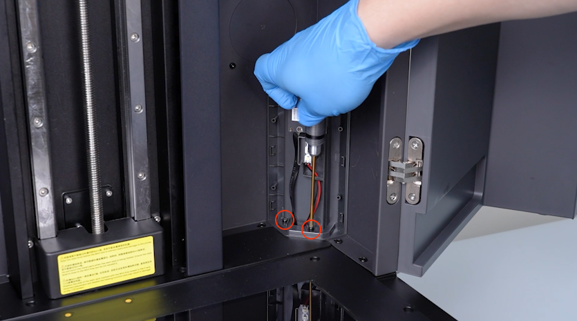
Release and remove the two screws securing the camera holder with a 2.5 mm Allen key.
-
Pull out the camera cable and the LED cable from the slot.
-
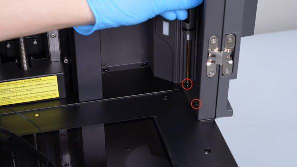
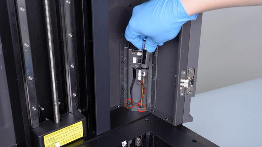
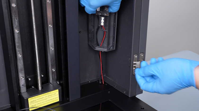
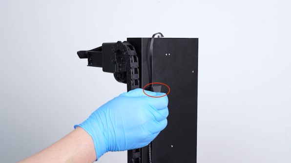
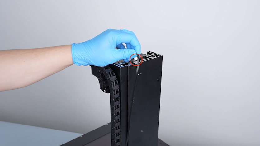
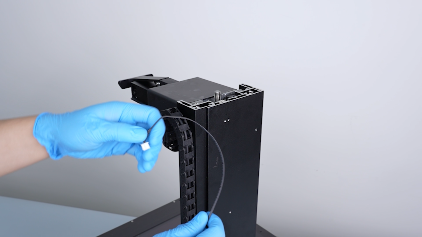
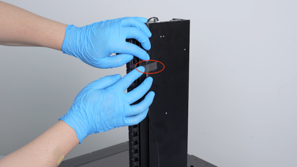
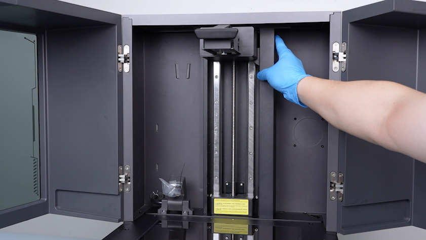
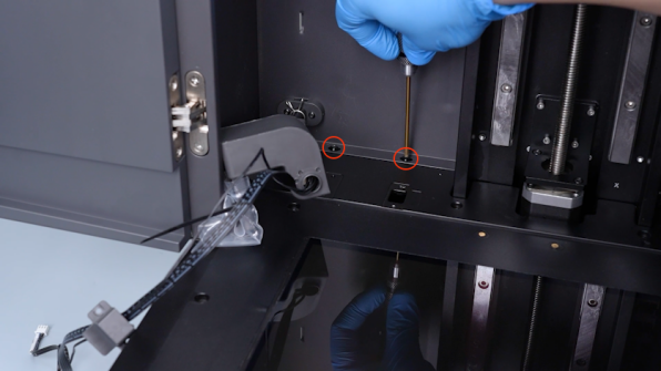
Release and remove the screws securing the tank chain housing with a 2.5 mm Allen key and remove the tank chain housing.
-
Close the front door.
-
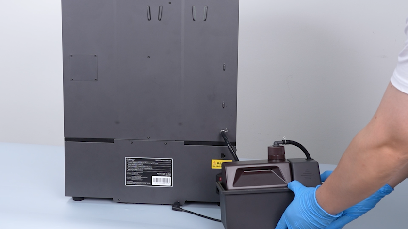
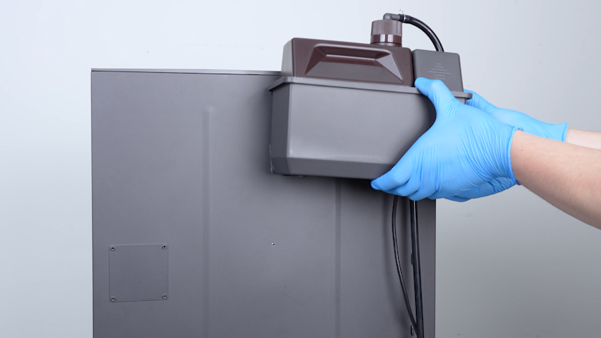
Unplug the cable of the automatic resin feeding inlet.
-
Remove the automatic resin feeding bottle and put it on the table temporarily.
-
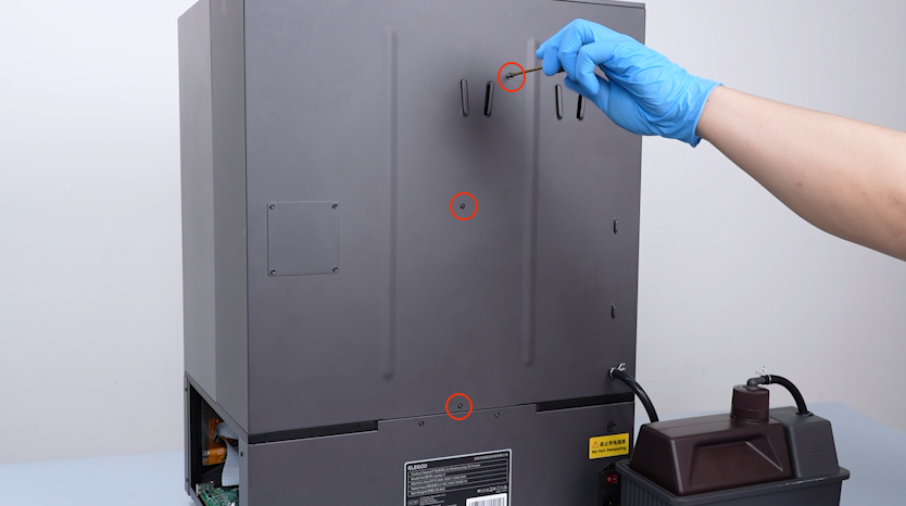
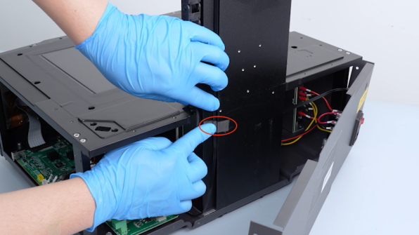
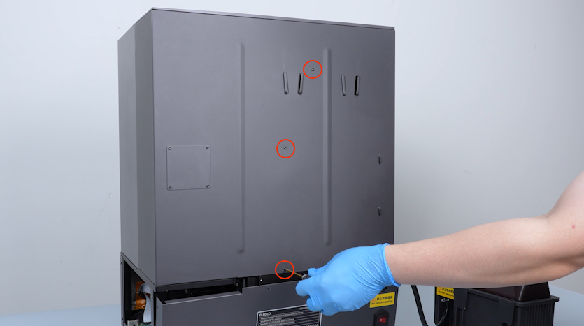
Release and remove the three screws securing the back side of the enclosure with a 2.0 mm Allen key.
-
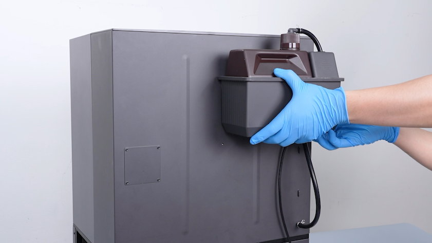
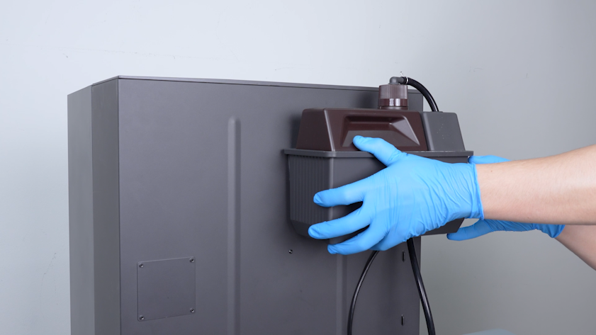
Restore the automatic resin feeding bottle.
-
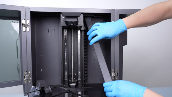
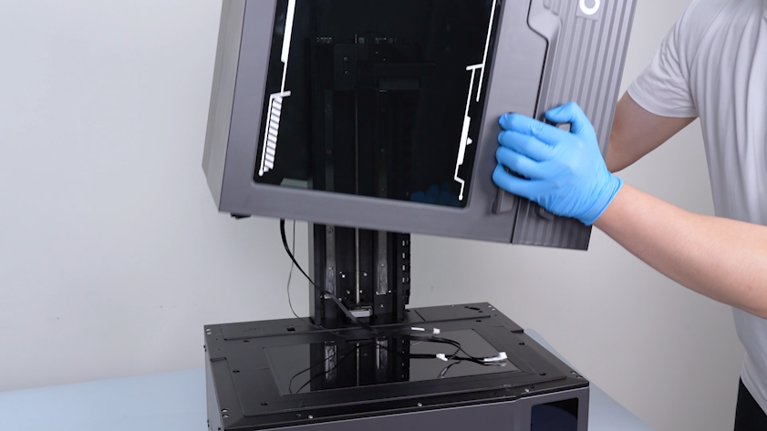
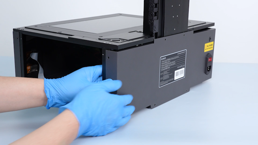
Remove the whole enclosure.
-
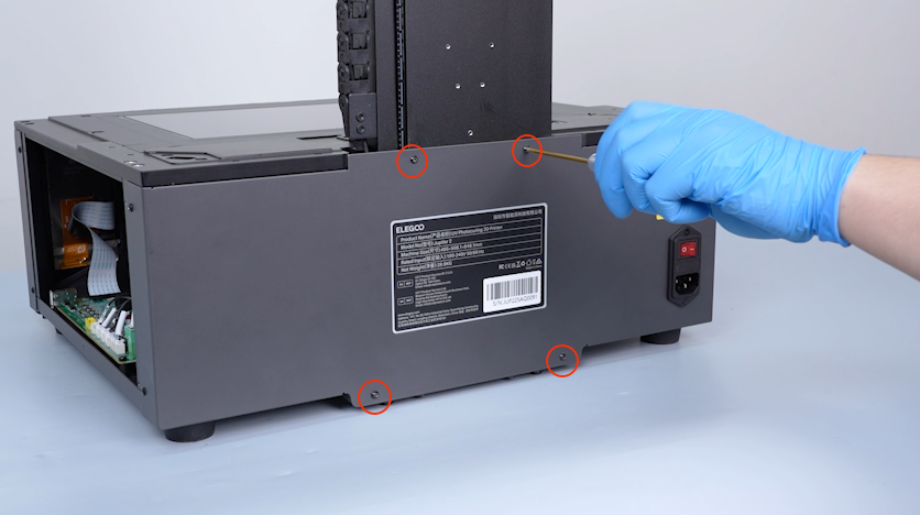
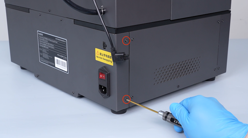
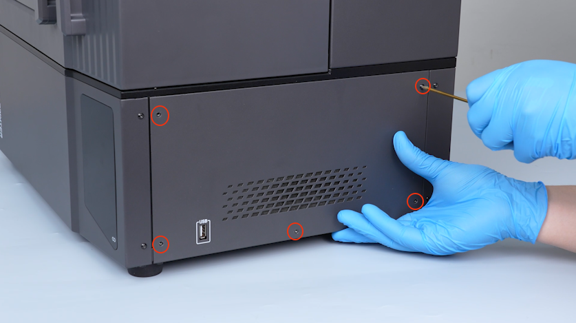
Release and remove the four screws securing the front of the back cover with a 2.0 mm Allen key.
-
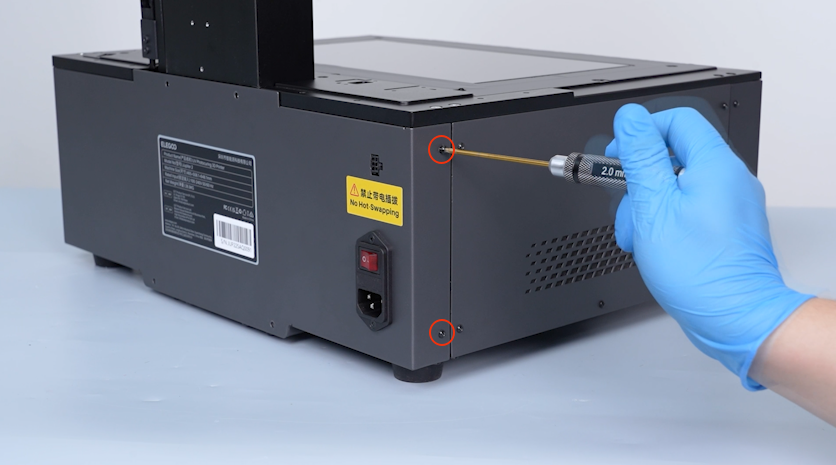
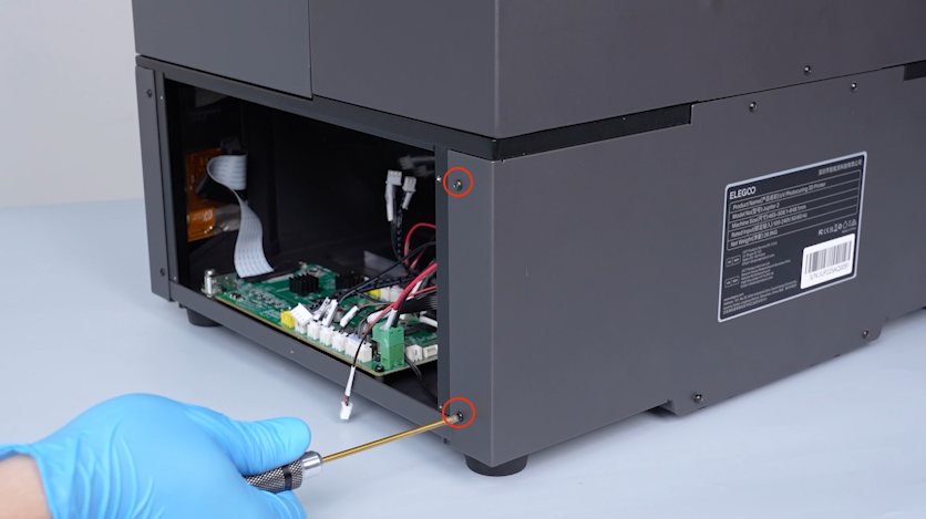
Release and remove the two screws securing the right side of the back cover with a 2.0 mm Allen key.
-
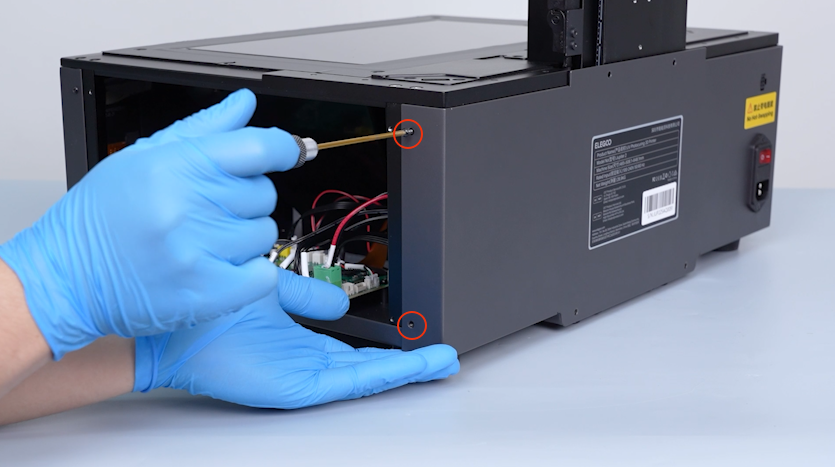
Release and remove the two screws securing the left side of the back cover with a 2.0 mm Allen key.
Note: Hold the back cover when releasing the last screw.
-
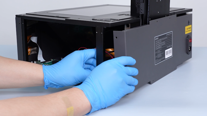
Open the back cover.
¶ Remove the old Z-axis limit switch cable
-
Remove the tape securing the Z-axis limit switch cable.
Note: Keep the tape at hand as it will be reused later.
-
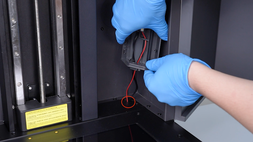
Unplug the cable of the Z-axis limit switch.
-
Remove the old cable of the Z-axis limit switch.
¶ Install the new Z-axis limit switch cable
-
Get the new Z-axis limit switch cable and plug in the Z-axis limit switch cable.
-
Secure the Z-axis limit switch cable with tape.
¶ Install the enclosure and back cover
-
Put the back cover in the installation position.
-
Put the enclosure in the installation position.
-
Remove the automatic resin feeding bottle and put it on the table temporarily.
-
Tighten the three screws securing the back side of the enclosure.
-
Restore the automatic resin feeding bottle.
¶ Install the right cover, build plate and resin tank
-
Open the front door.
-
Pass the cable of the automatic resin feeding inlet through the slot.
-
Tighten the four screws securing the automatic resin feeding inlet.
-
Pass the camera cable and the LED cable through the slot.
-
Tighten the two screws securing the camera holder with a 2.5 mm Allen key.
-
Put the camera housing in the installation position.
-
Put the housing of the tank chain in the installation position.
-
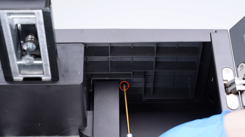
Tighten the screw securing the upper part of the housing of the tank chain.
-
Tighten the screw securing the lower part of the housing of the tank chain.
-
Tighten the three screws securing the right side of the enclosure with a 2.5 mm Allen key.
-
Tighten the four screws securing the left side of the enclosure with a 2.5 mm Allen key.
-
Release the snap.
-
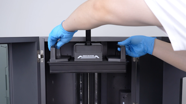
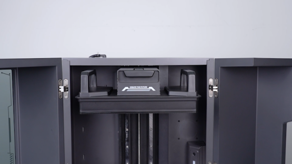
Put the build plate in the installation position. Secure the snap.
-
Get the resin tank and put it in the installation position.
-
Tighten the two knob screws.
-
Remove the bag and the cable tie.
-
Restore the automatic resin feeding inlet.
-
Close the front door.
-
Open the back cover.
-
Organize the cable and pass the cables through the base to the motherboard.
-
Put the back cover in the installation position and hold the back cover.
-
Tighten the two screws on the left side of the back cover.
-
Tighten the four screws on the front of the back cover.
-
Tighten the two screws on the right side of the back cover.
-
Plug in the cable of the automatic resin feeding inlet.
-
Plug in the cables on the motherboard according to the cable ties.
-
Put the right cover in the installation position.
-
Tighten the five screws securing the right cover.
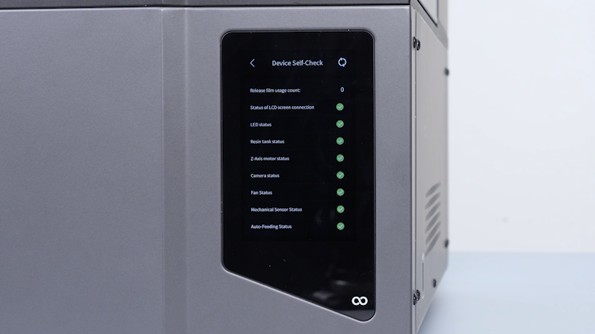
¶ Verification
-
Plug in the power supply cable and turn the power switch ON (symbol "|").
-
The printer is ready for use after the self check.