¶ Tools and Materials
-
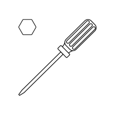
A 2.0 mm Allen key
-
A 2.5 mm Allen key
-
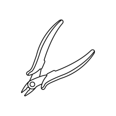
A pair of pliers
-
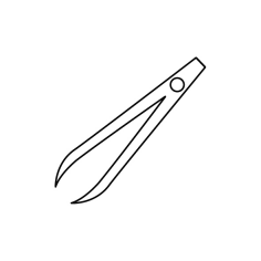
A pair of tweezers
¶ Tutorial Video
¶ Instruction
¶ Preparation
Turn the power switch OFF (symbol "〇") and unplug the power supply cable.
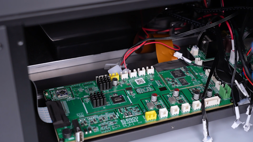
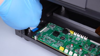
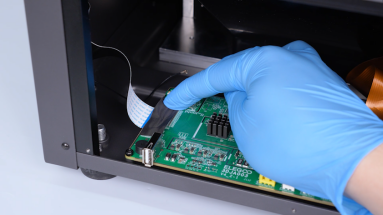
¶ Remove the old motherboard
-
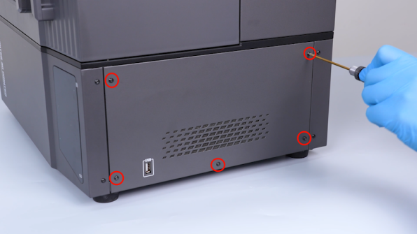
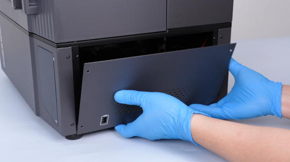
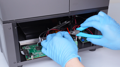
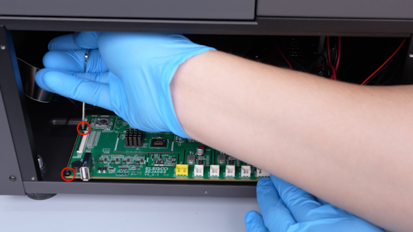
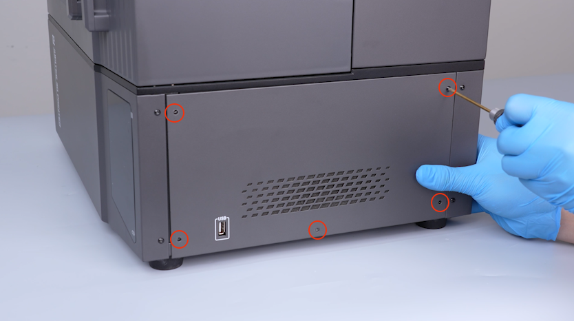
Release and remove the five screws securing the right-side cover with a 2.0 mm Allen key and remove the right-side cover.
-
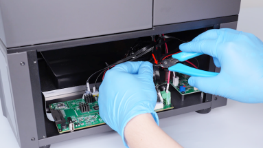
Cut off the cable ties with a pair of pliers.

-
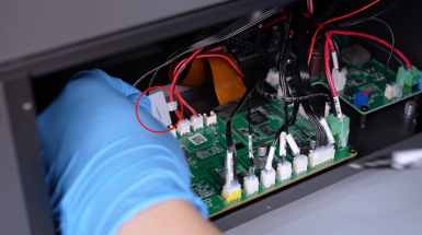
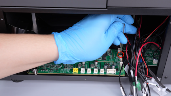
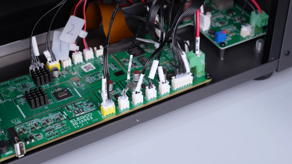
Secure the cables with cable ties and number the cable ties for cable identification.
-
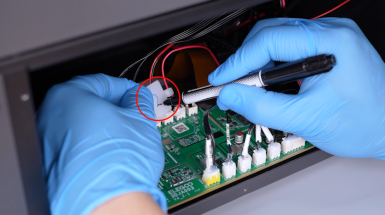
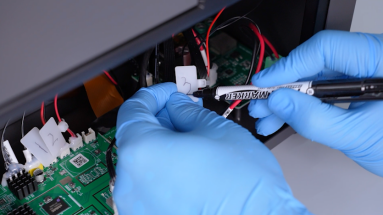
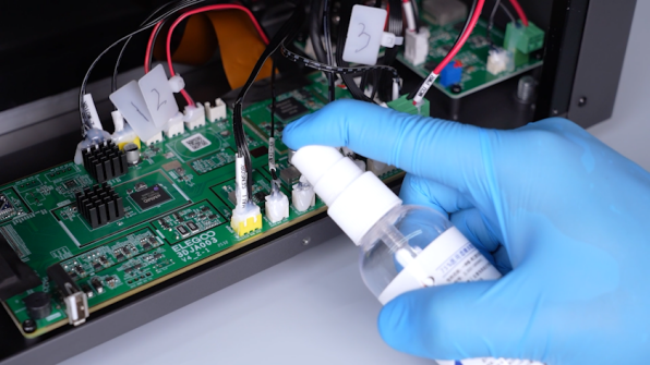
Remove the hot-melt adhesive with a pair of pliers.
Note: If the hot-melt adhesive is difficult to remove, spray a small amount of alcohol and wait for 3 - 5 minutes.
-
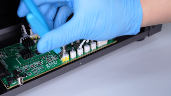
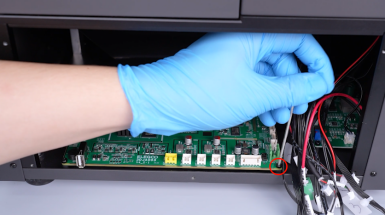
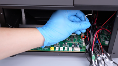
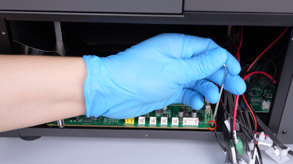
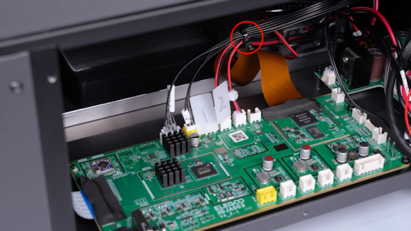
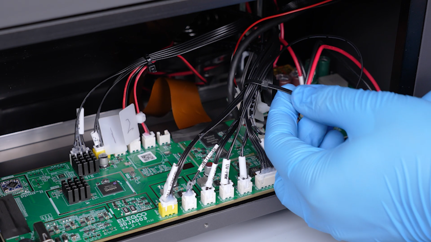
Disconnect the cables from the ports on the motherboard.
-
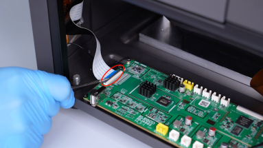
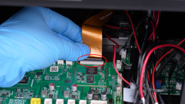
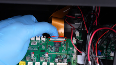
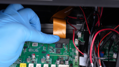
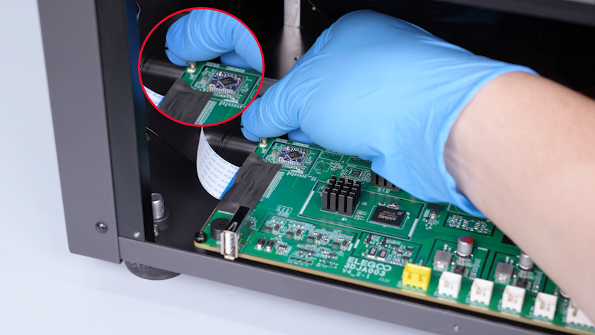
Peel off the tape securing the LCD screen ribbon cable and lift the clip. Unplug the LCD screen ribbon cable.
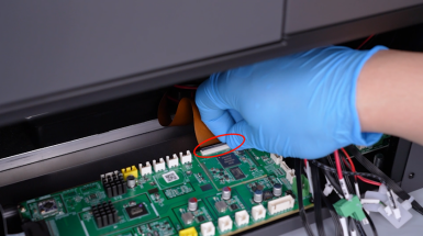
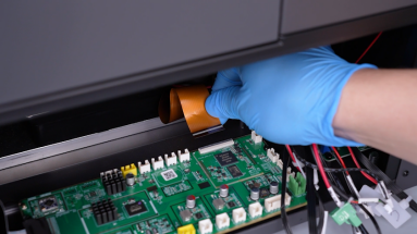
-
Peel off the tape securing the touch screen ribbon cable and lift the clip securing the touch screen ribbon cable. Unplug the touch screen ribbon cable.
-
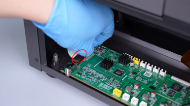
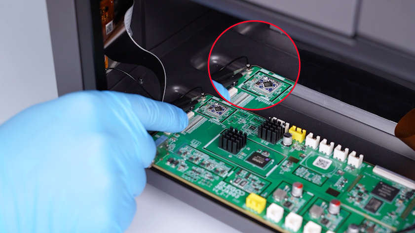
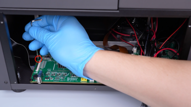
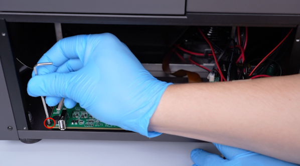
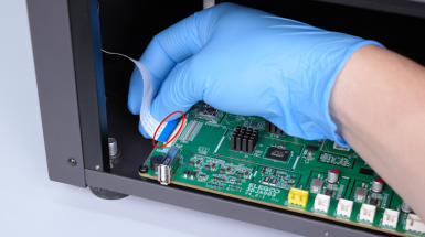
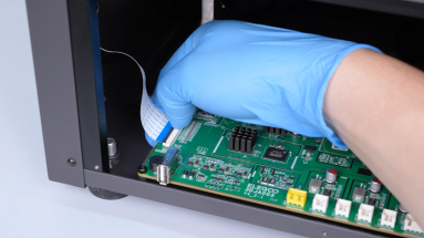
Unplug the Wi-Fi antenna with a pair of tweezers.
-
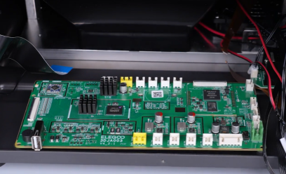
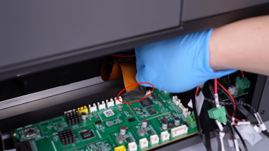
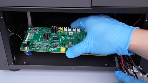
Release and remove the four screws securing the motherboard with a 2.5 mm Allen key and remove the old motherboard.
¶ Install the new motherboard
-
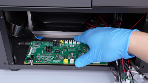
Put the new motherboard in the installation position and tighten the four screws securing the motherboard.
-
Plug in the LCD screen ribbon cable and press the clip. Secure the LCD screen ribbon cable with tape.
Note: The side of the ribbon cable with white lines must face upward.
-
Plug in the touch screen ribbon cable and press the clip. Secure the touch screen ribbon cable with tape.
Note: The blue side of the ribbon cable must face upward.
-
Plug in the Wi-Fi antenna.
-
Plug in the cables according to the labels.
-
Secure the wires with cable ties.
-
Put the right-side cover in the installation position and tighten the five screws securing the right-side cover.
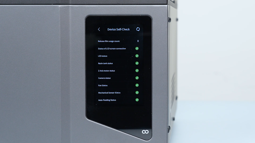
¶ Verification
-
Plug in the power supply cable and turn the power switch ON (symbol "|").
-
The printer is ready for use after the self check.