¶ Tools and Materials
-
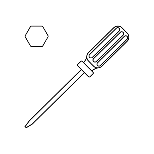
A 2.0 mm Allen key
-
A 2.5 mm Allen key
-
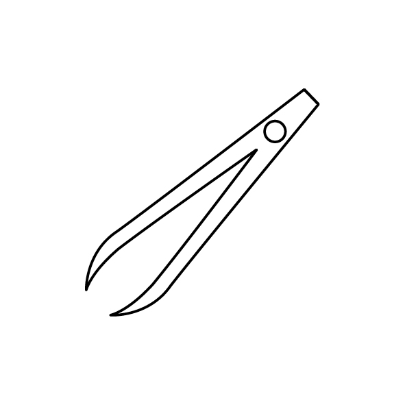
A pair of tweezers
-
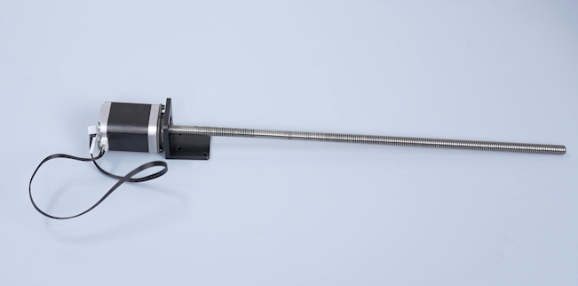
A new lead screw motor
¶ Tutorial Video
¶ Instruction
¶ Preparation
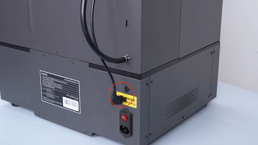
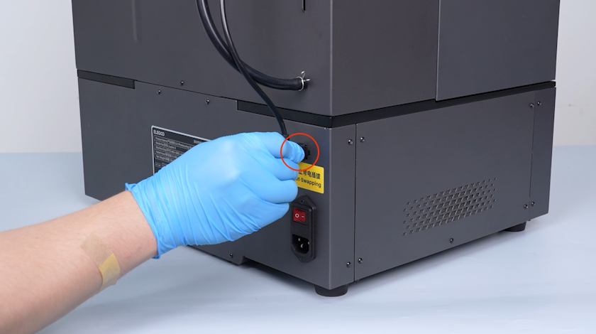
Turn the power switch OFF (symbol "〇") and unplug the power supply cable.
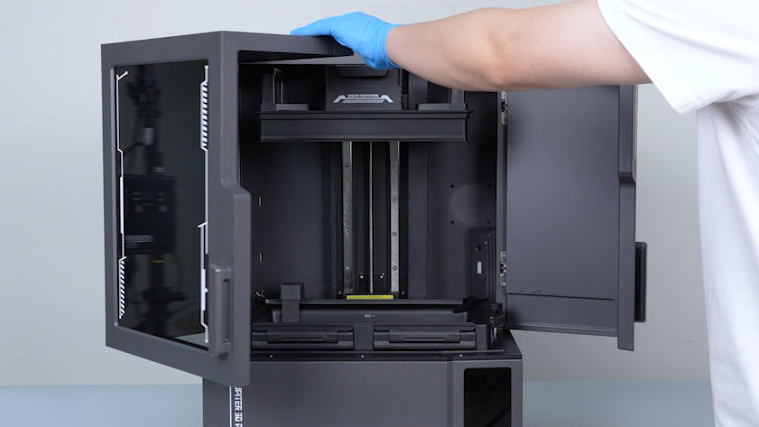
Note: Before operation, make sure that the build plate is located at the top position.
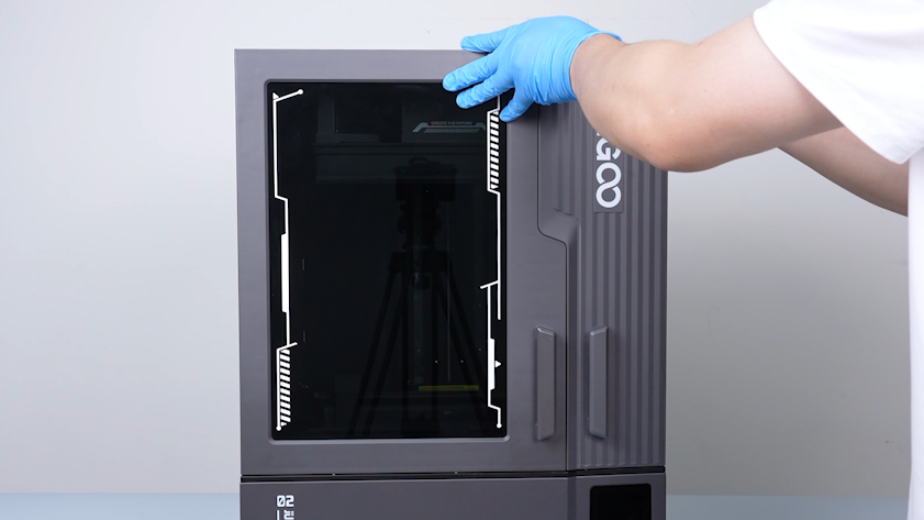
¶ Remove the right cover, build plate, resin tank
-
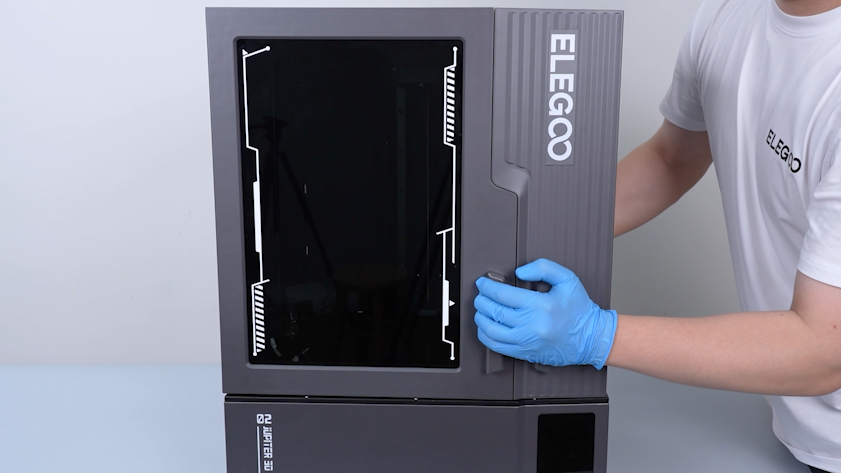
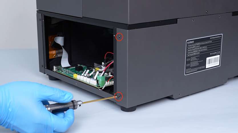
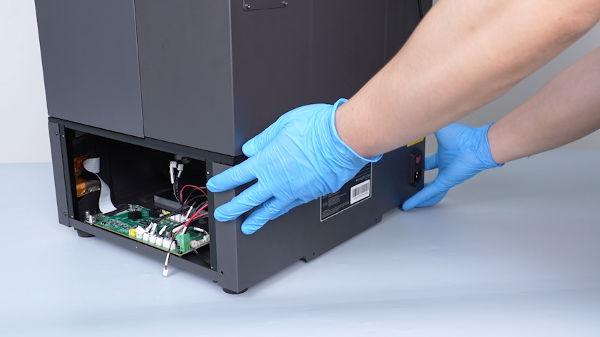
Release and remove the five screws securing the right cover with a 2.0 mm Allen key and remove the right cover.
-
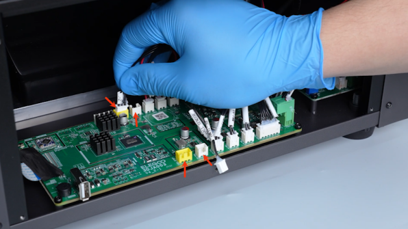
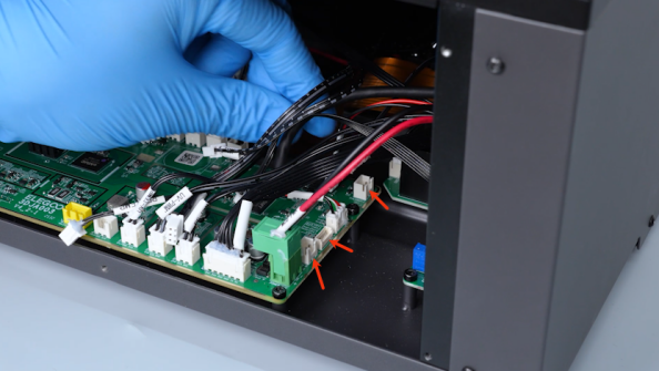
Unplug the cables.
-
Open the front door.
-
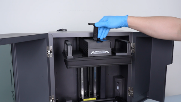
Unfasten the snap of the build plate and remove the build plate.
-
Restore the snap of the build plate.
-
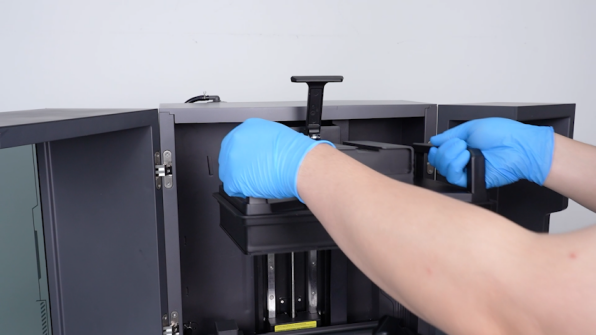
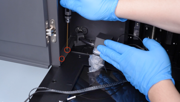
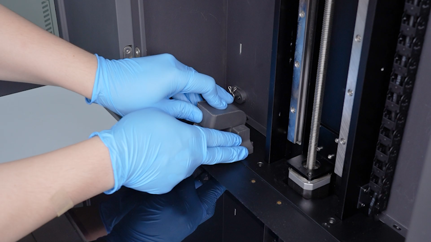
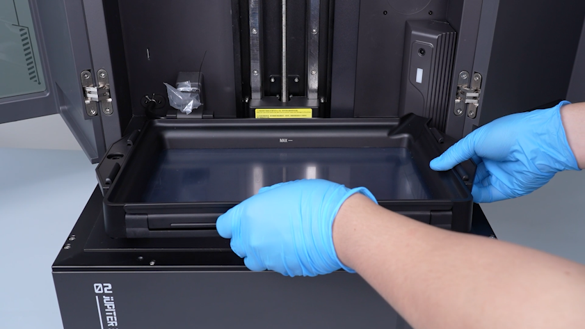
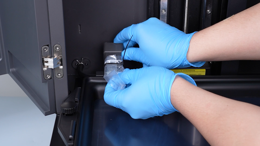
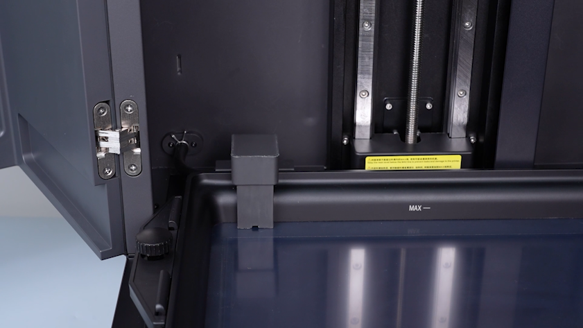
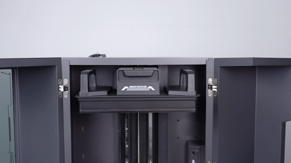
Lift the automatic resin feeding inlet.
-
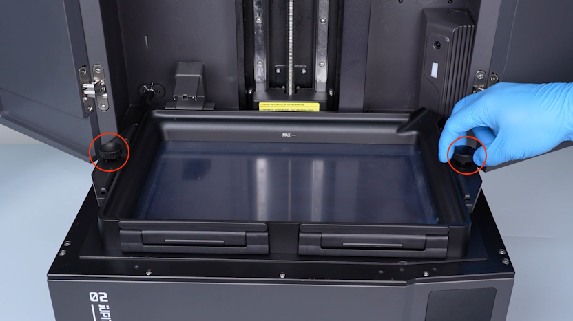
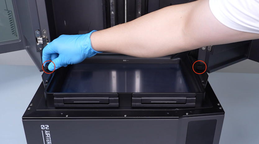
Remove the two knob screws.
-
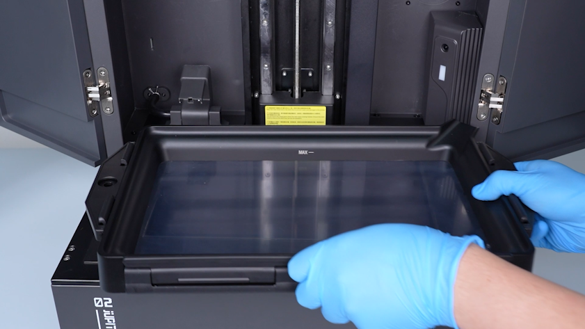
Remove the resin tank.
-
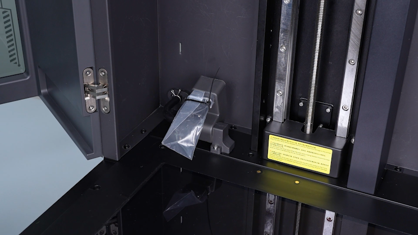
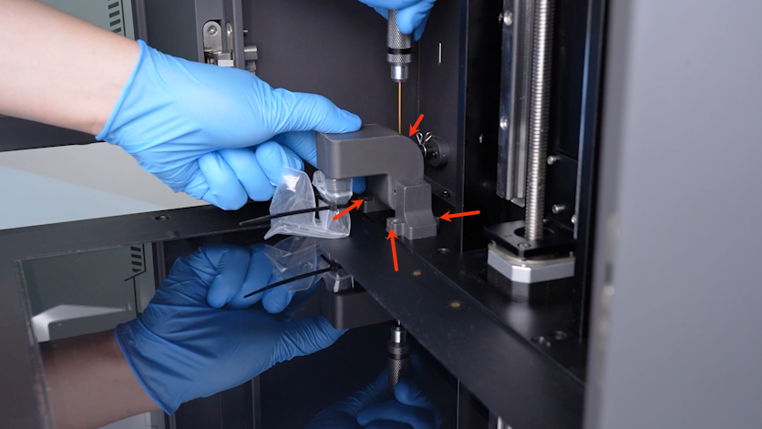
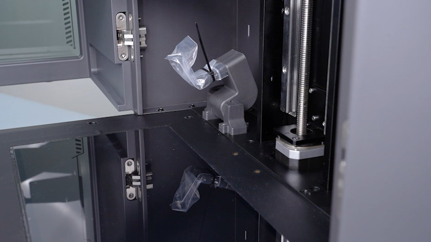
Seal the inlet with a bag and a cable tie to avoid the resin staining the LCD screen and the printer.
-
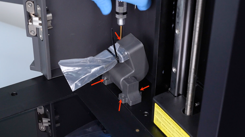
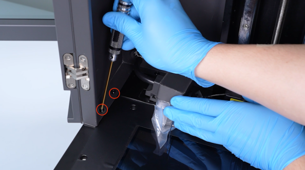
Release and remove the four screws securing the automatic resin feeding inlet with a 2.5 mm Allen key.
-
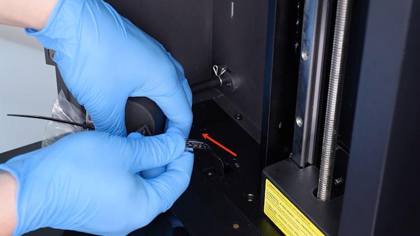
Pull the cable of the automatic resin feeding inlet out from the slot.
-
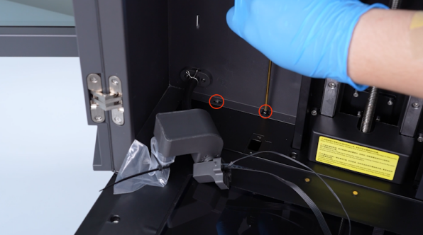
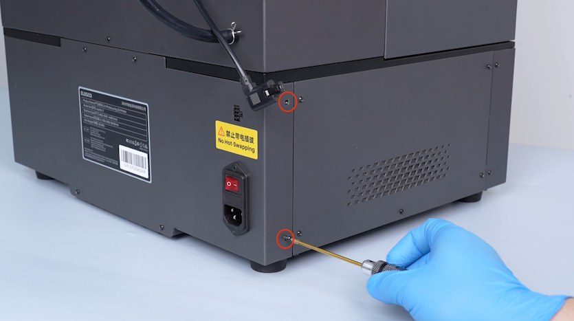
Release and remove the four screws securing the left side of the enclosure with a 2.5 mm Allen key.
-
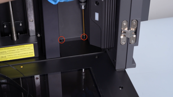
Release and remove the four screws securing the right side of the enclosure with a 2.5 mm Allen key.
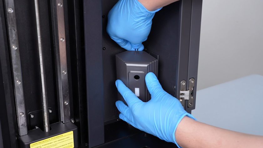
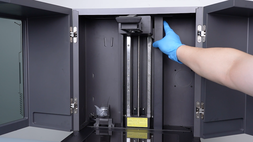
¶ Remove the Z-axis motor housing
-
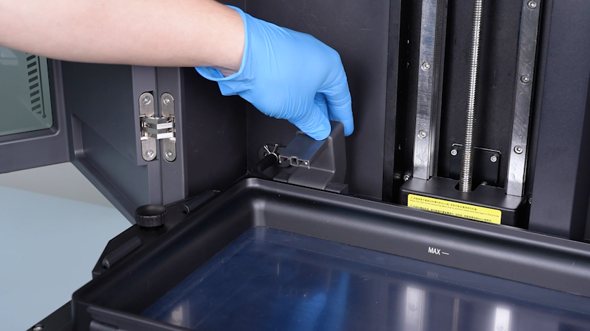
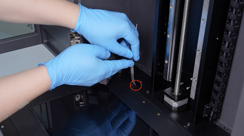
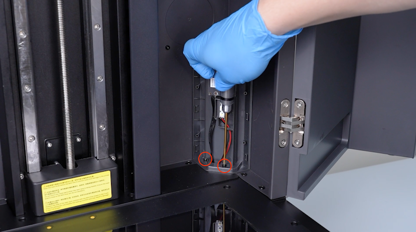
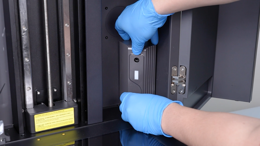
Lift the camera housing with a pair of tweezers.
-
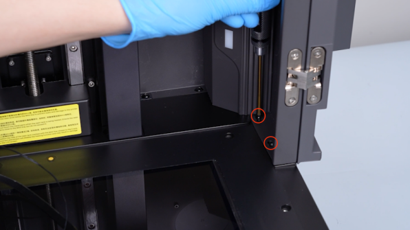
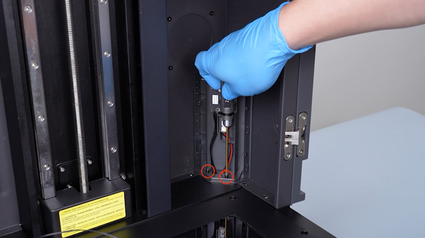
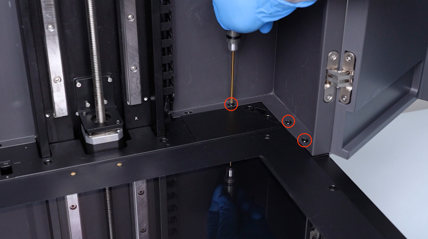
Release and remove the two screws securing the camera housing with a 2.5 mm Allen key.
-
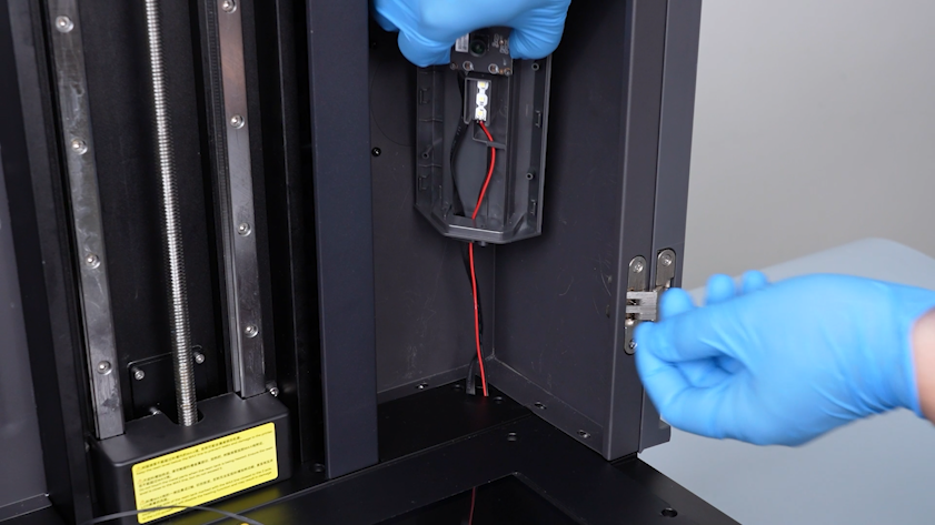
Pull the camera cable from the slot.
-
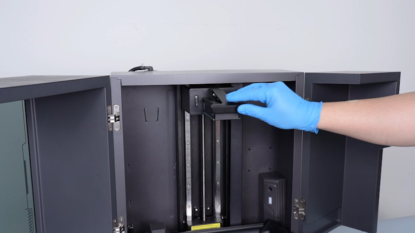
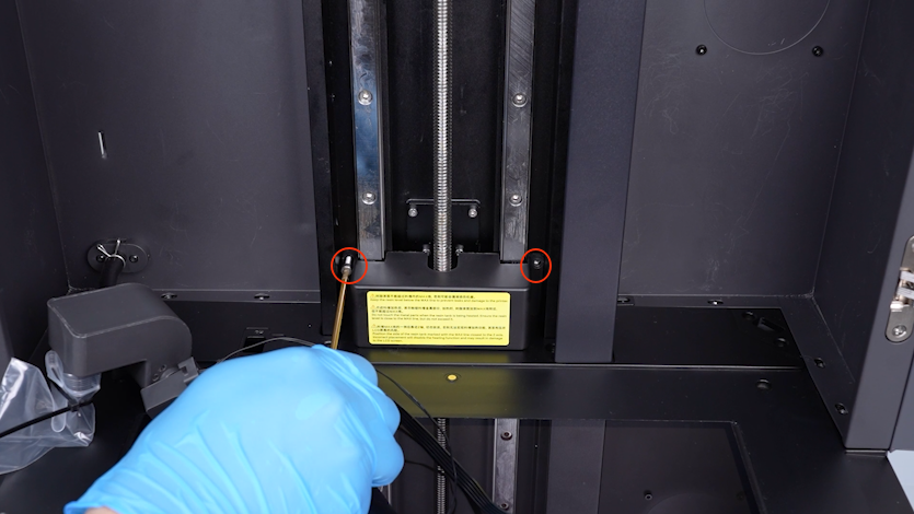
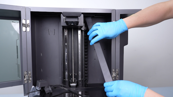
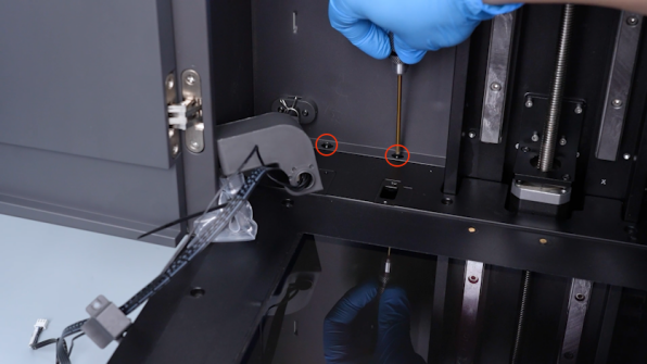
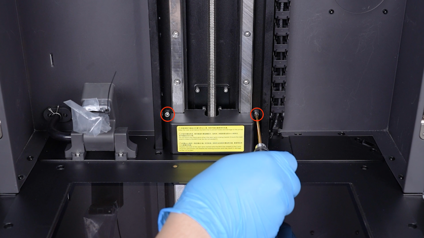
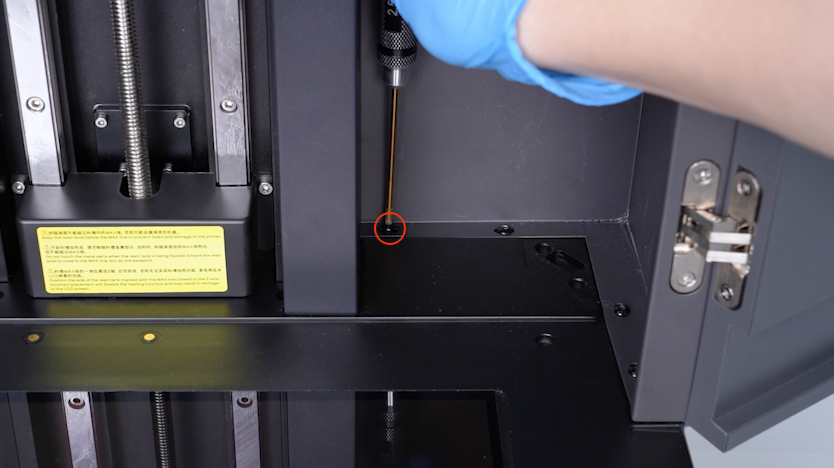
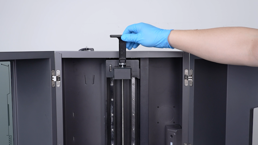
Release and remove the two screws securing the Z-axis motor housing with a 2.5 mm Allen key and remove the Z-axis motor housing.
-
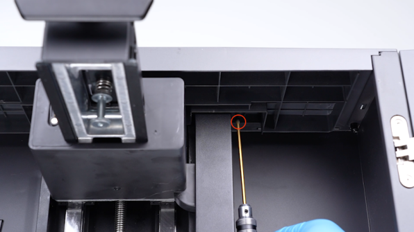
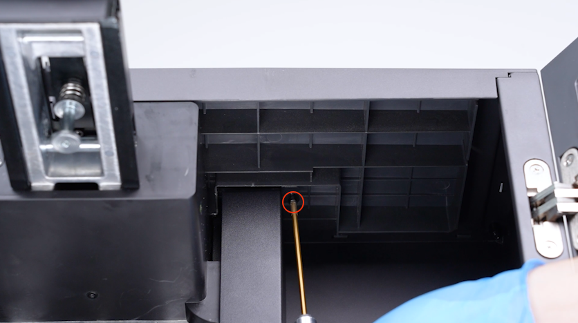
Release and remove the screw securing the top of the tank chain cable housing with a 2.5 mm Allen key and remove the tank chain housing.
-
Close the front door.
-
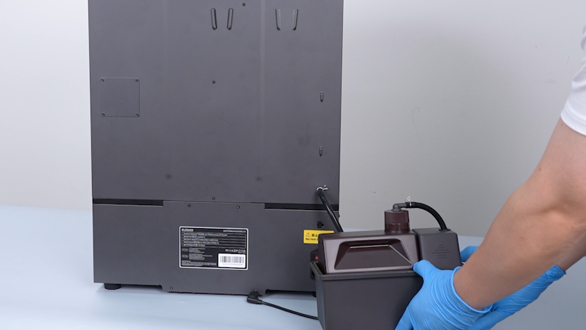
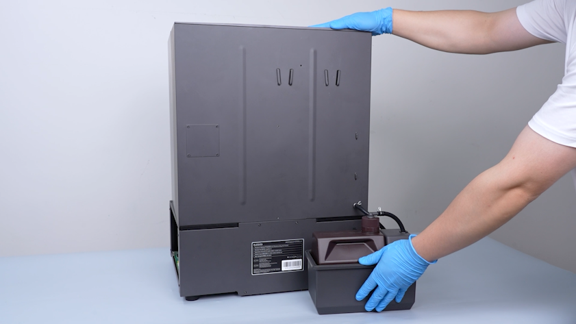
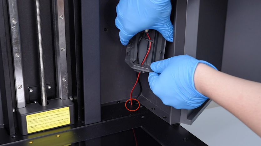
Unplug the cable of the automatic resin feeding inlet.
-
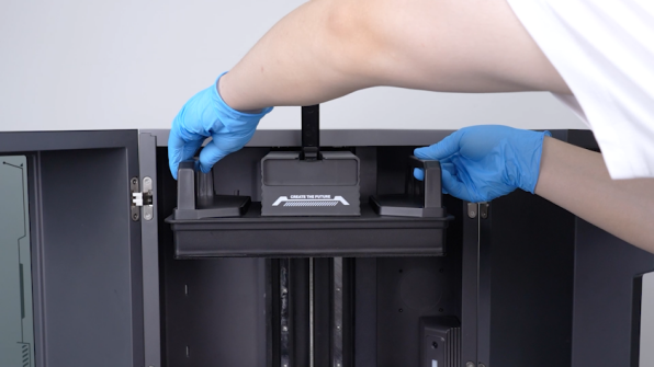
Remove the automatic resin feeding bottle and put it on the table temporarily.
-
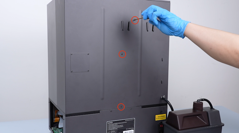
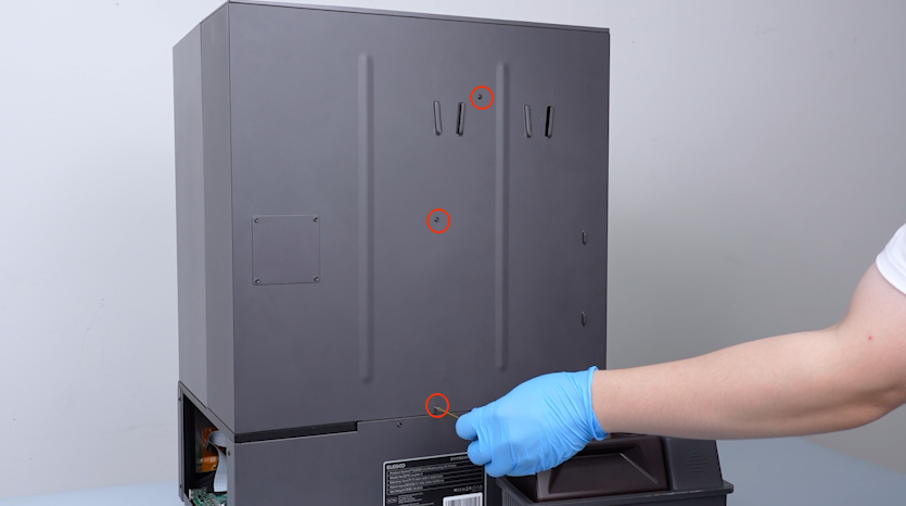
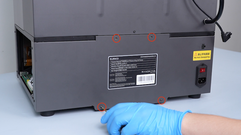
Release and remove the three screws securing the back side of the enclosure with a 2.0 mm Allen key.
-
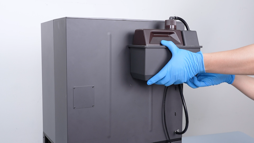
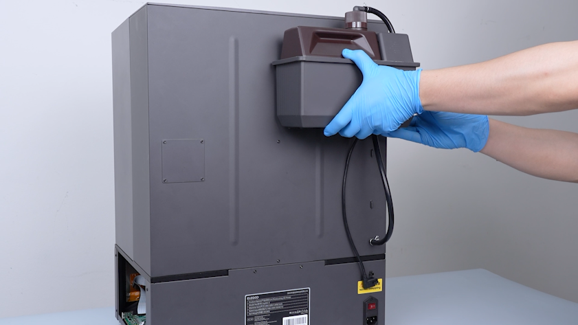
Restore the automatic resin feeding bottle.
-
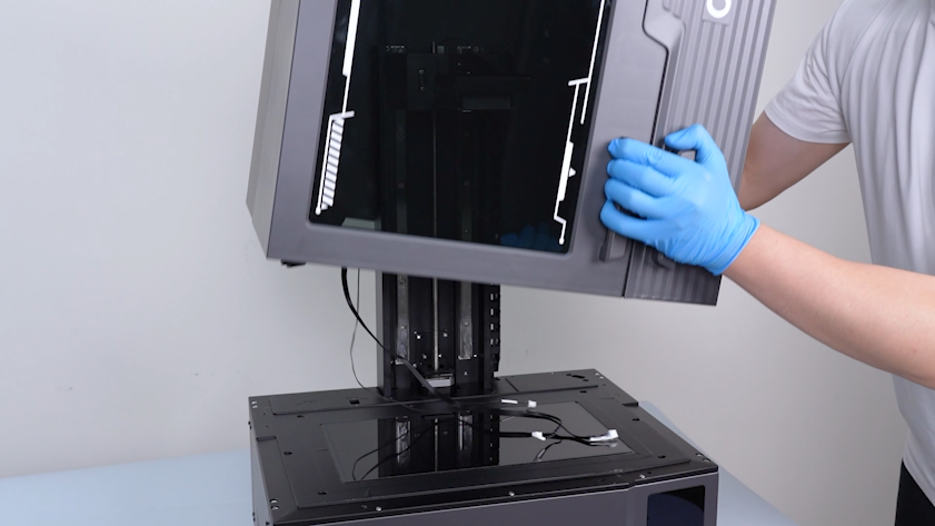
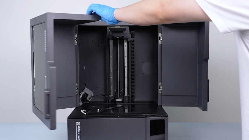
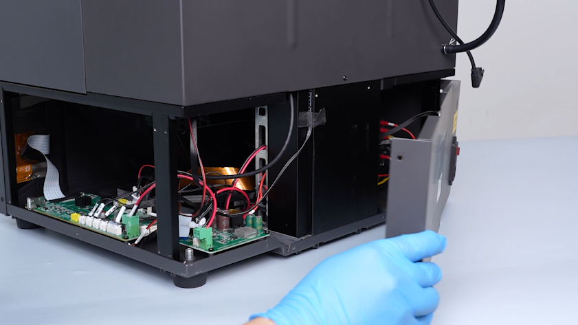
Remove the whole enclosure.
¶ Remove the old lead screw motor
-
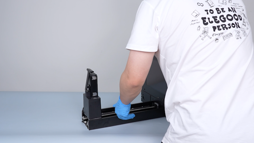
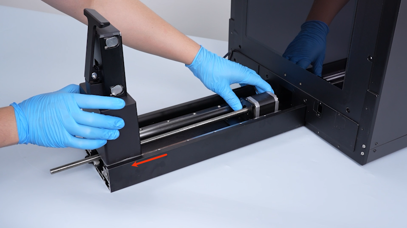
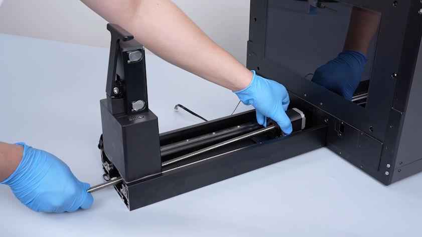
Place the printer along its Z axis.
-
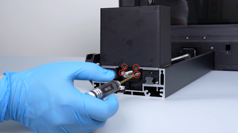
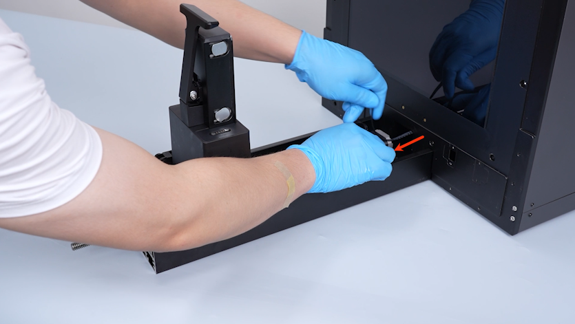
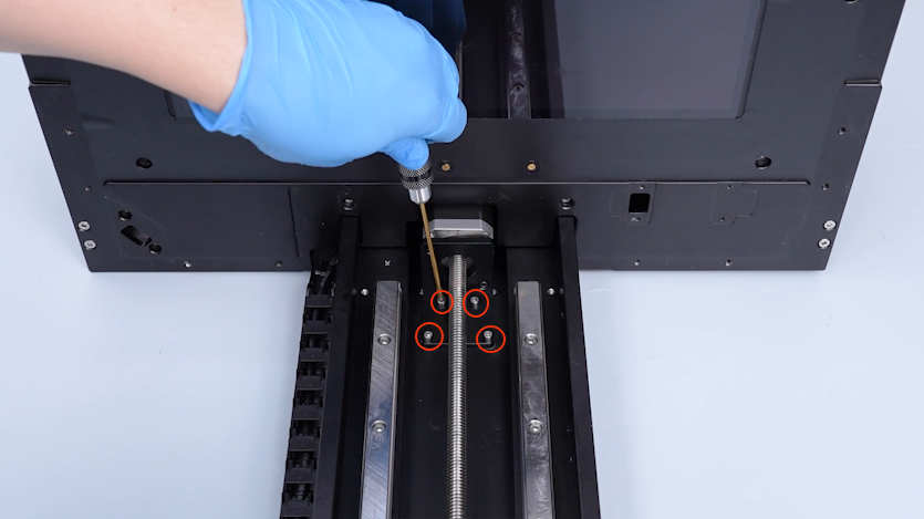
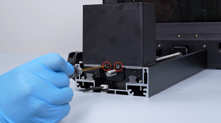
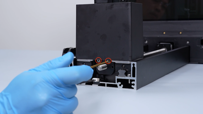
Release and remove the four screws securing the anti-backlash nut with a 2.5 mm Allen key.
Note: When removing the two screws on the upper side, loosen them first before removing.
-
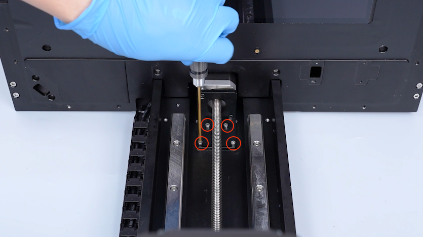
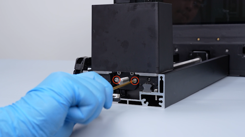
Release and remove the four screws securing the motor holder with a 2.5 mm Allen key.
-
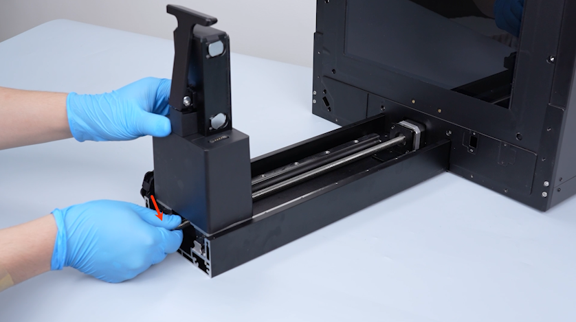
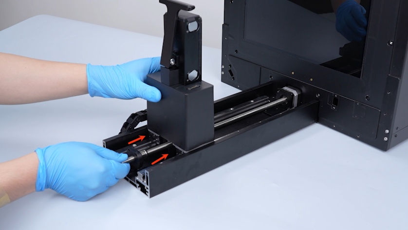
Press down the lead screw.
-
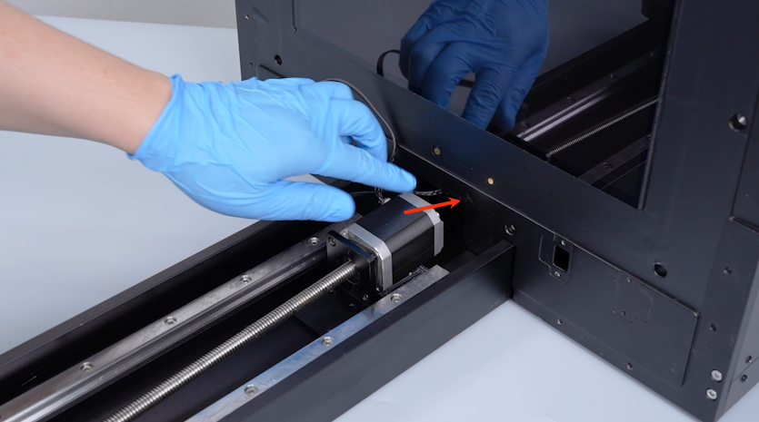
Push the cantilever by a short distance.
-
Pull the lead screw out by a short distance.
-
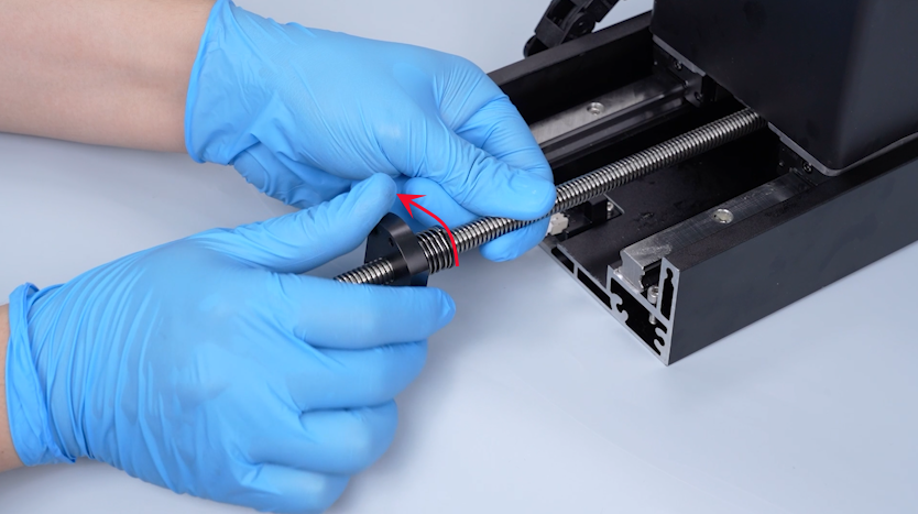
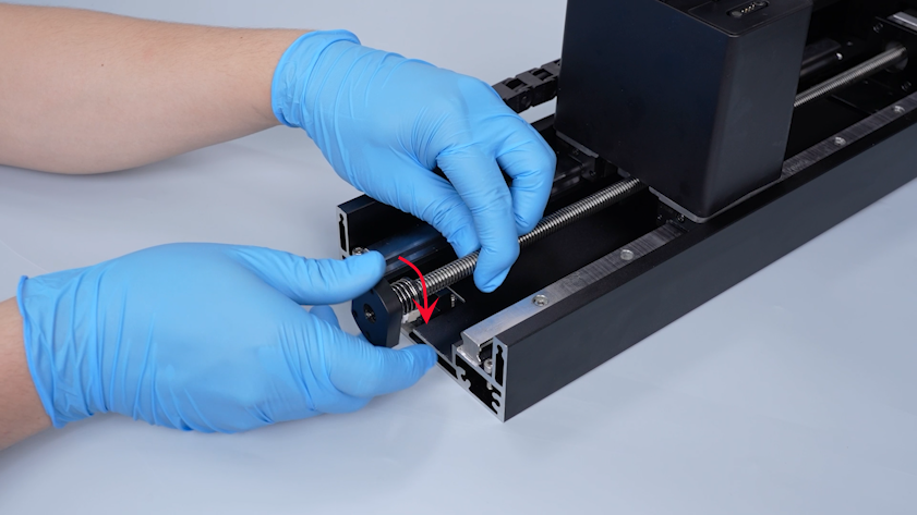
Turn the anti-backlash nut counterclockwise and remove the anti-backlash nut.
-
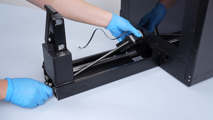
Pull the Z-axis motor cable out from the slot.
-
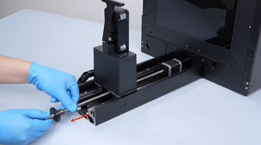
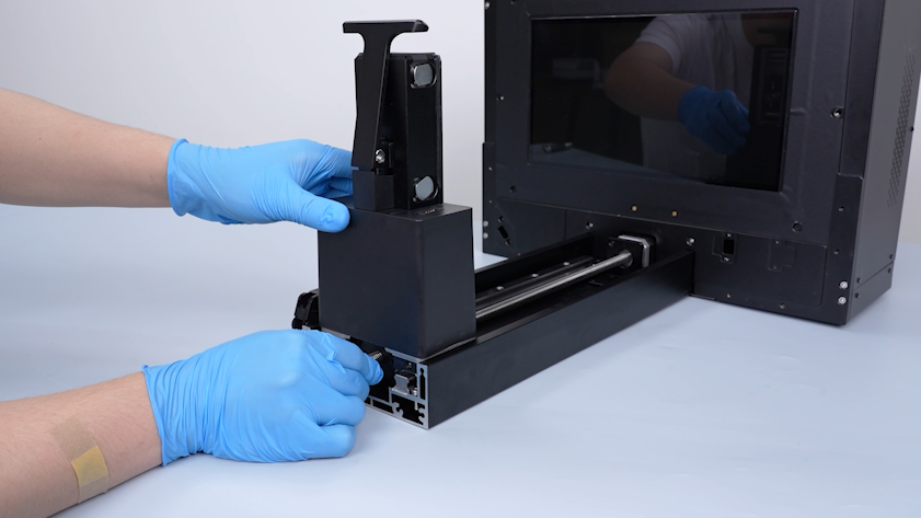
Push the cantilever to the top of the Z-axis lead screw.
-
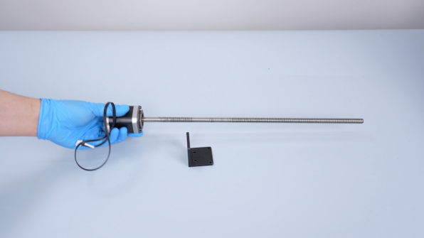
Remove the lead screw motor and the lead screw.
-
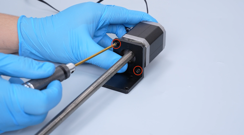
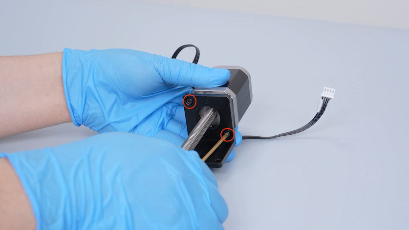
Release and remove the two screws securing the lead screw motor holder with a 2.5 mm Allen key.
-
Remove the old lead screw motor.
¶ Install the new lead screw motor
-
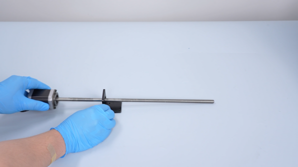
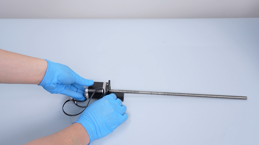
Get the new lead screw motor and the lead screw and install them through the L-shaped motor holder.
-
Tighten the two screws securing the lead screw motor holder.
-
Put the lead screw motor in the installation position.
-
Pass the lead screw motor cable through the hole.
-
Turn the anti-backlash nut clockwise and install the nut.
-
Push the cantilever to the top of the Z axis.
-
Tighten the four screws securing the lead screw motor holder.
-
Install the two screws on the upper part of the anti-backlash nut.
Note: Do not tighten the screws at this time.
-
Tighten the two screws on the upper part of the anti-backlash nut.
-
Tighten the two screws on the lower part of the anti-backlash nut.
¶ Install the Z-axis motor housing
-
Put the enclosure in the installation position.
-
Remove the automatic resin feeding bottle and put it on the table temporarily.
-
Tighten the three screws securing the enclosure.
-
Restore the automatic resin feeding bottle.
-
Open the front door.
-
Tighten the four screws securing the left side of the enclosure with a 2.5 mm Allen key.
-
Tighten the three screws securing the right side of the enclosure with a 2.5 mm Allen key.
-
Pass the cable of the automatic resin feeding inlet through the slot.
-
Restore the automatic resin feeding inlet.
-
Tighten the four screws securing the automatic resin feeding inlet.
-
Lift the automatic resin feeding inlet.
-
Put the housing of the lead screw motor in the installation position and tighten the two screws securing housing of the lead screw motor.
-
Put the housing of the tank chain in the installation position.
-
Tighten the screw securing the lower part of the housing of the tank chain.
-
Tighten the screws securing the upper part of the housing of the tank chain.
¶ Install the right cover, build plate and resin tank
-
Pass the camera cable through the slot.
-
Tighten the two screws securing the camera with a 2.5 mm Allen key.
-
Put the camera housing in the installation position.
-
Put resin tank in the installation position.
-
Tighten the two knob screws.
-
Remove the bag and the cable tie.
-
Restore the automatic resin feeding inlet.
-
Unfasten the snap of the build plate.
-
Put the build plate in the installation position.
-
Close the front door.
-
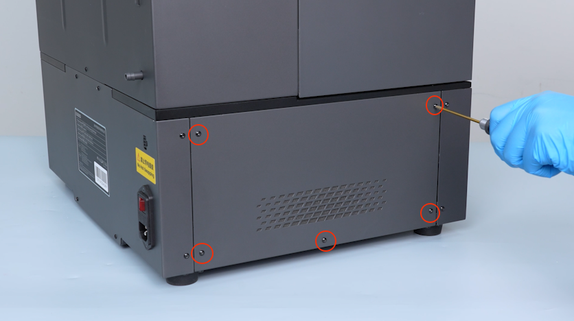
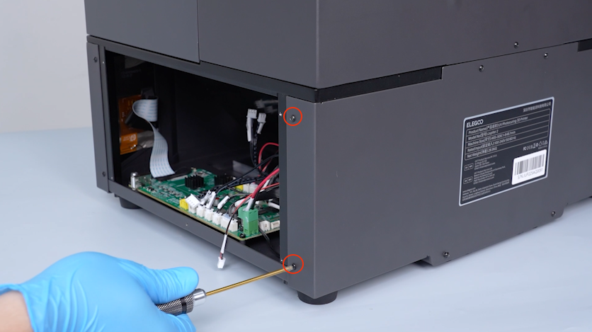
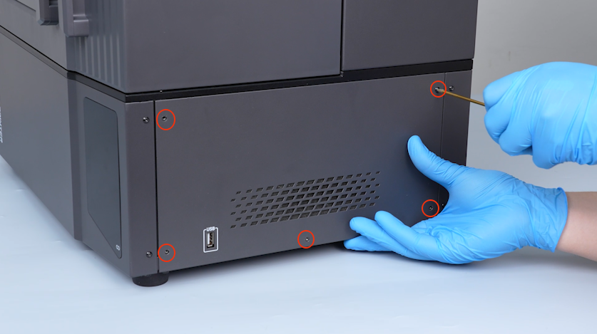
Remove the two screws on the right side of the back cover.
-
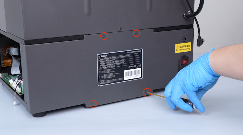
Remove the four screws on the front of the back cover.
-
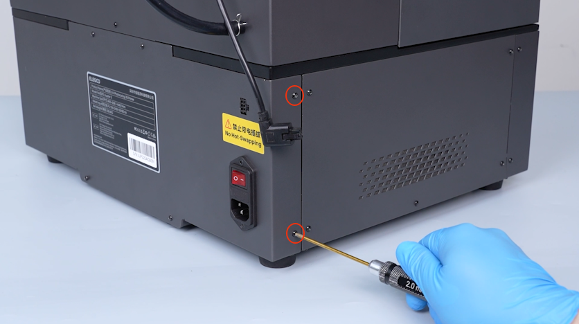
Remove the two screws on the left side of the back cover.
Note: Hold the back cover when releasing the last screw.
-
Open the back cover.
-
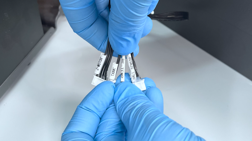
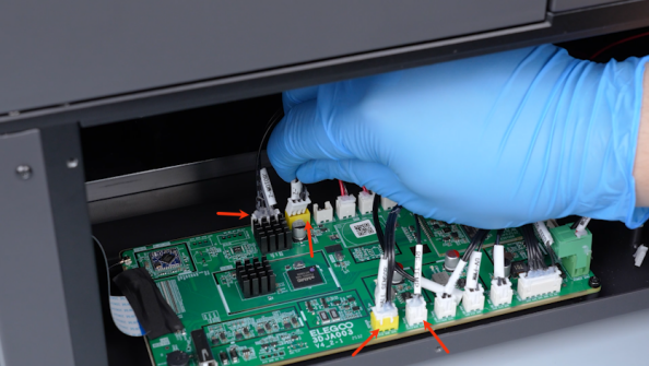
Organize the cables.
Note: The cables are Z-MOTOR cable, TANK cable, RF-TEMP cable and HALL SENSOR cable.
-
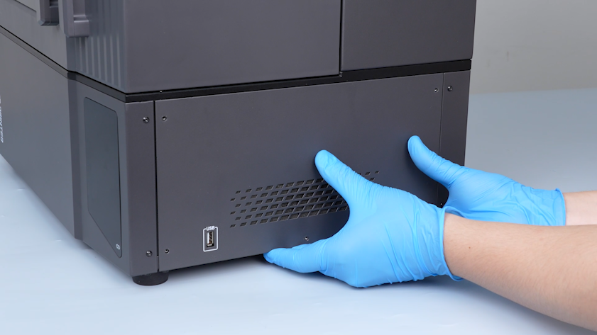
Pass the cables through inside of the base.
-
Put the back cover in the installation position.
-
Tighten the four screws on the front of the back cover.
-
Tighten the two screws on the left side of the back cover.
-
Tighten the two screws on the right side of the back cover.
-
Plug in the cable of the automatic resin feeding inlet.
-
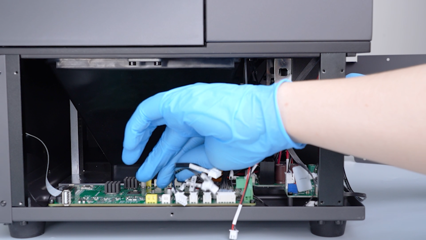
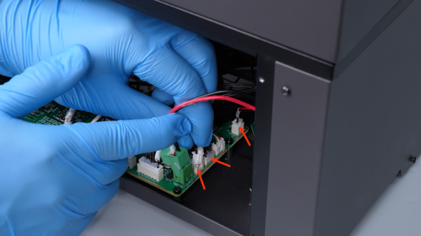
Plug in the cables according to the labels.
-
Put the right cover in the installation position.
-
Tighten the five screws securing the right cover.
¶ Verification
-
Plug in the power supply cable and turn the power switch ON (symbol "|").
-
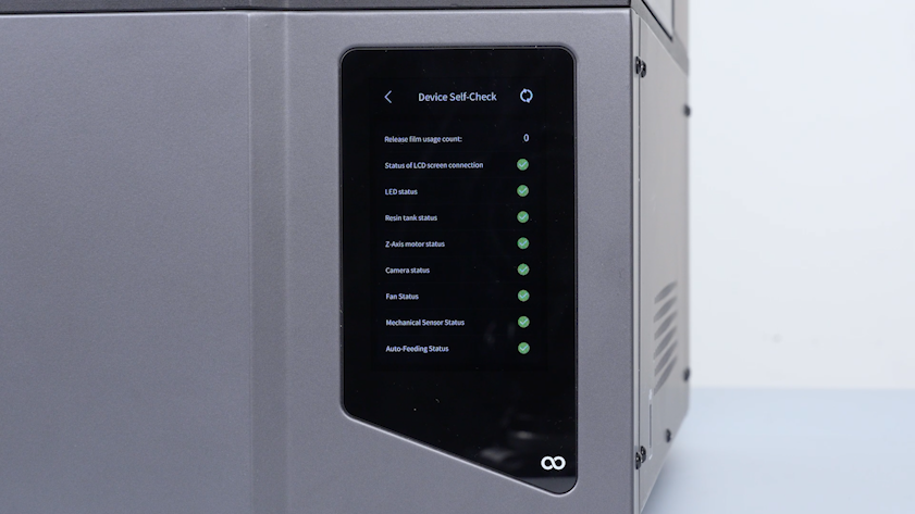
Wait for the printer to complete the self-check process.
-
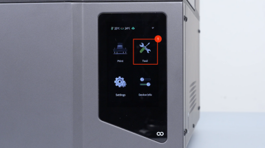
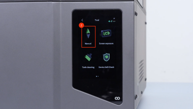
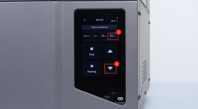
On the touch screen, select Tools - Manual - 50 mm - ▽.
-
The printer is ready for use after the self check.