¶ Issue description
The UV light cannot illuminate during the startup of the printing process or when conducting LCD screen exposure tests. It prevents the resin from curing properly.
¶ Why it happens
- The adapter is not compatible with the printer.
- The long-term use of the equipment leads to increase in power consumption, triggering the original adapter protection due to insufficient power.
- The connection of the wires has failures.
- There are problems with the motherboard, adapter or the step up converter board.
¶ Solutions
¶ Check the compatibility of the adapter with the printer.
- Check the output voltage (V), rated current (A), and rated power (W, which is voltage × current) on the power adapter label. C
- Compare them one by one with the power input specifications indicated on the printer's nameplate.
If the specifications do not match, for example, the voltage being too high/too low or insufficient current, replace the adapter with one that meets the nameplate parameters for testing, preventing the motherboard or light board from damaging due to specification incompatibility.
¶ Check the power compatibility with the adapter.
After long-term use of the printer, components such as wiring, power boosters, and adapter boards may experience increased resistance due to aging, leading to higher actual power consumption.
- Replace the original adapter with another adapter of the same voltage but higher rated current (not exceeding the maximum allowable value of the printer) for testing. For example, the original 12V 3A adapter can be replaced with a 12V 5A one.
- After replacement, if the UV light is on, it indicates that the original adapter is underloaded and needs to be replaced with a higher power adapter.
¶ Check the reliability of the wires’ connection.
¶ Step 1. Check the main wires.
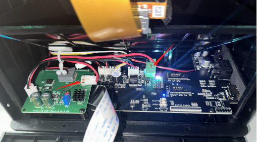
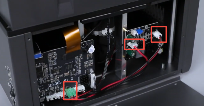
Check the power supply lines and signal lines between the motherboard and the lamp board, including the signal line that controls the UV lamp switch, as well as the connectors at both ends of the lines, including the motherboard interface and the lamp board interface.
¶ Step 2. Comprehensive visual inspection.
- Check the cable for any damage or cracks, especially at points where it bends frequently, such as segments near the connector.
- Ensure the insulation layer has not come off exposing the copper wire.
- Inspect the metal contacts of the plug for any signs of oxidation or deformation, and check if the interface is loose or misaligned, for example, if the plug's locking clip is broken and cannot secure tightly.
¶ Step 3. Cleaning and fastening treatment.
- For the oxidized plug contacts, repeatedly wipe them with a cotton swab dipped in a small amount of alcohol until they shine with a metallic luster.
- Connect after the alcohol has completely evaporated to avoid short circuit.
- Align the plug with the port and insert it vertically. If the plug is snap design, there will be a "click" sound.
- Gently pull the cable to check for looseness, ensuring there are no poor connections.
¶ Measure voltages with a multimeter.
¶ Step 1. Check the voltage output from the motherboard to the step up converter board.
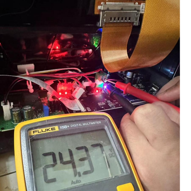
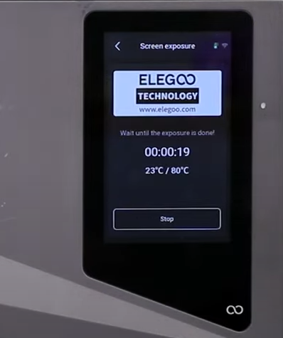
- Turn on the printer and activate the UV lamp, for example, to perform the exposure testing.
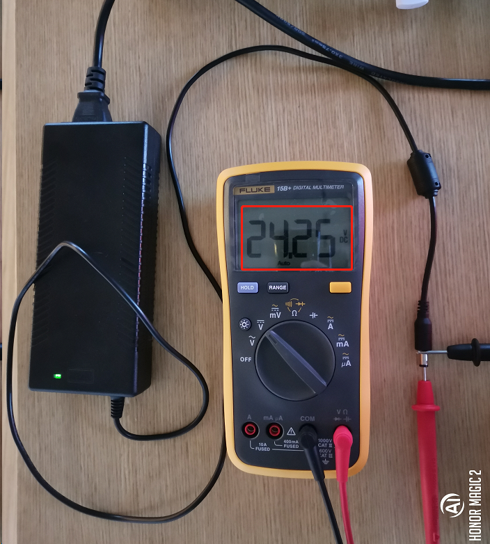
- Set the multimeter to the DC voltage range (DCV).
- Connect the red probe to the positive terminal of the motherboard output, and the black probe to the negative terminal.
Note: Refer to the power supply interface of the step up converter board indicated in the equipment circuit diagram. - Check the nominal output voltage of the motherboard.
The value of the motherboard must be 12V or 24V.
If the motherboard outputs an abnormal voltage, either 0 or lower, the issue lies with the motherboard or the adapter. Replace the adapter for testing.
¶ Step 2. Check the input/output voltage of the booster board.
- Measure the input voltage of the boost converter which should match the output voltage of the motherboard.
- Measure the output voltage of the boost converter which should correspond to the rated working voltage of the lamp board, such as 24V or 12V.
If the step up converter board input is normal but the output is abnormal, it is a fault of the step up converter board, then a new step up converter board needs to be replaced. If the step up converter board output is normal but still cannot light up the UV lamp, the lamp board is damaged, then a new lamp board needs to be replaced.