¶ Required Tools
2.5 mm Allen Key
1.5 mm Allen Key
Phillips Screwdriver
New PTC Assembly and Temperature Control Switch Fixing Part
¶ Disassembly Steps
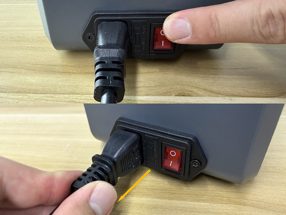
Reminder: Before starting the operation, turn off the H1 HT power switch and unplug the power cord. Make sure the device is completely powered off before proceeding.
¶ Remove The Filament
- Open the top cover.
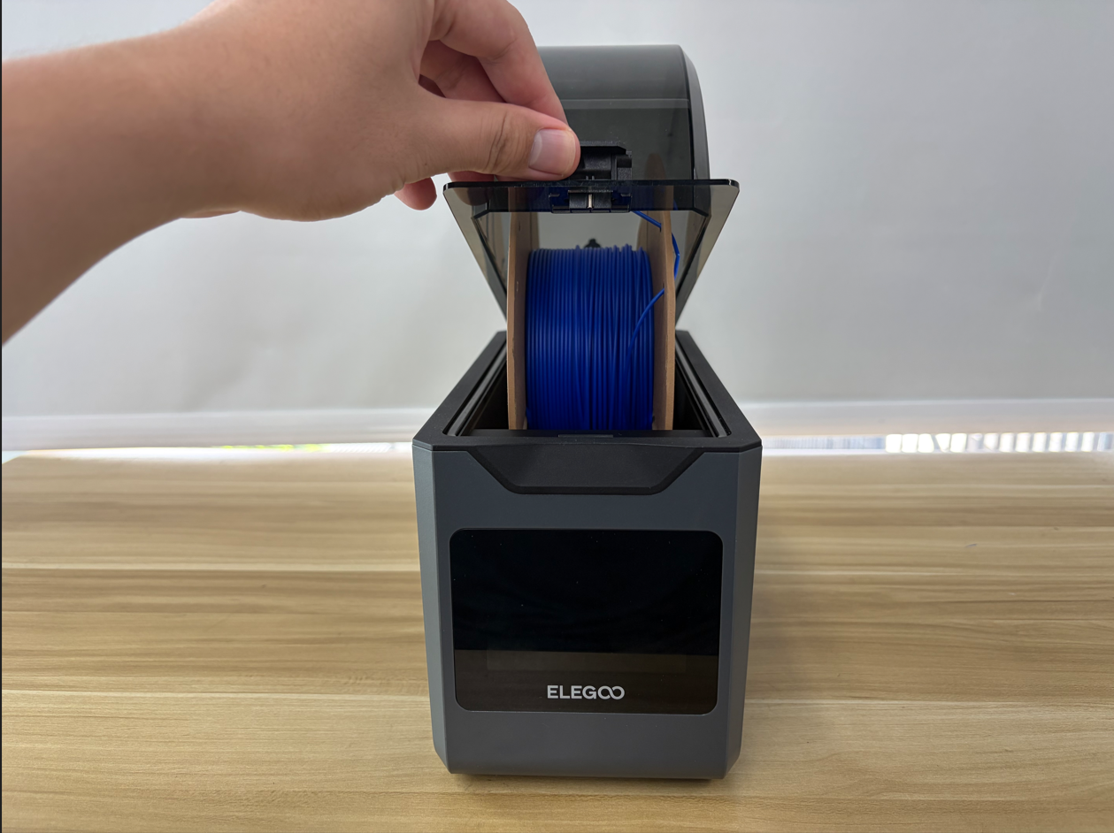
- Remove the filament.
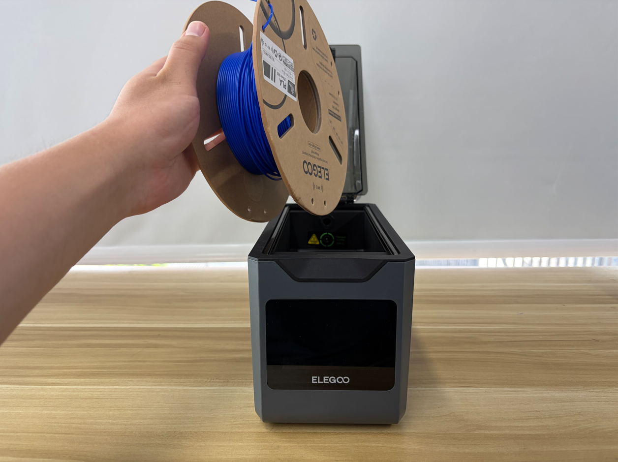
- Close the top cover.


¶ Open The Bottom Cover
- Place the H1 HT on its side on a level surface.
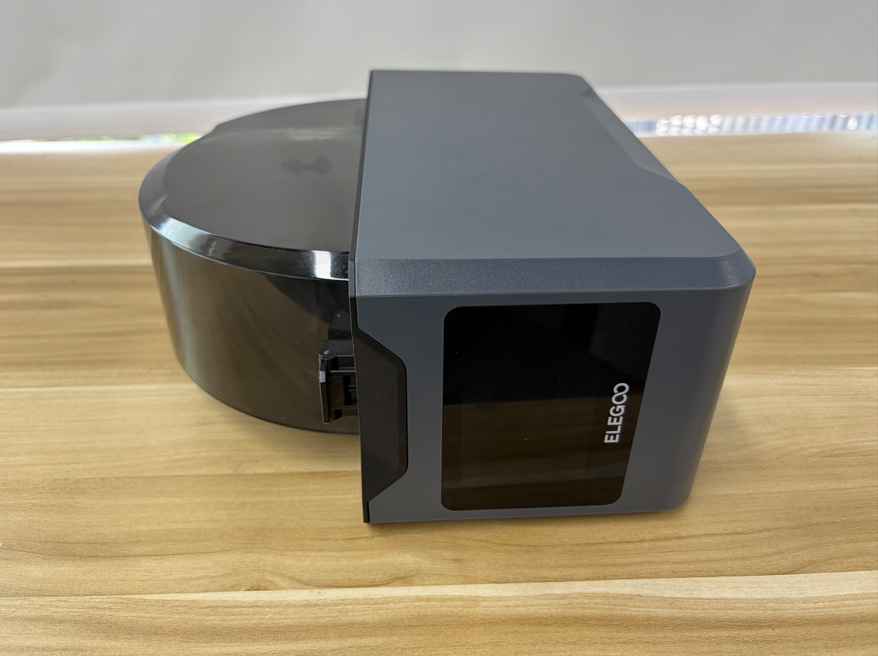
- Use a 2.5 mm Allen Key to remove the four screws securing the bottom cover.
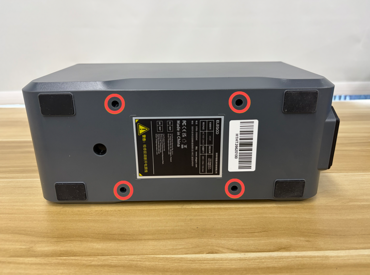
- Slowly open the bottom cover. Be careful not to pull or damage the internal cables.
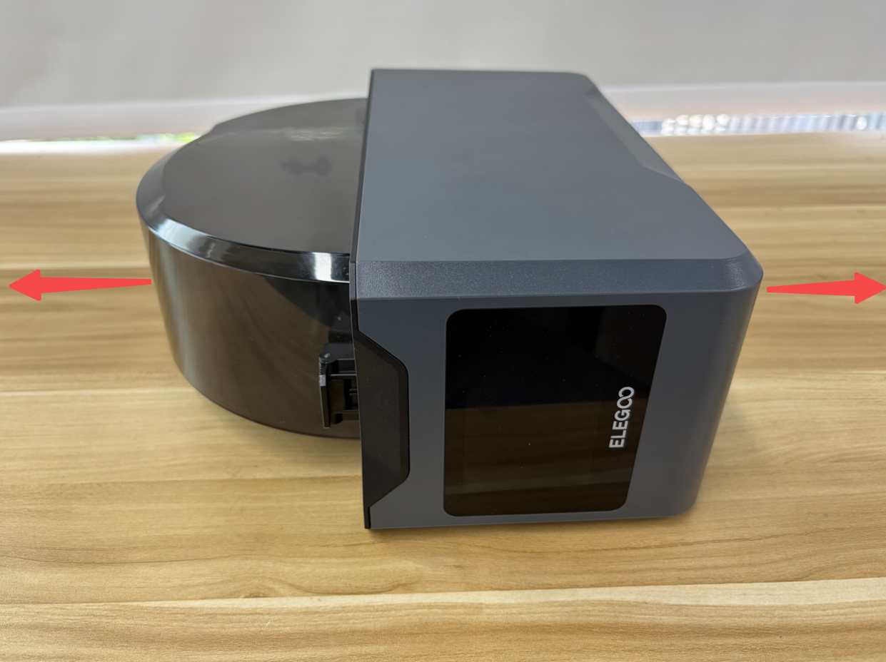
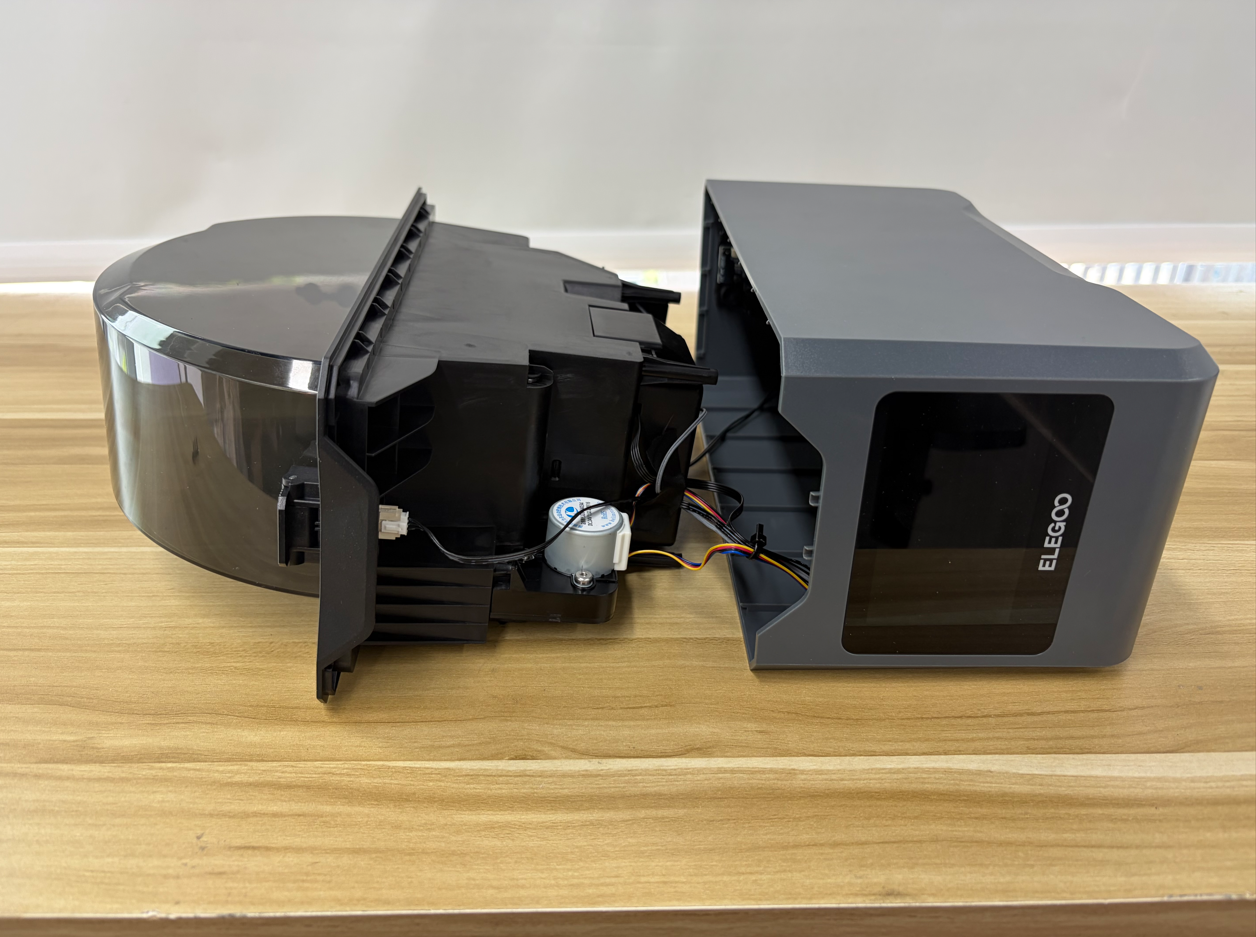
- Place the bottom of the machine facing downward on a level surface.
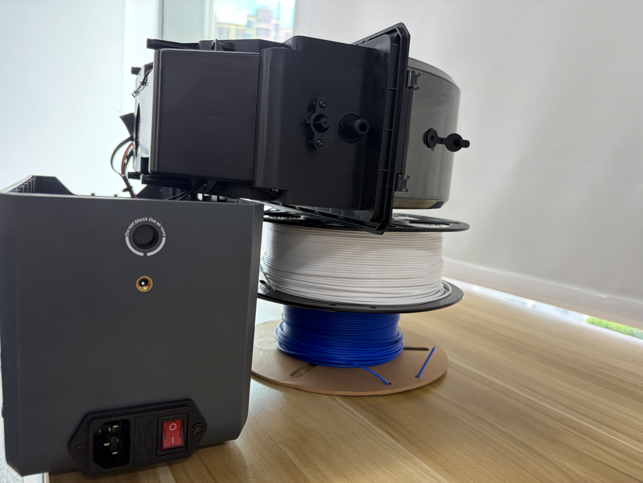
Reminder: To facilitate subsequent operations, two filament spools can be placed under the inner tray assembly and top cover as supports.
¶ Disconnect The PTC Assembly Cables From The Power Supply Board
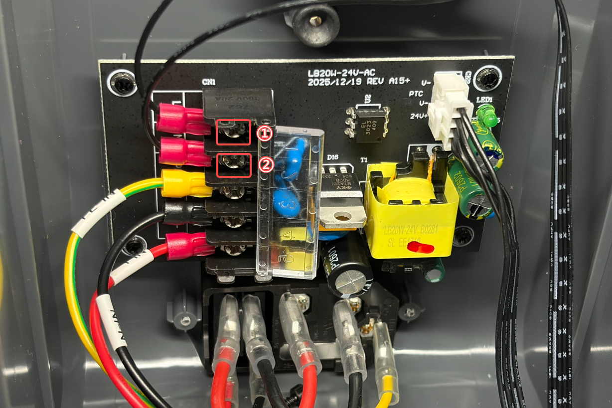
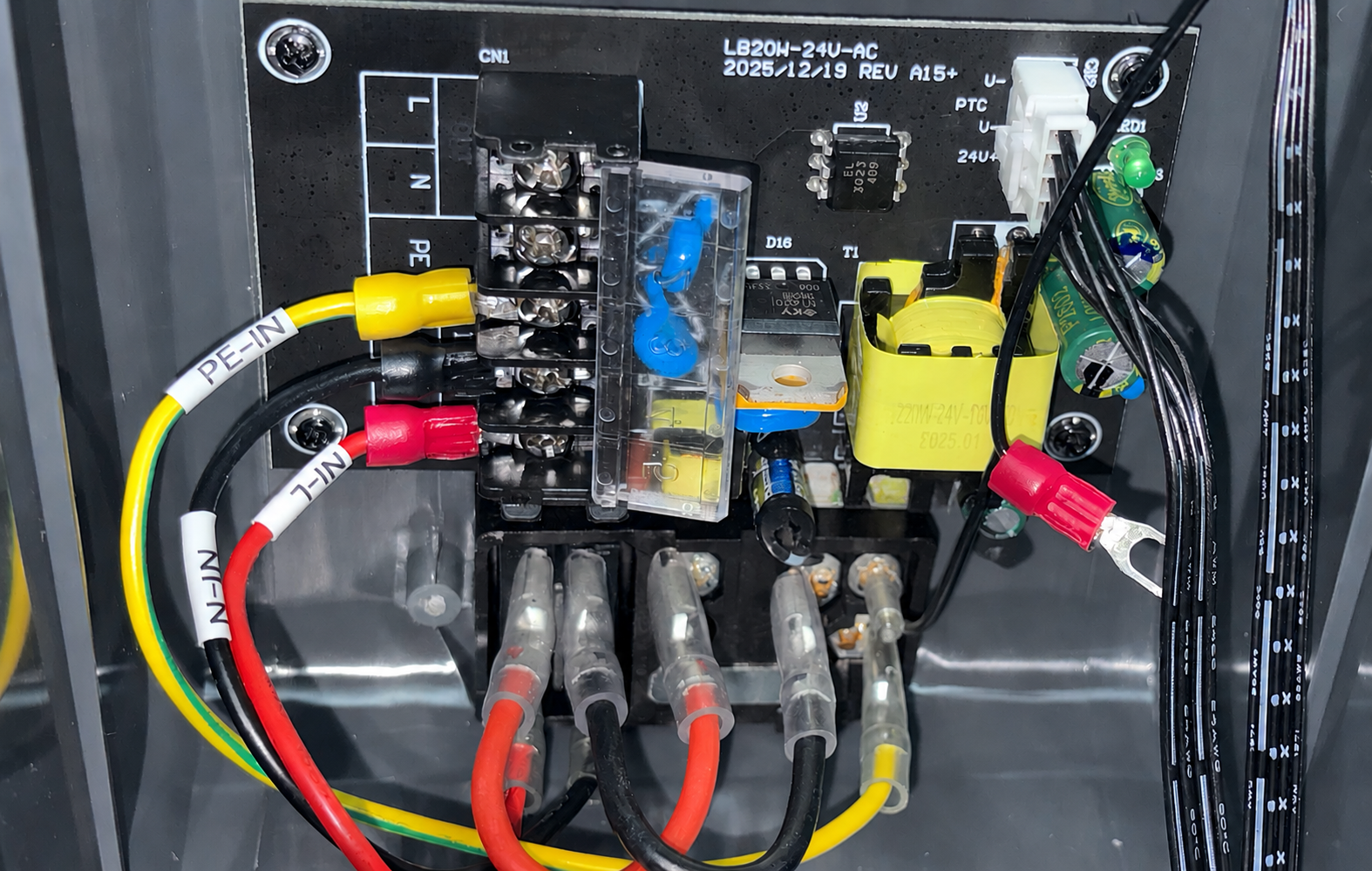
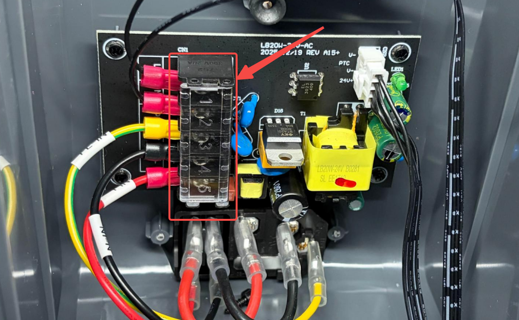
- Open the power cord protection cover. Use a Phillips Screwdriver to loosen the screws securing cables ① and ②, then remove the two cables in sequence.
¶ Remove The Air Duct Protection Assembly
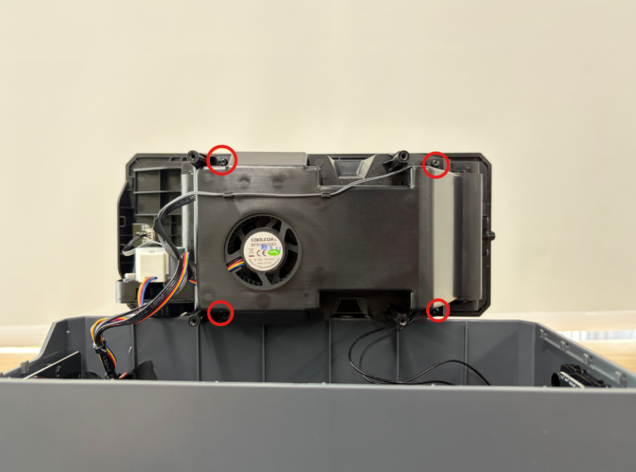
- Use a 1.5 mm Allen Key to remove the four screws securing the air duct protection assembly.
- Slowly separate the inner tray assembly from the bottom cover.
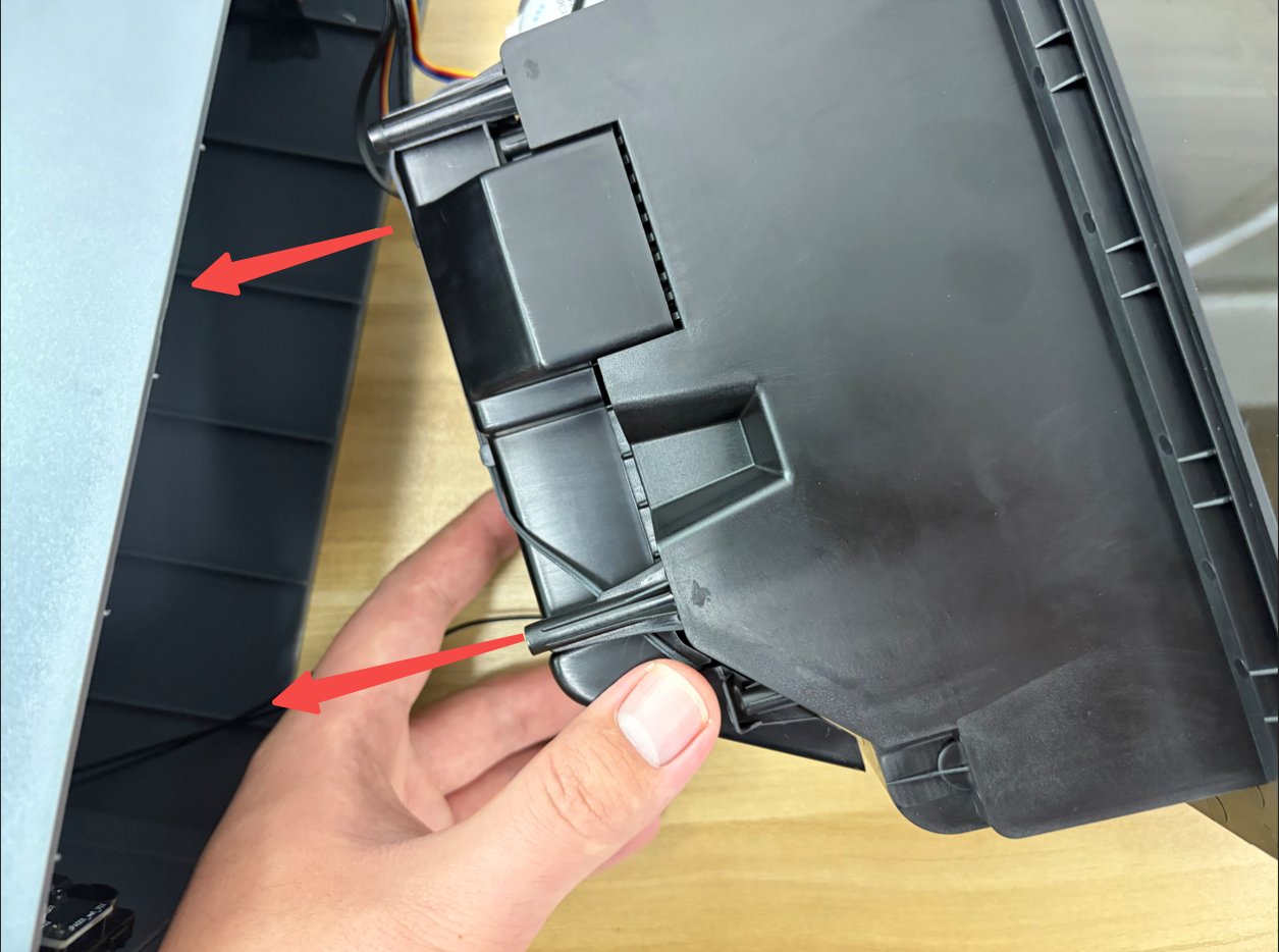
- Place it on the bottom cover assembly or another stable surface for subsequent operations.
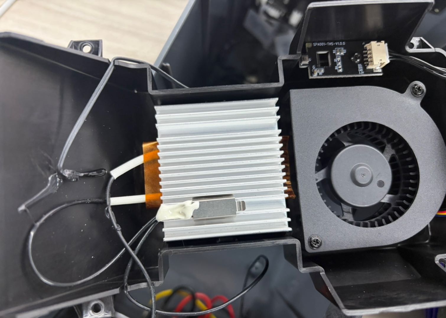
¶ Remove The PTC Assembly And Temperature Control Switch Fixing Part
- Use a screwdriver to gently pry up the PTC assembly and temperature control switch fixing part from the edge, then remove it.
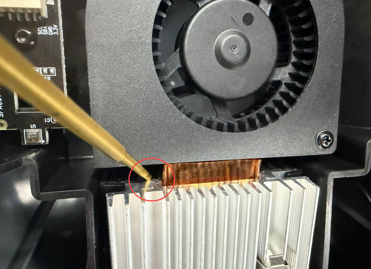
- After removing the PTC assembly and temperature control switch fixing part, place it on a level surface and remove the two PTC insulation pads.
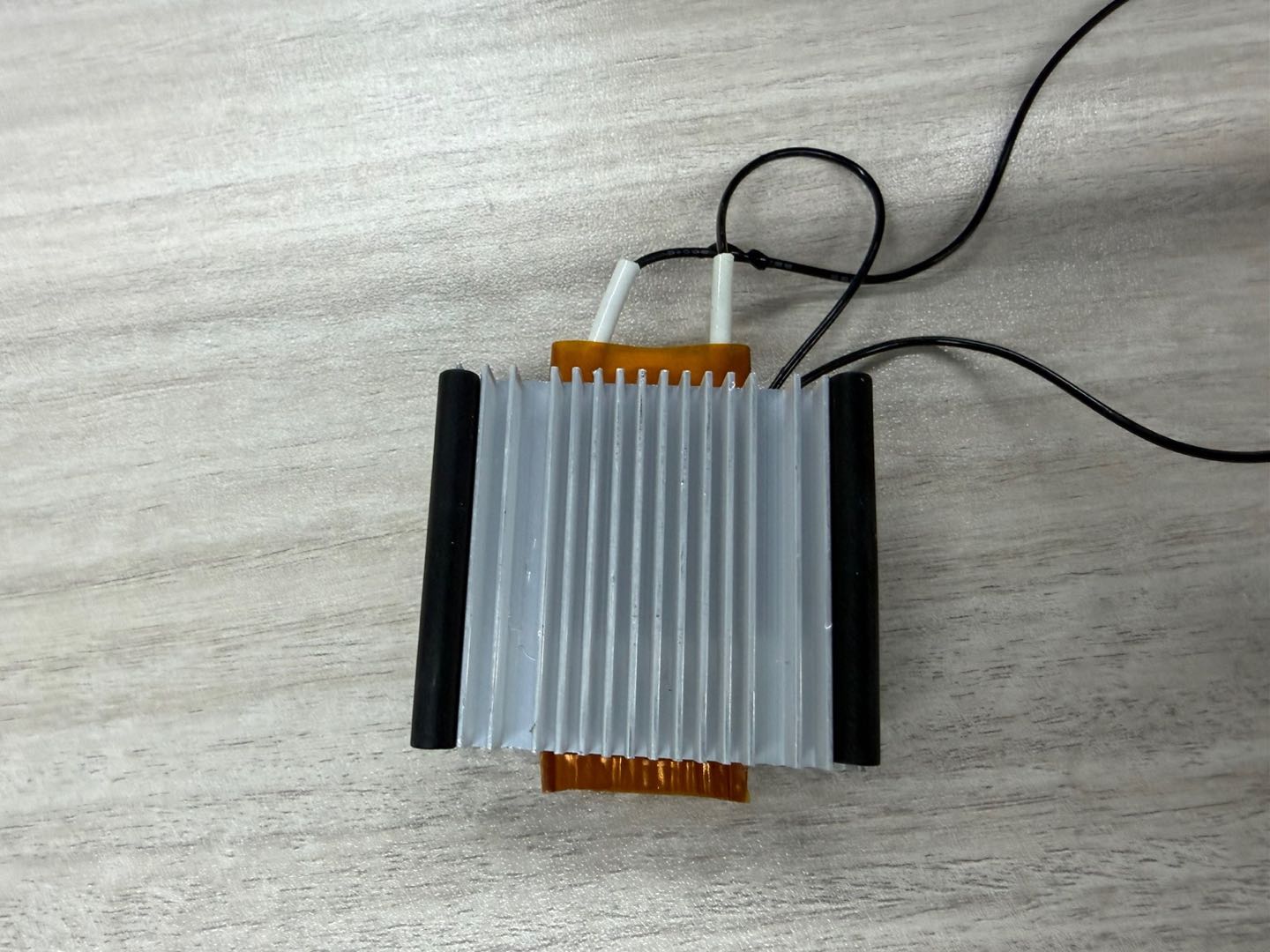
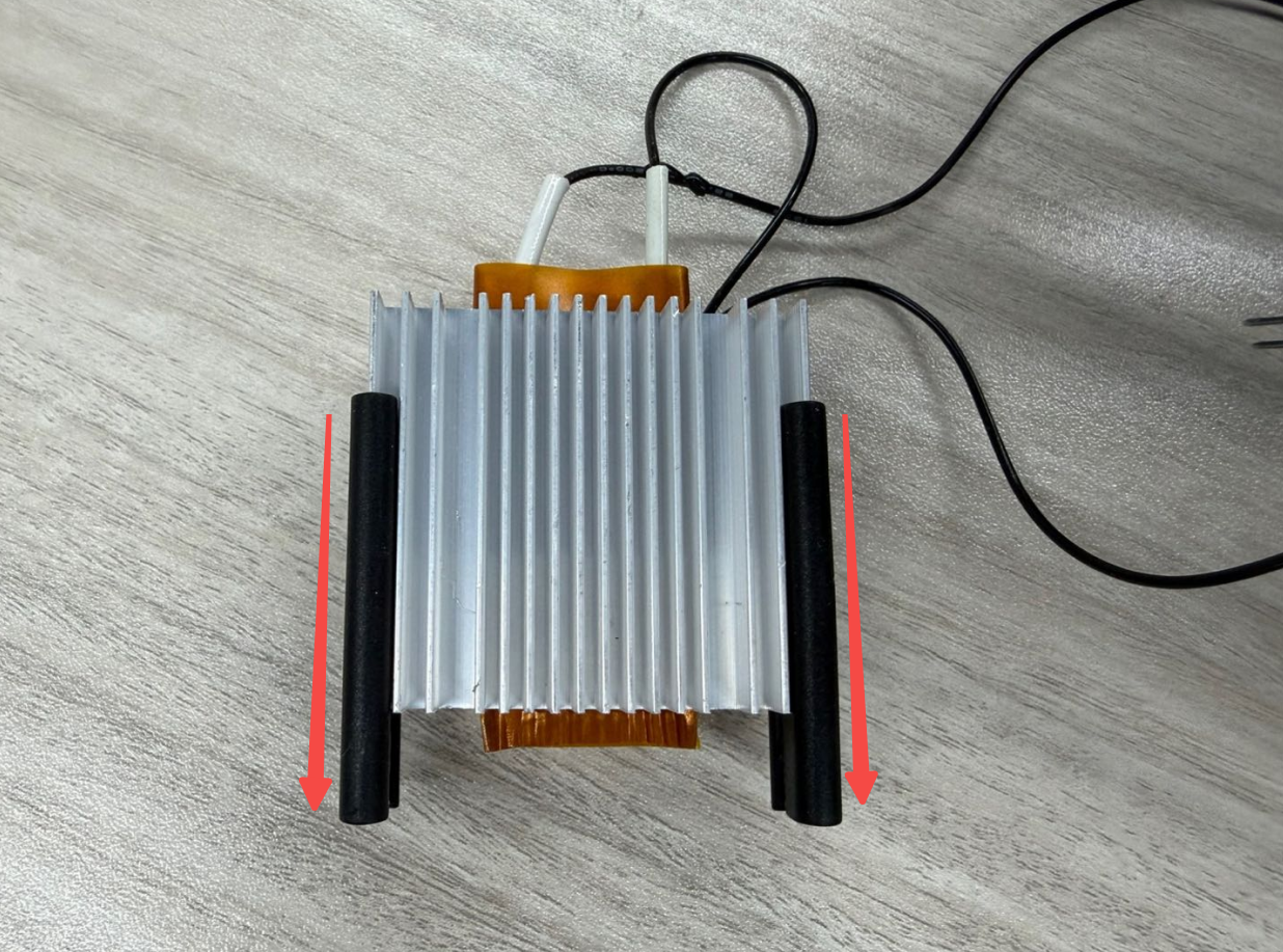
Tip: Push the PTC insulation pad forward to remove it.
¶ Installation Steps
¶ Install The PTC Assembly And Temperature Control Switch Fixing Part
- Take out the new PTC assembly and temperature control switch fixing part.
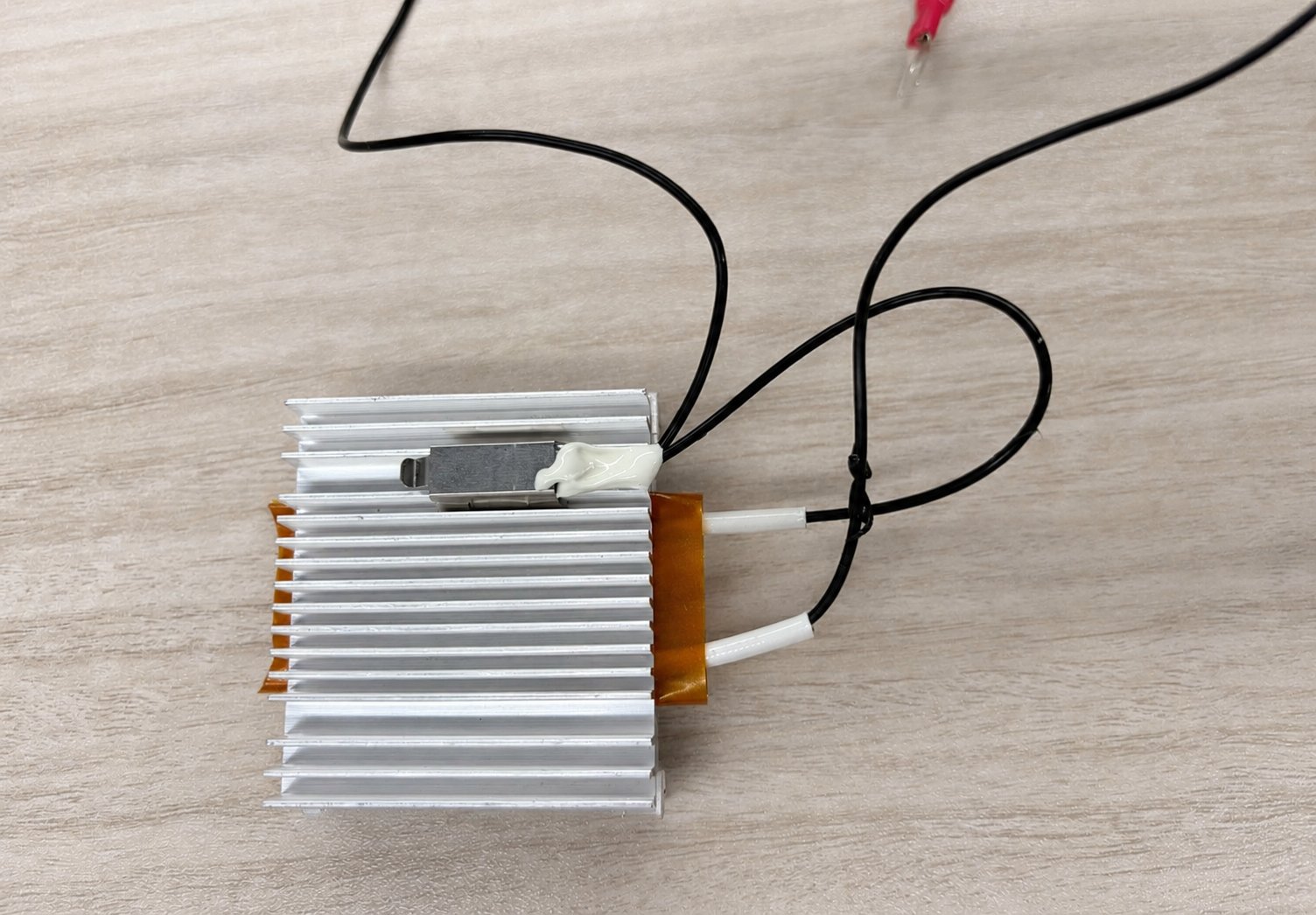
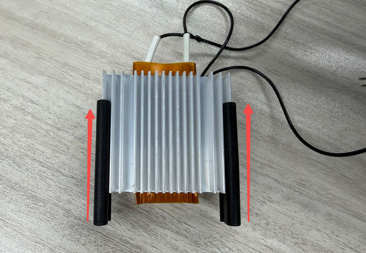
- Install the PTC insulation pads.
Tip: Push the PTC insulation pad backward along the direction of the installation groove to ensure it is fully secured in place.
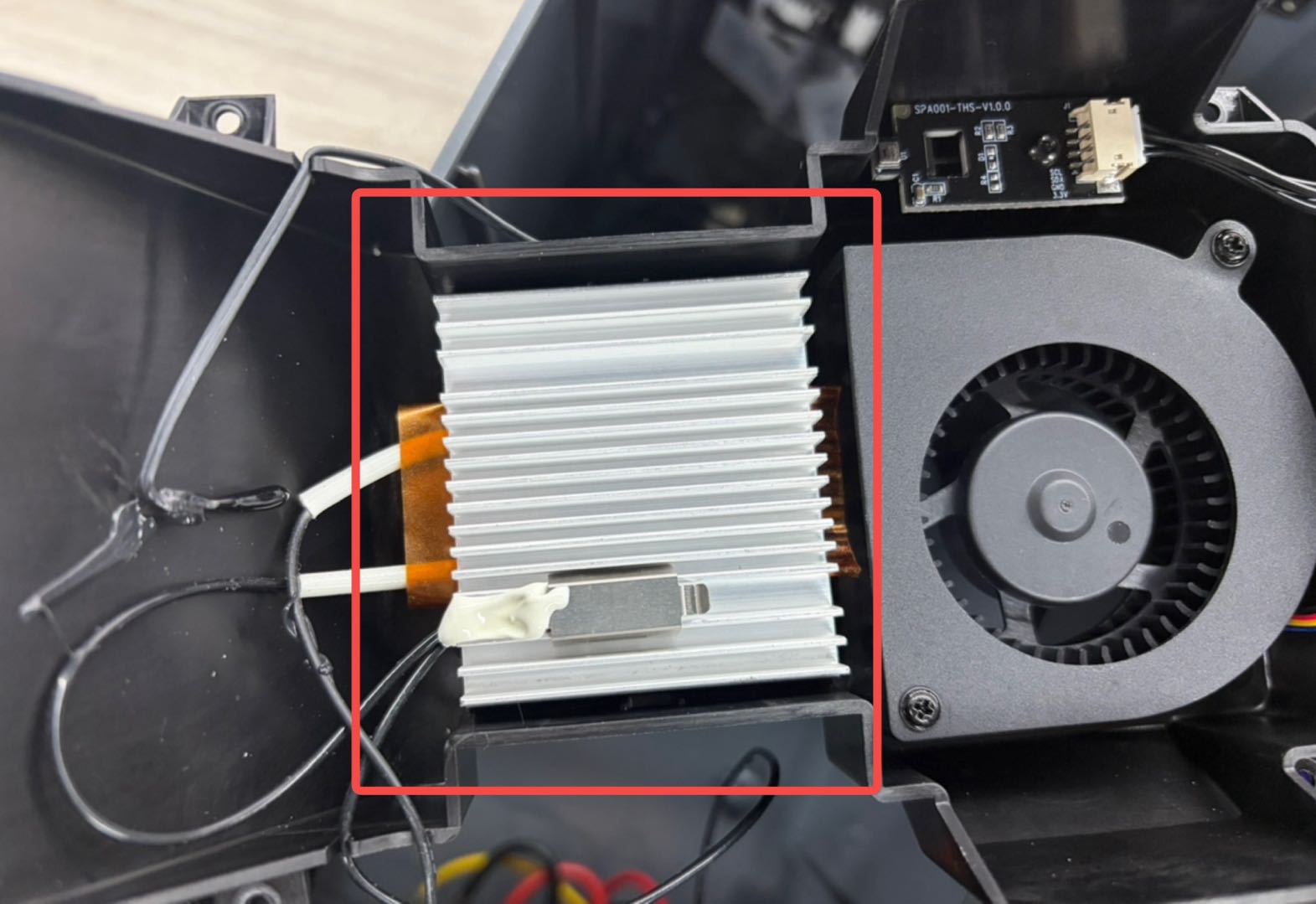
- Place it in the corresponding position on the air duct protection assembly.
¶ Install The Air Duct Protection Assembly
-
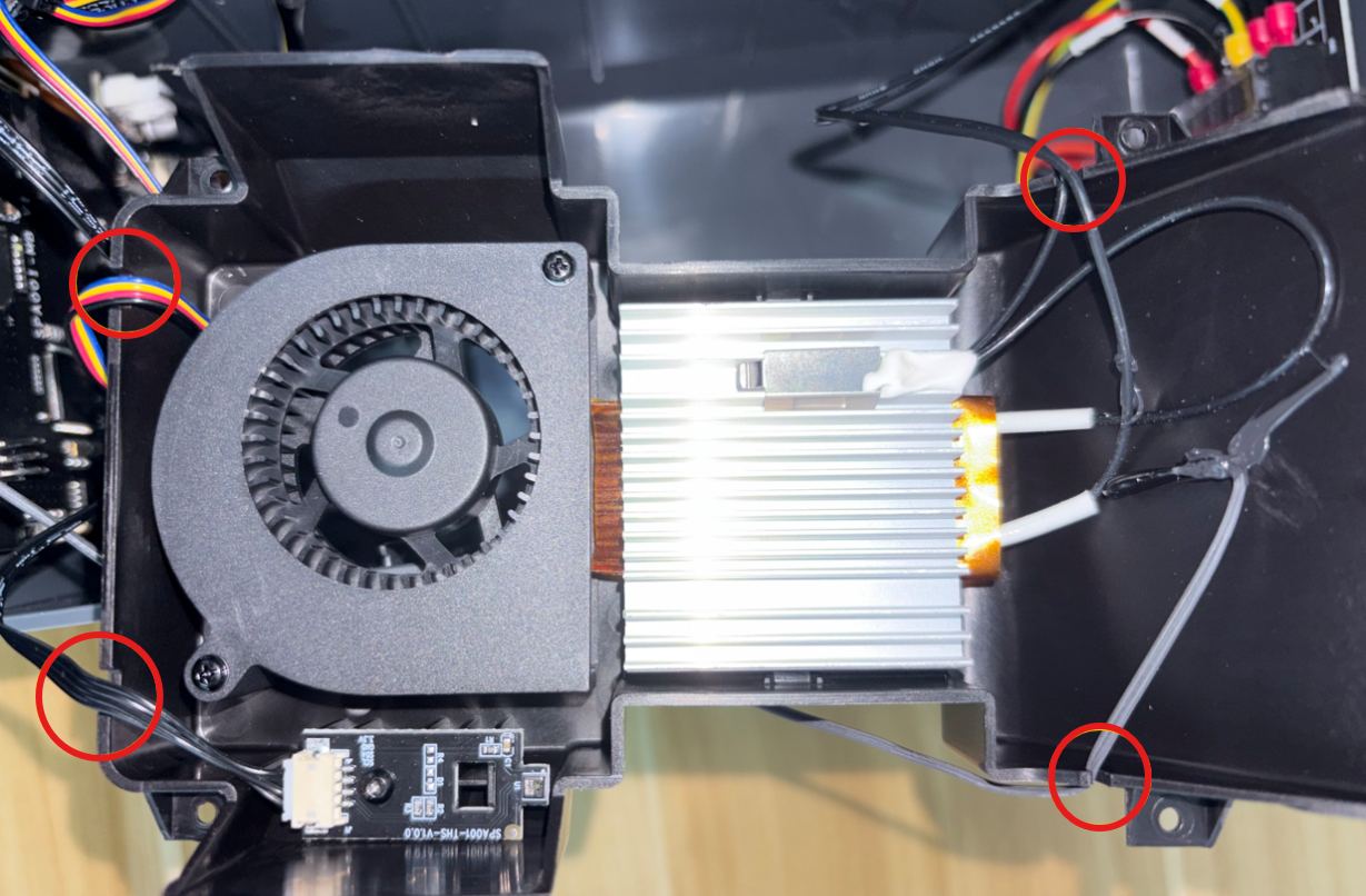
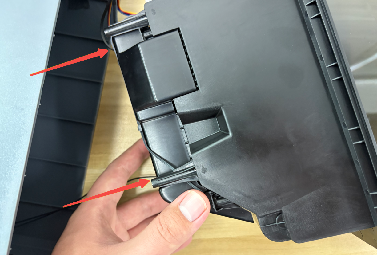
Arrange the wiring harness and place it into the cable groove on the edge of the air duct protection assembly to ensure the wiring harness is not pinched.
-
Slowly close the air duct protection assembly and confirm that the internal cables are not trapped.
-
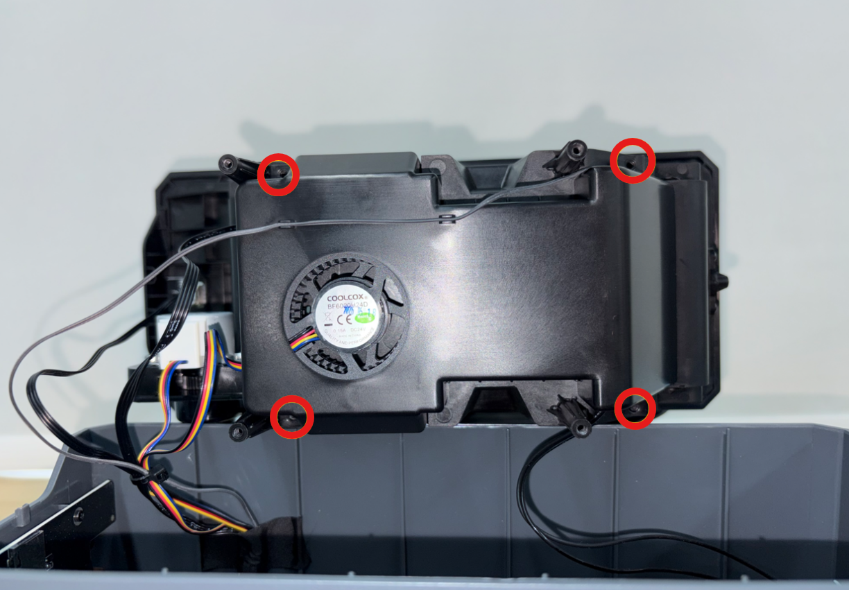
Use a 1.5 mm Allen Key to install the four screws securing the air duct protection assembly.
¶ Install The PTC Assembly Cables On The Power Supply Board Side
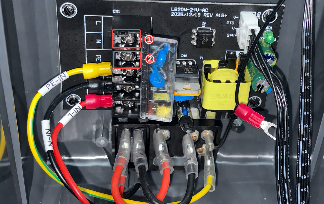
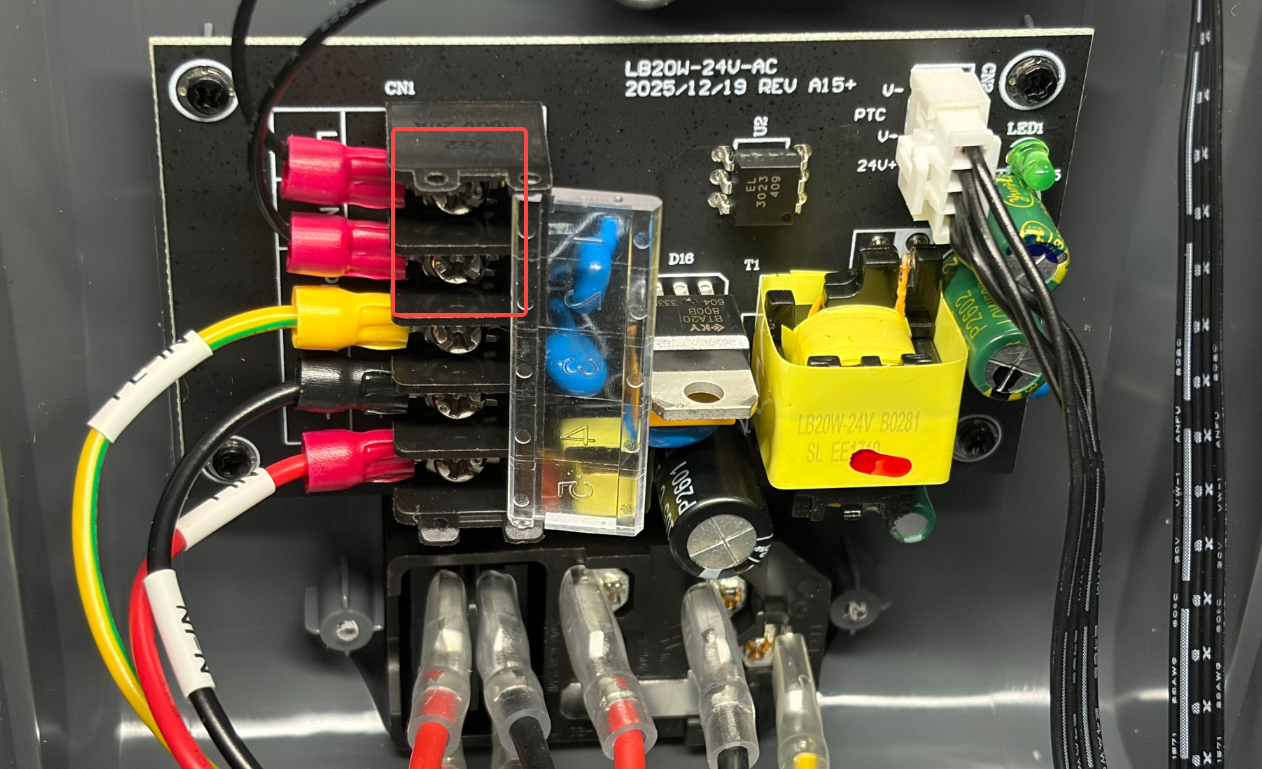
- Open the power cord protection cover. Install the two cables into the corresponding ports on the power supply board, then use a Phillips Screwdriver to tighten the screws securing cables ① and ②.
Note: The two cables of the PTC assembly are non-polarized and can be connected to the OUT-L and OUT-N ports on the power supply board respectively.
- Close the power cord protection cover.
¶ Secure The Bottom Cover
- Align the inner tray assembly with the installation position of the bottom cover and place it into position. Make sure the edges are fully fitted.
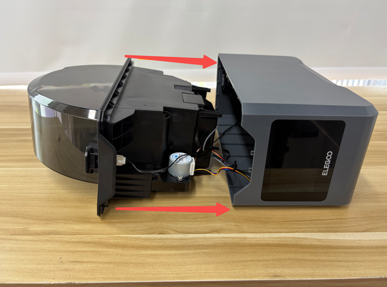
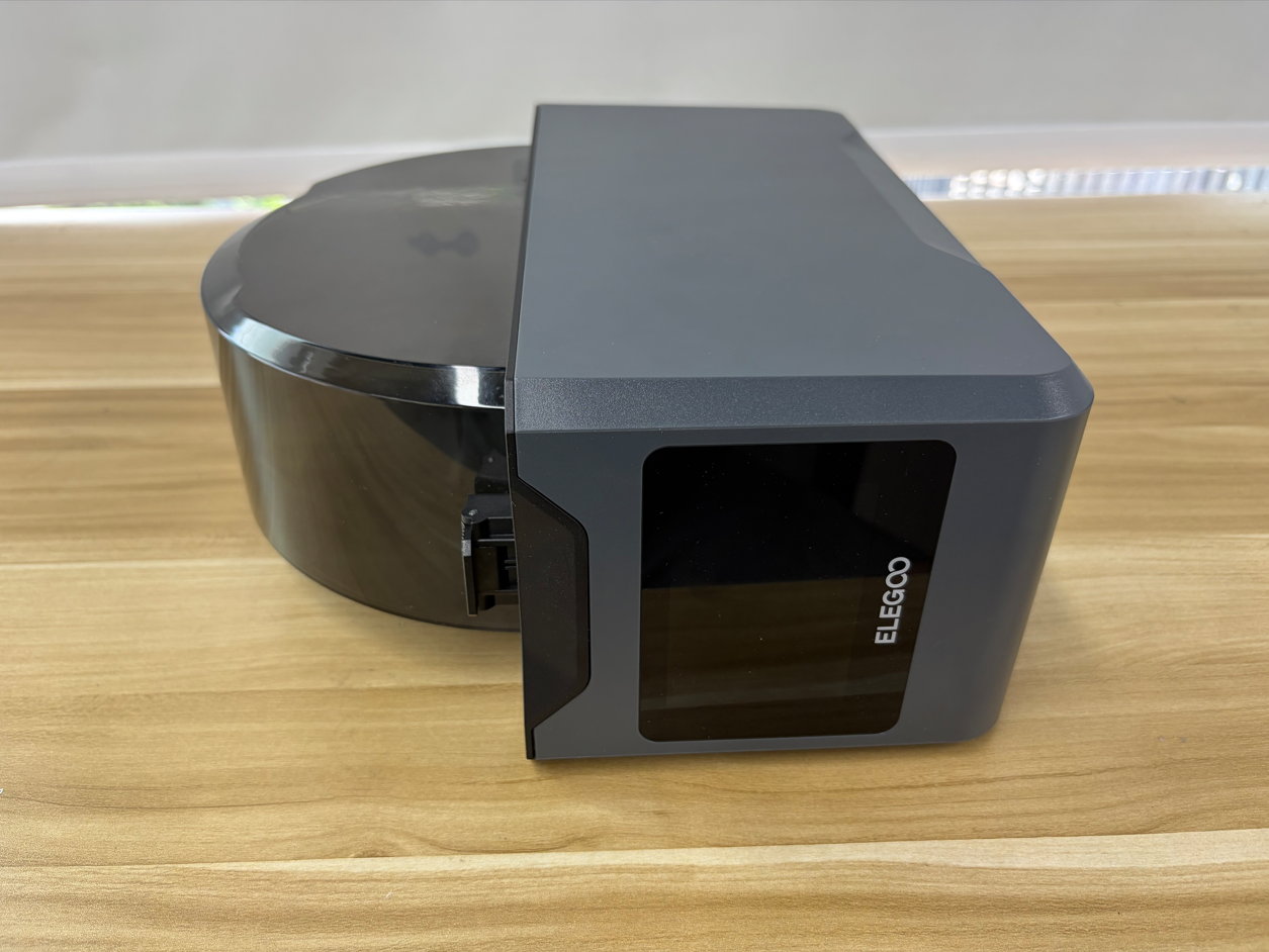
- Tighten the four screws, securing the bottom cover.
¶ Verification
-
Place the H1 HT upright.
-
Connect the power cord and turn on the power switch.
-
Wait for the touchscreen to start and confirm that the display works properly.
-
Go to the main interface and tap “Set Temp”.
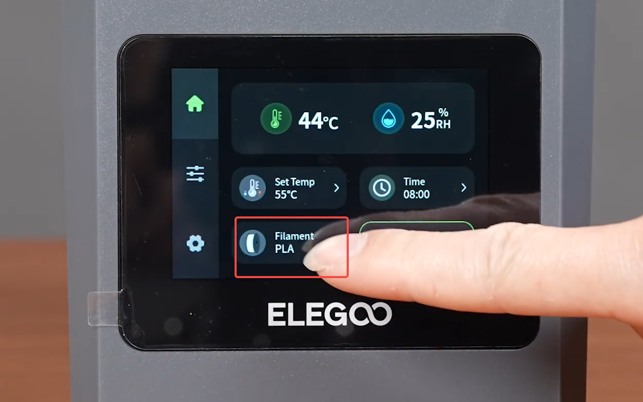
- Tap "+" to increase the temperature setting. Check whether the H1 HT can heat properly. Confirm that the temperature display remains stable and observe that no abnormal alarms occur during heating. The replacement is complete.
¶ Help Us Improve
If you have any ideas about the wiki pages, please let us know via ELEGOO official feedback channel