¶ Required Tools
2.5mm Allen Key
Phillips Screwdriver
New Power Supply Board
¶ Disassembly Steps
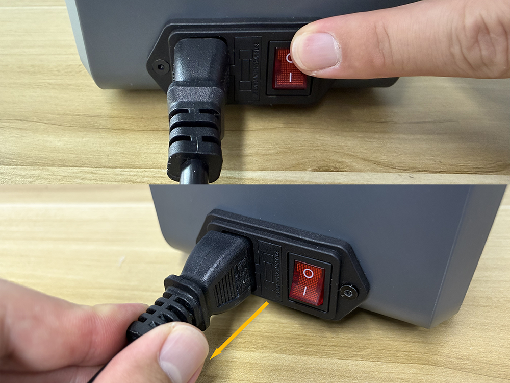
Warning: Before starting the operation, turn off the device power switch and unplug the power cord. Do not touch any exposed terminals or electrical components on the power supply board during the operation.
¶ Remove the Filament
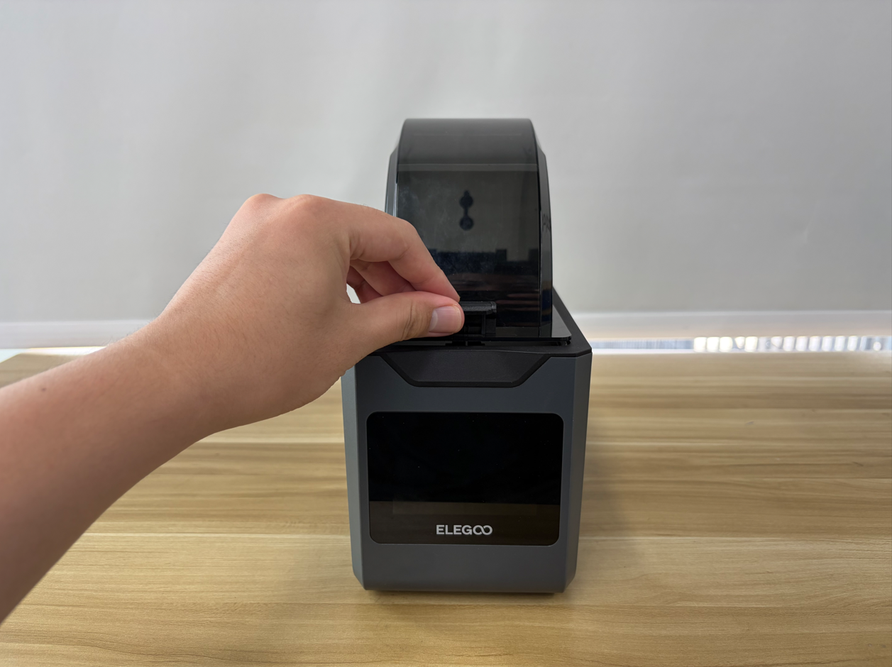
- Open the top cover.
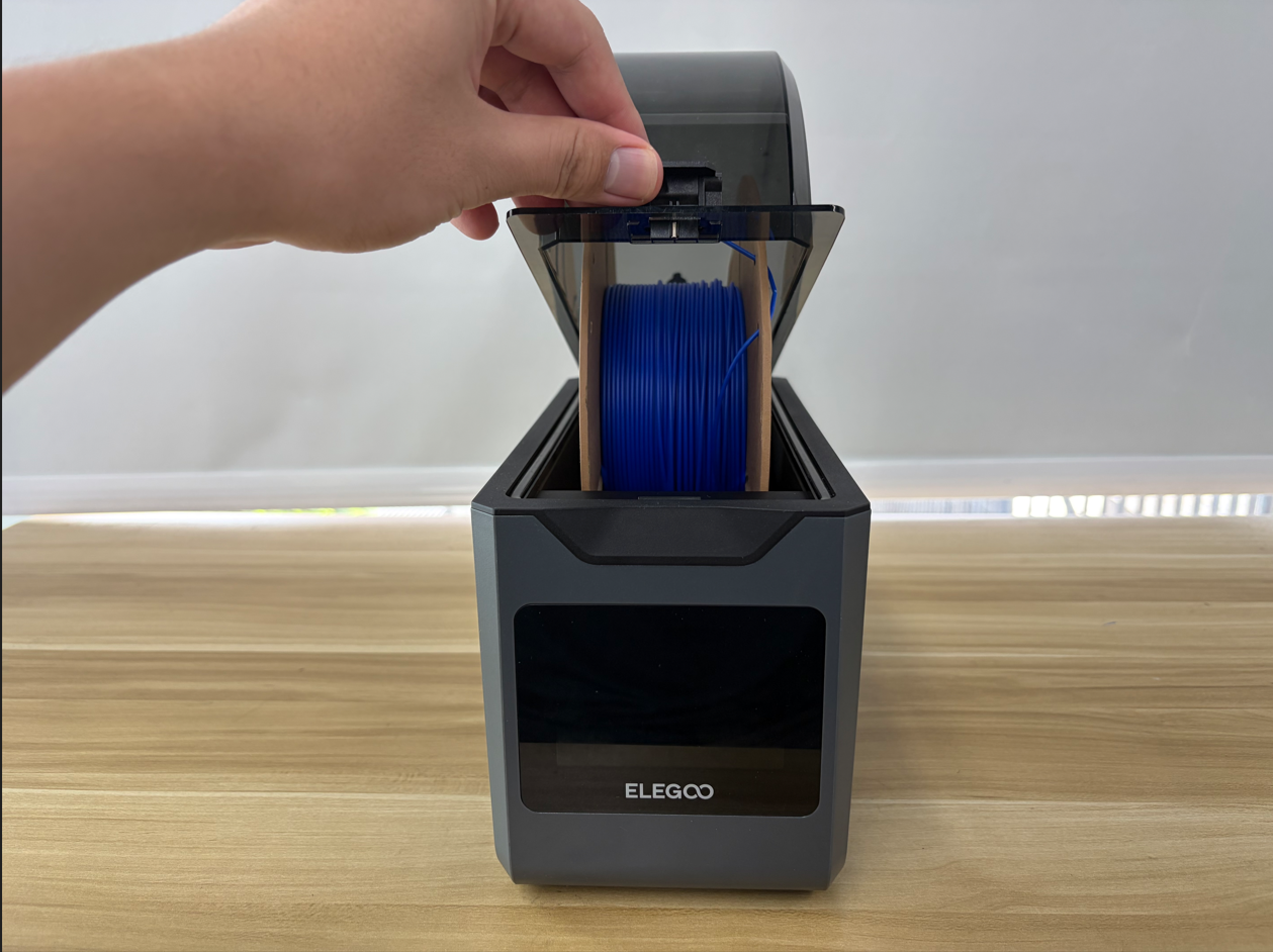
- Remove the filament.
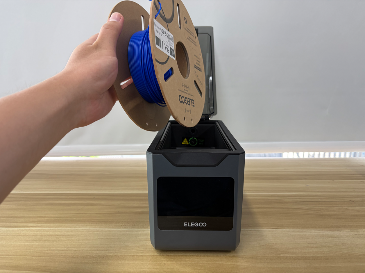
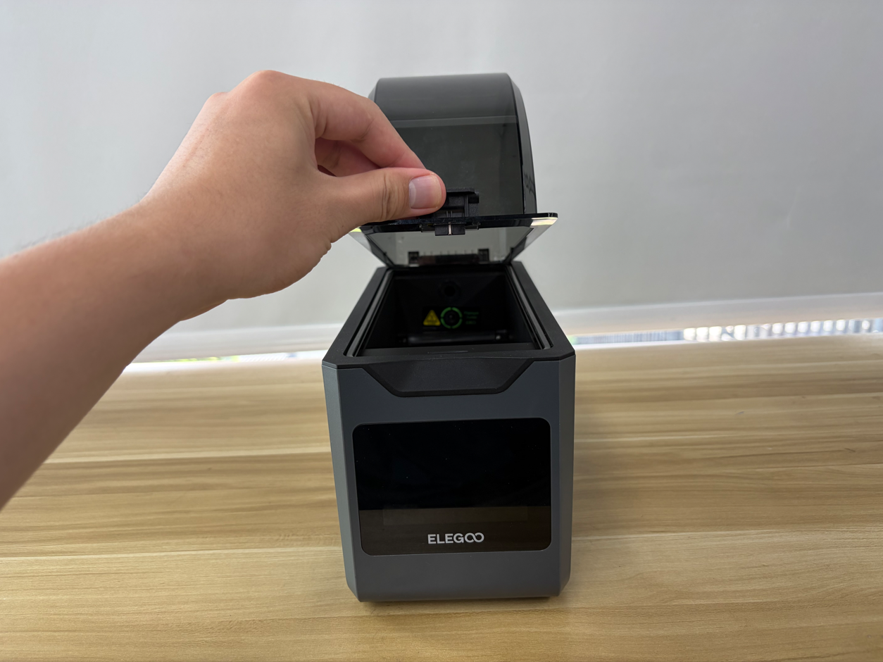
- Close the top cover.
¶ Open the Bottom Cover
- Place the H1 HT on its side on a level surface.
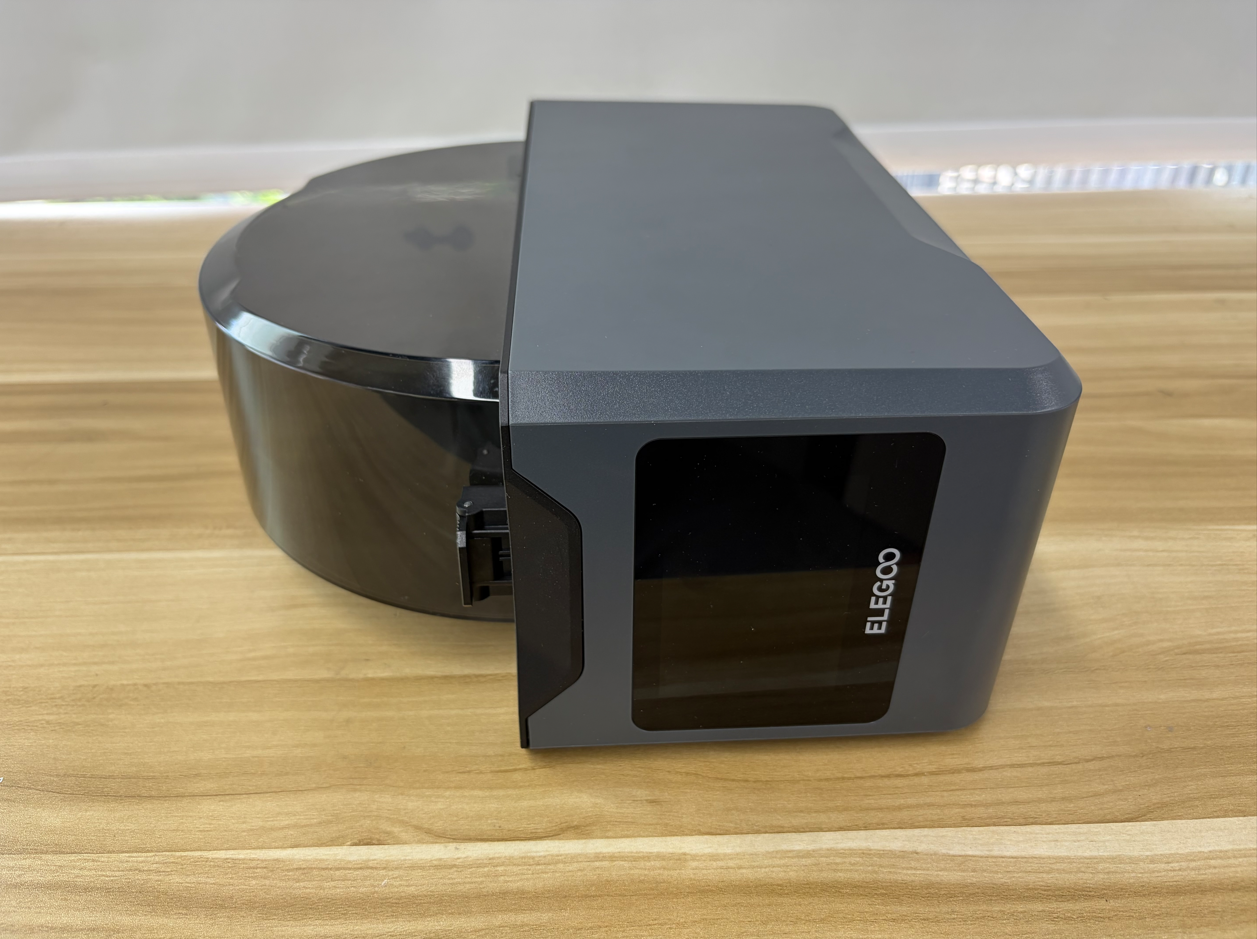
- Use a 2.5 mm Allen Key to remove the four screws securing the bottom cover.
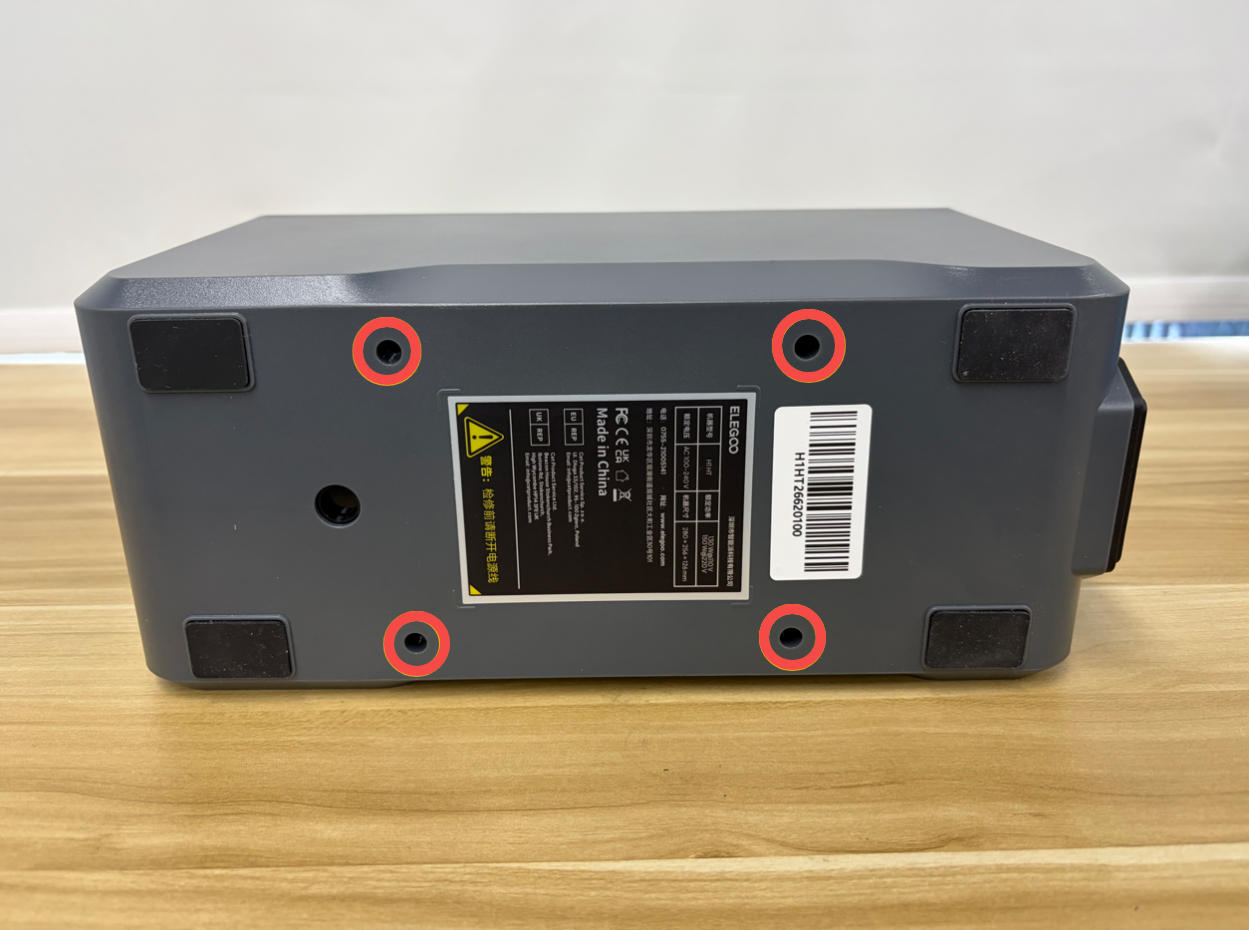
- Slowly open the bottom cover. Be careful not to pull or strain the internal cables.
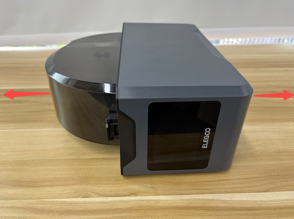
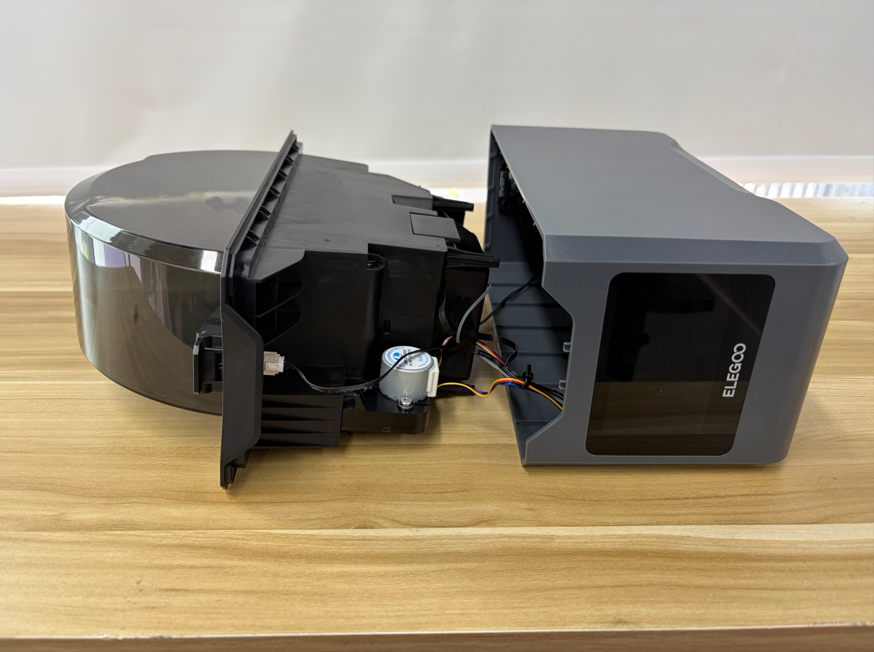
- Place the machine with the bottom side facing upward on a stable and level surface.
Tip: To facilitate the following operations, place the two filament spools under the inner tray assembly and top cover as supports.
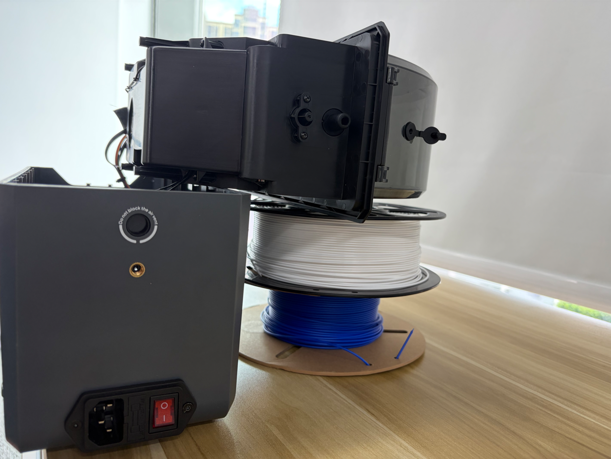
¶ Disconnect the Power Supply Board Cables
- Open the protective cover of the power supply board wiring area.
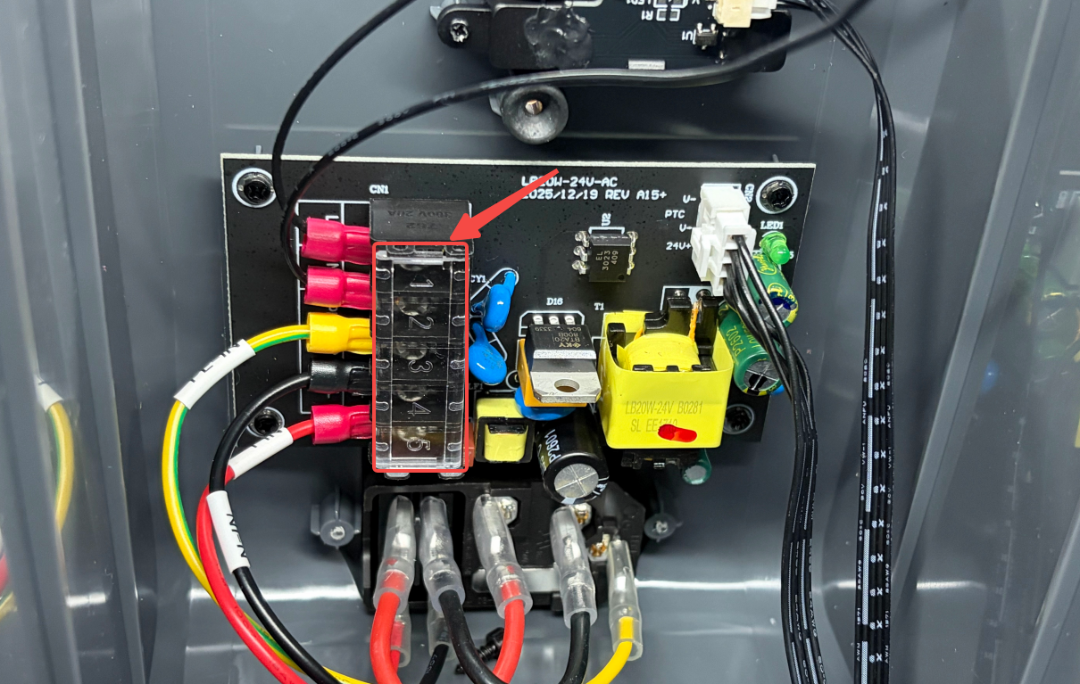
- Use a Phillips Screwdriver to loosen the five screws securing the power supply board cables. (Do not remove the screws completely.)
Note: After loosening the screws, confirm that the cables can be removed freely before proceeding to the next step.
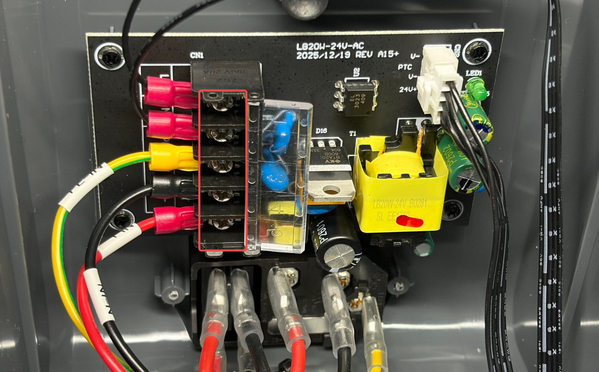
Note: Record the corresponding cable names and power supply board Port names below for subsequent installation.
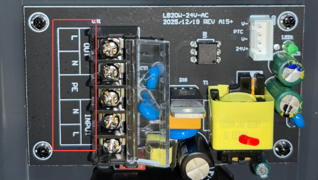
- Cable① and Cable② are PTC assembly cables with no polarity. They can be connected interchangeably to the OUT-L and OUT-N ports on the power supply board.
- The corresponding Port for the PE-IN yellow cable is: PE Ground Wire
- The corresponding Port for the N-IN black cable is: INPUT-N Neutral Wire
- The corresponding Port for the L-IN red cable is: INPUT-L Live Wire
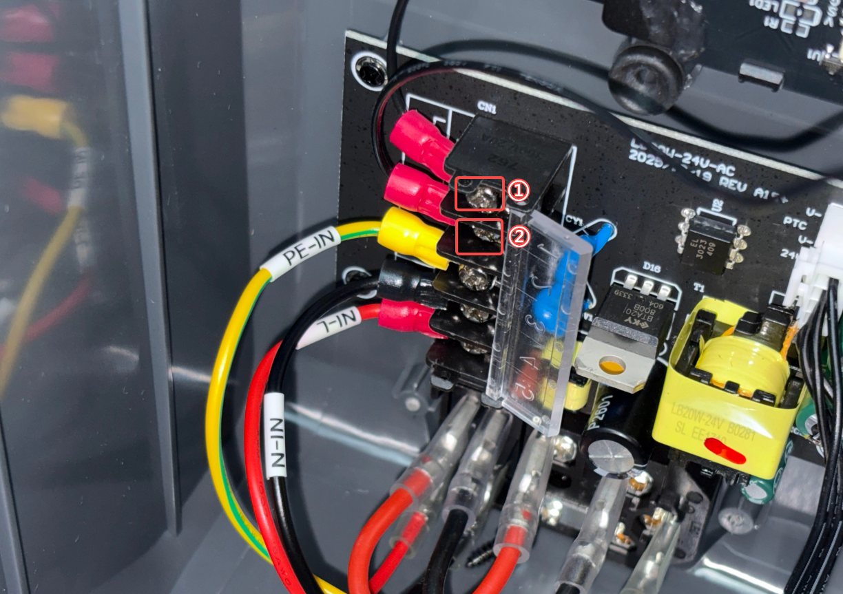
- Remove the cables one by one.
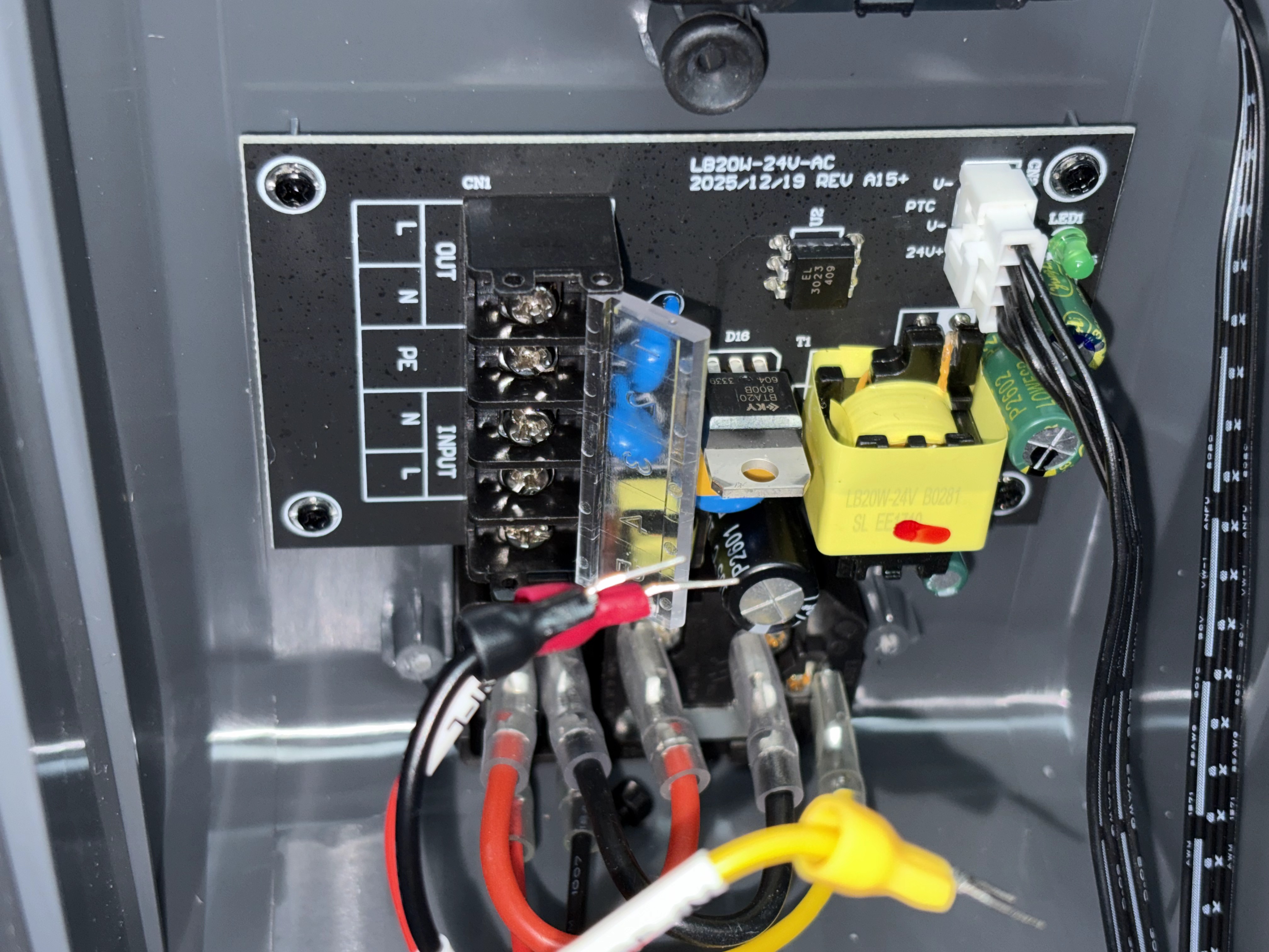
5. Disconnect the cable connecting the power supply board to the mainboard.
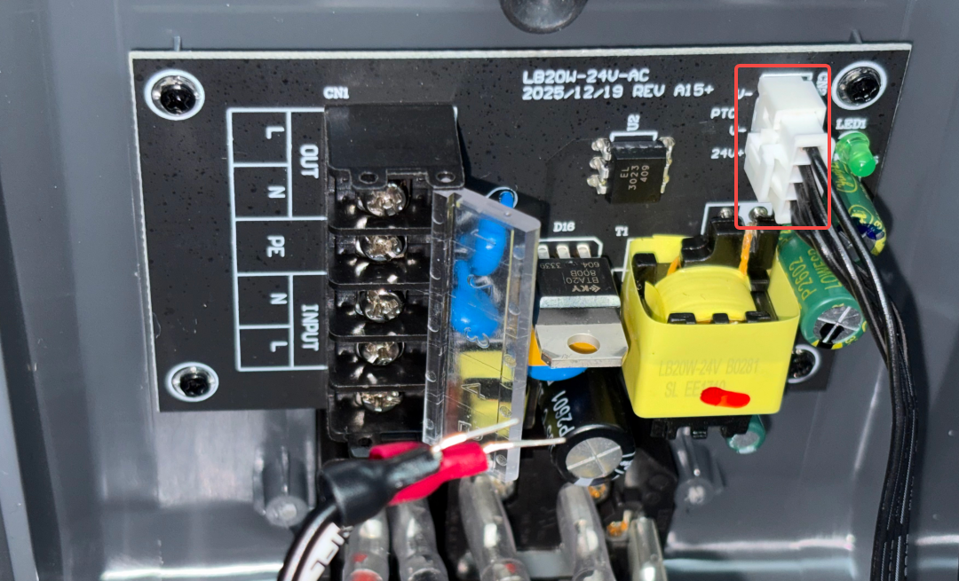
¶ Remove the Power Supply Board
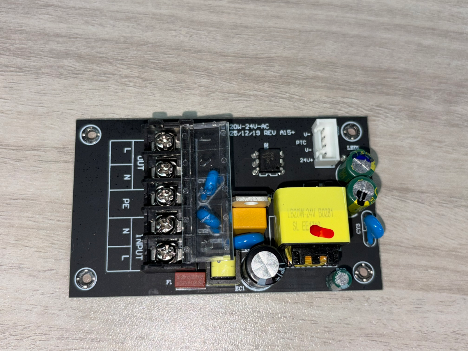
- Use a Phillips Screwdriver to remove the four screws securing the power supply board.
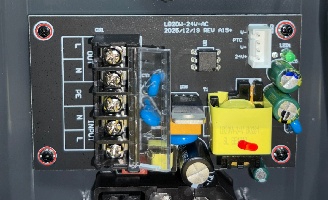
- Carefully remove the power supply board. Avoid contacting surrounding components or pulling other cables.
¶ Installation Steps
¶ Install the Power Supply Board
- Remove the new power supply board from its packaging.
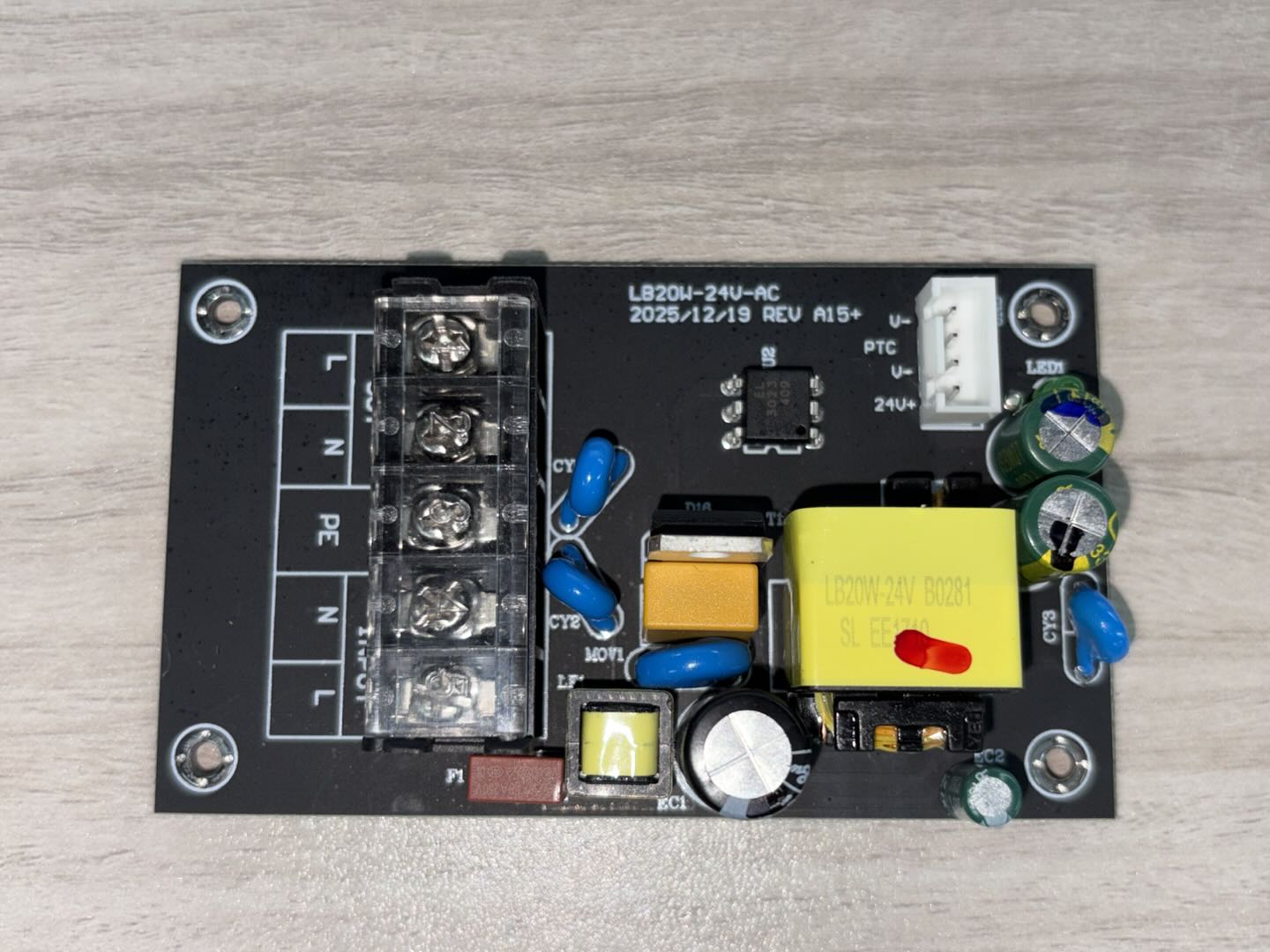
- Use a Phillips Screwdriver to install and tighten the four screws securing the power supply board, then open the protective cover of the power supply board wiring area.
¶ Install the Power Supply Board Cables
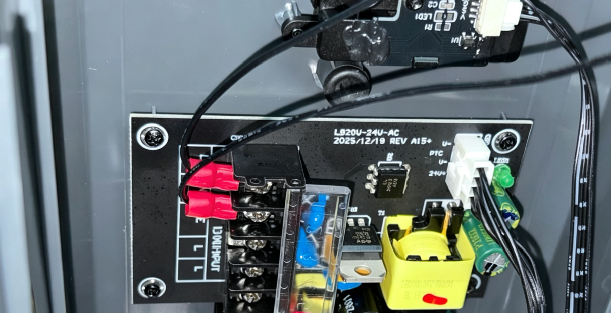
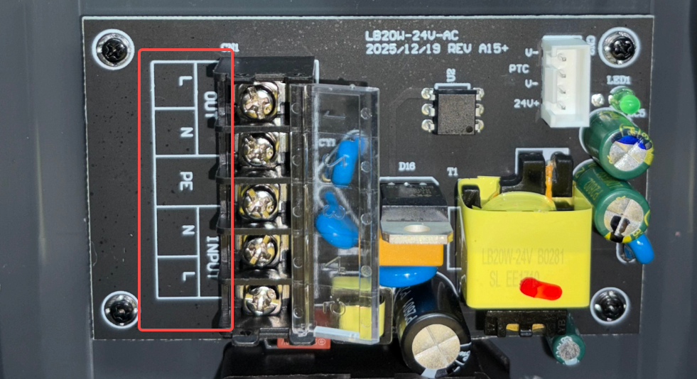
Tip: When installing the cables, refer to the Port labels on the power supply board shown below to ensure that each cable is installed in the correct position. Make sure the copper terminals are fully inserted into the terminal blocks, and tighten the screws securely to ensure a reliable connection.
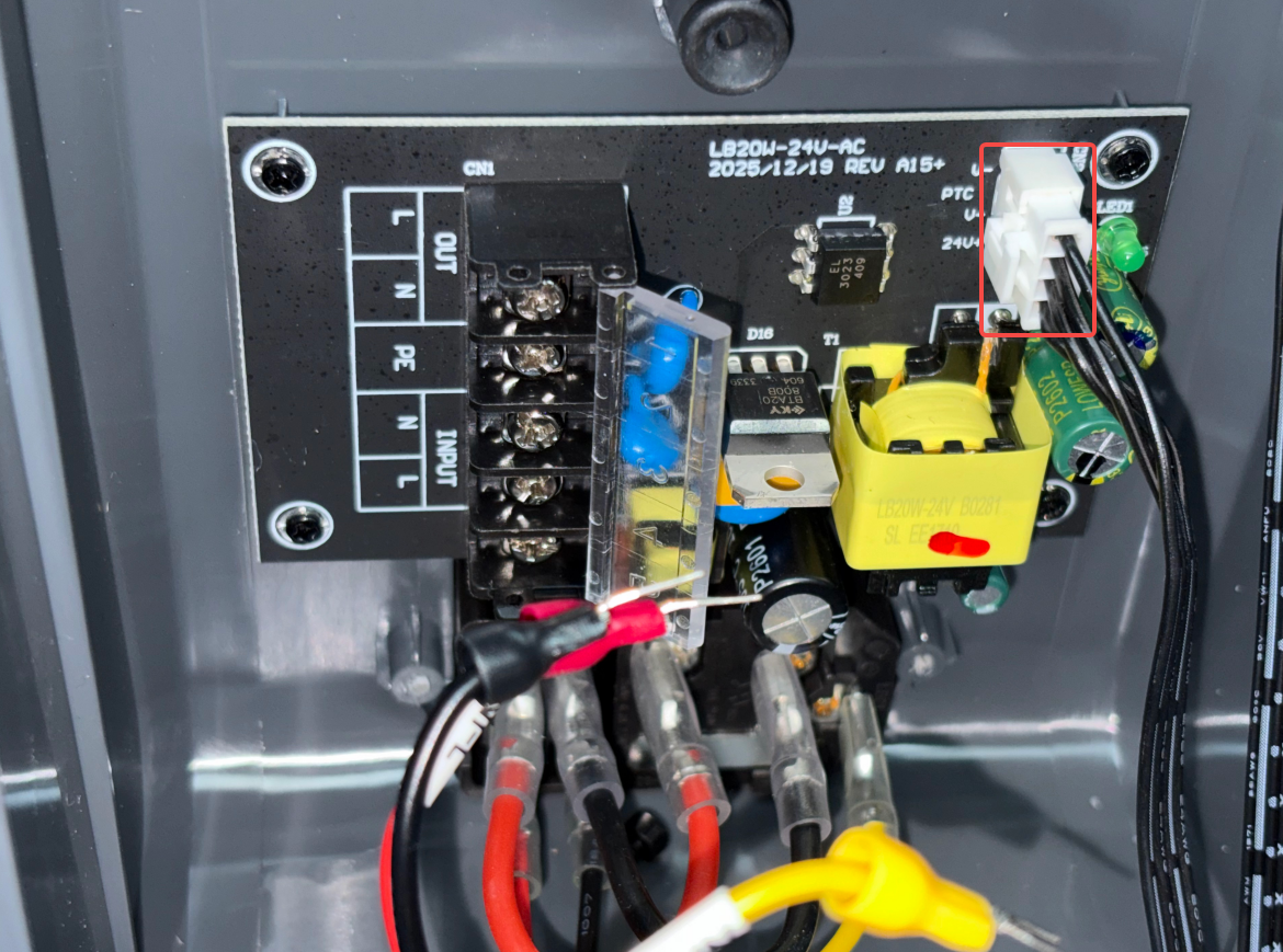
- Install the cable connecting the power supply board to the mainboard.
- Install the two PTC assembly cables to the OUT-L and OUT-N ports on the power supply board, respectively, and tighten the screws with a Phillips screwdriver.
Note: The two cables are non-polarized, so either cable can be connected to the OUT-L or OUT-N port on the power supply board.
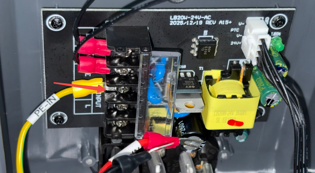
- Install the PE-IN yellow cable back into the power supply board PE Ground Wire Port, and tighten the screw with a Phillips Screwdriver.
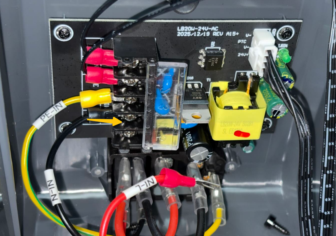
- Install the N-IN black cable back into the power supply board INPUT-N Neutral Wire Port, and tighten the screw with a Phillips Screwdriver.
- Install the L-IN red cable back into the power supply board INPUT-L Live Wire Port, and tighten the screw with a Phillips Screwdriver.
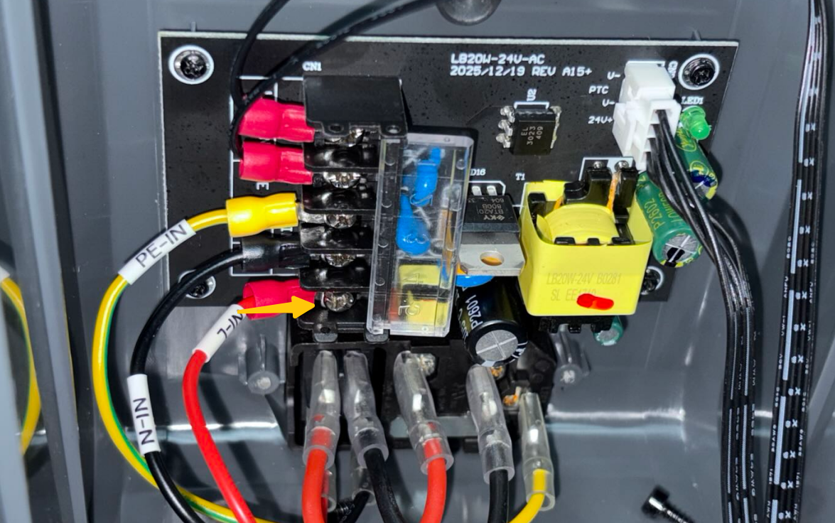
- After tightening the terminal screws, refer to the following image and the cable labels again to confirm that all cables are connected to the correct power supply board ports.
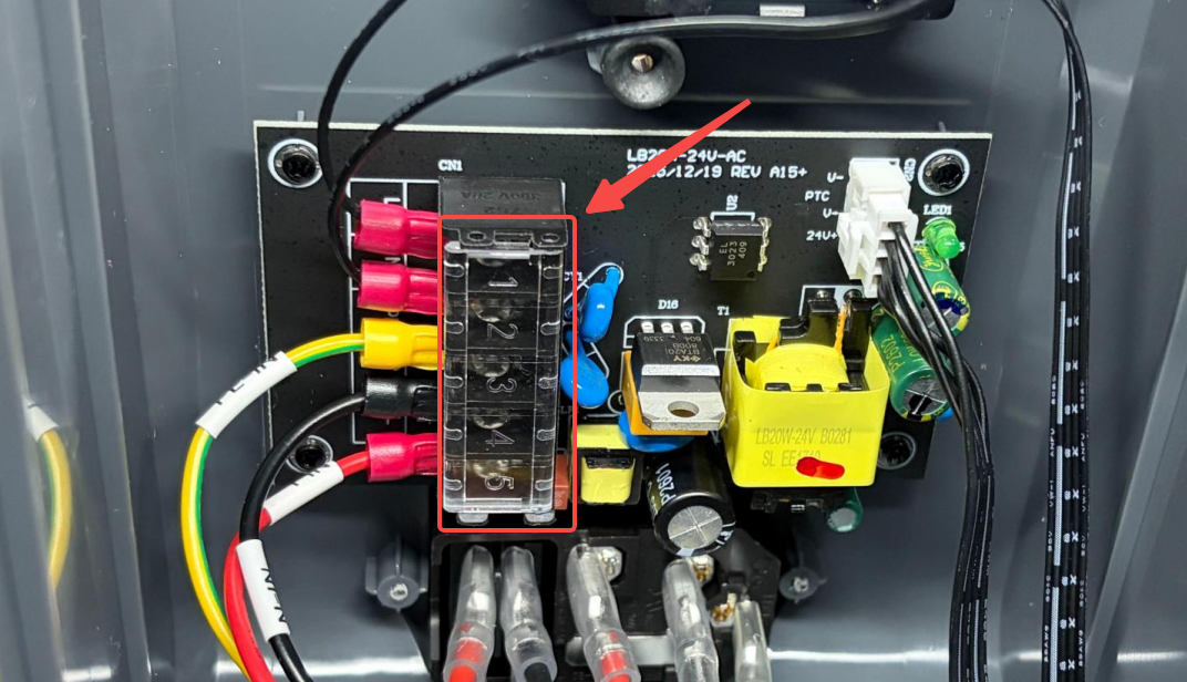
- Close the protective cover of the cable connection area.
¶ Install the Bottom Cover
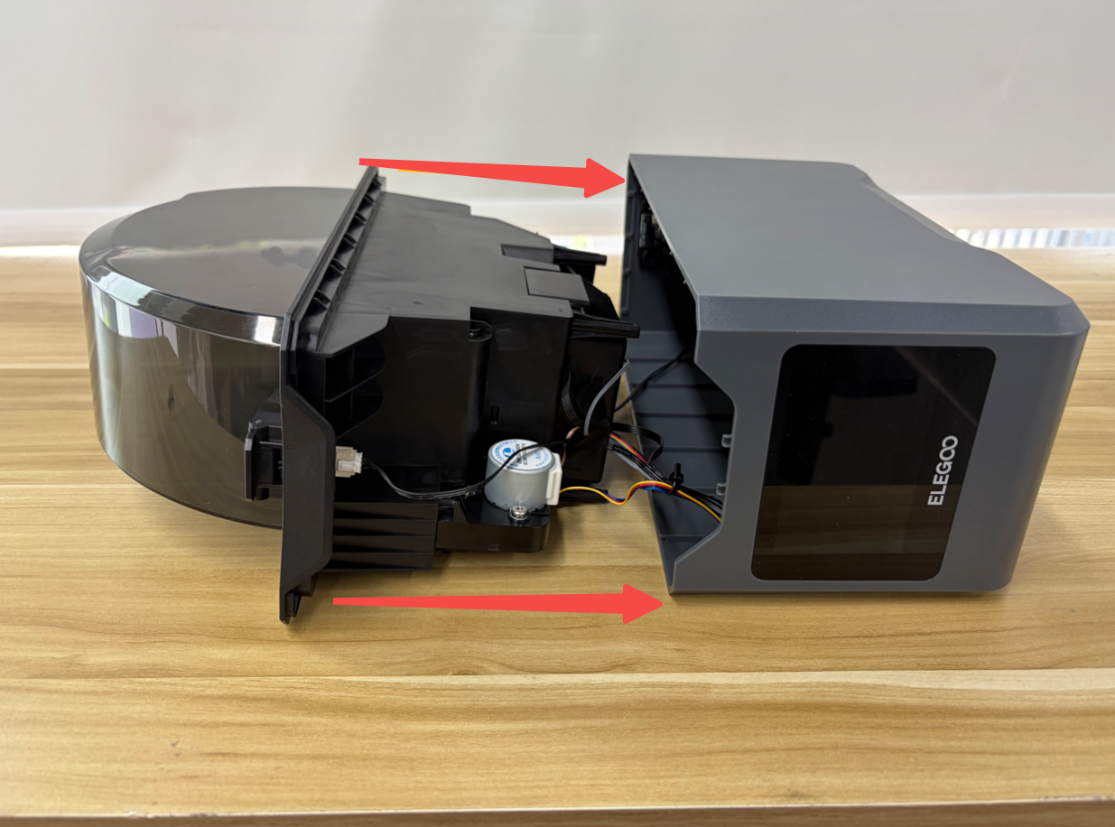
- Align the inner tray assembly with the positioning points of the bottom cover, and place it back inside the bottom cover.
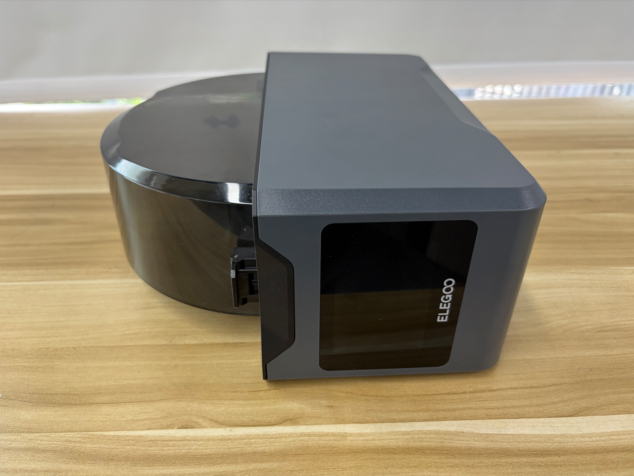
- Tighten the four screws, securing the bottom cover.
¶ Verification
- Place the H1 HT upright.
- Connect the power cord and turn on the power switch.
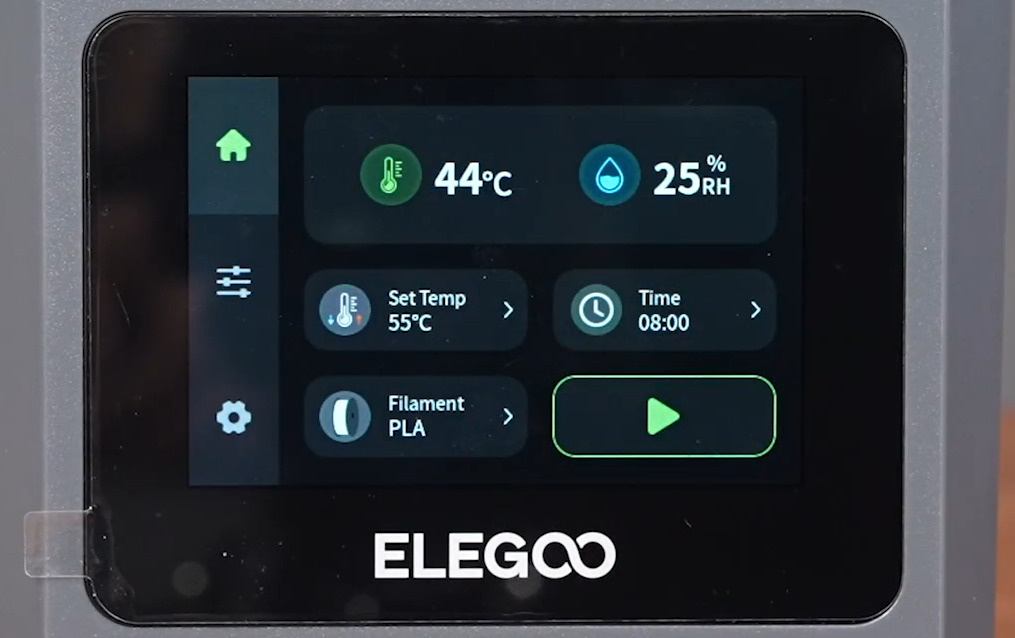
- Wait for the touchscreen to start up and confirm that the display works properly.
- Confirm that the device enters the main interface normally and that there are no abnormal prompts, noises, odors, or overheating during operation. The power supply board replacement is complete.
¶ Help us improve
If you have any suggestions or feedback about the wiki pages, please let us know through the ELEGOO official feedback channel.