¶ Fault Symptoms
- After printing is completed, there is no cured resin on the build plate or in the resin tank.
- When LCD exposure is enabled through the touch screen, the LCD screen displays normally, but the UV light does not turn on.
¶ Possible Causes
- An adapter with incorrect specifications is used.
- The connector on the constant-current board is loose.
- The UV light board or constant-current board is faulty.
- The UV power output from the mainboard is abnormal.
¶ Tools Required
- 2.0 mm Allen key
- Multimeter
¶ Troubleshooting Steps
Note: Before troubleshooting, open the UV Cover and remove the build plate and resin tank.
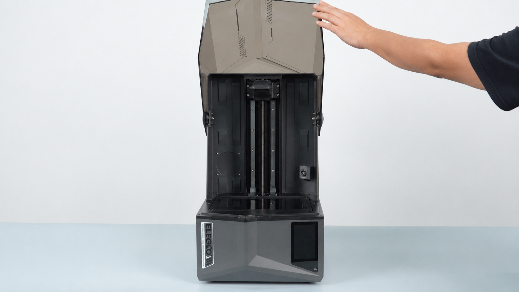
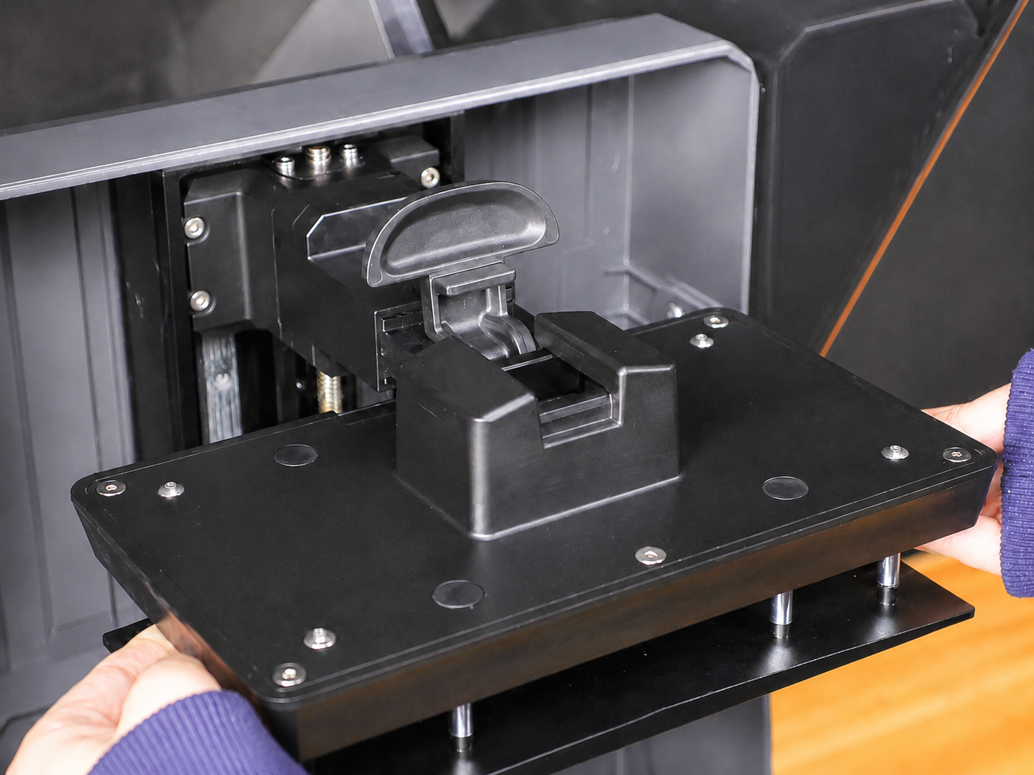
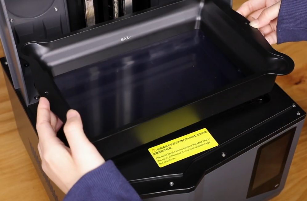
¶ 1. Check the Adapter Specifications
- Check the specification information on the back of the adapter. The default adapter specifications for the Saturn 4 Ultra and Saturn 4 Ultra 16K are 24 V, 6 A.
- If the adapter specifications are incorrect, replace it with an adapter that meets the required specifications.
- If the adapter specifications are correct, continue with the following troubleshooting steps.
Note: Adapters used with the MERCURY series typically have an output voltage of 12 V. Using a 12 V adapter with the Saturn 4 Ultra or Saturn 4 Ultra 16K will prevent the UV light from operating properly.
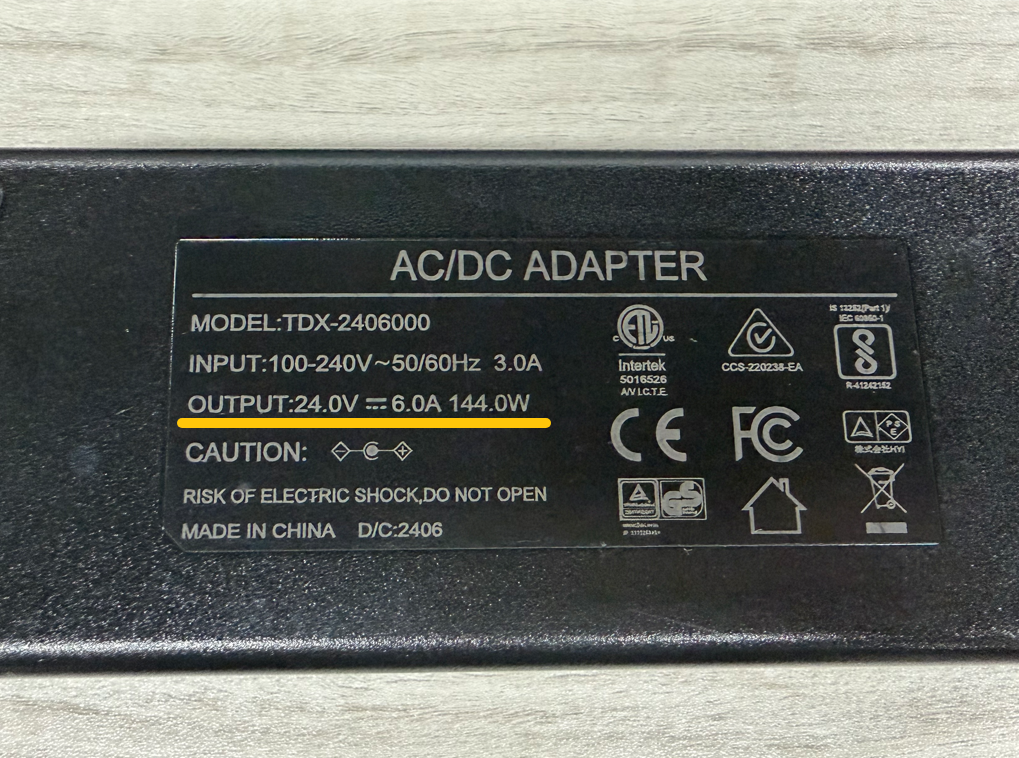
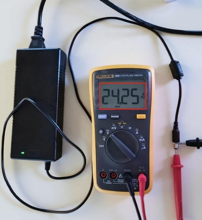
- If a multimeter is available, measure the adapter output voltage and confirm that it is 24 V. If a multimeter is not available, skip this step.
¶ 2. Check the Connector for Looseness
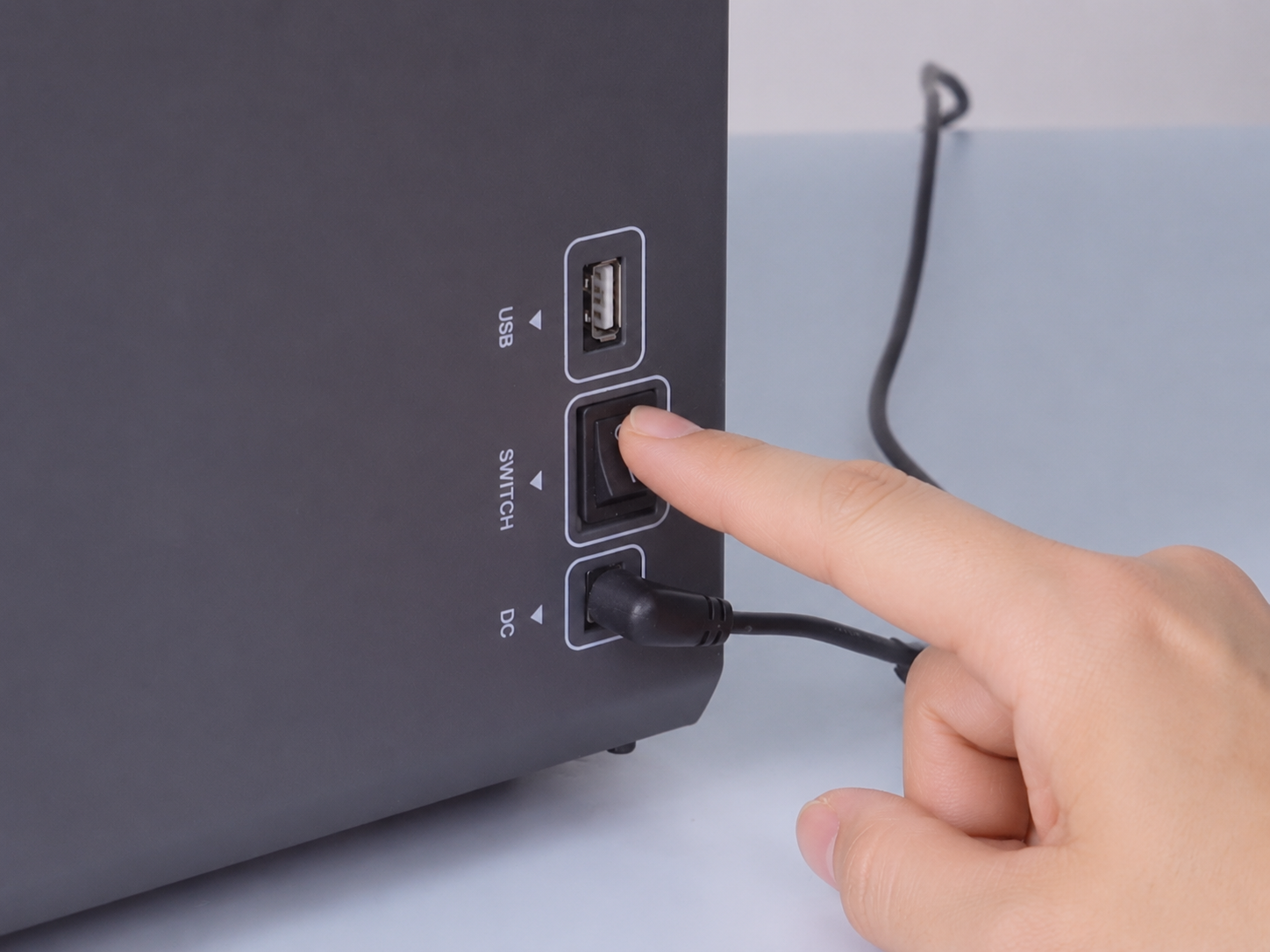
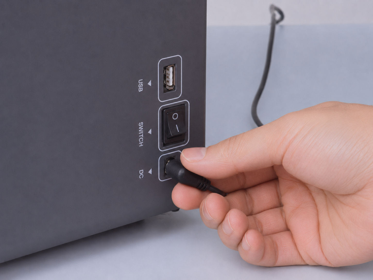
- Turn off the printer using the Power Switch and disconnect the adapter.
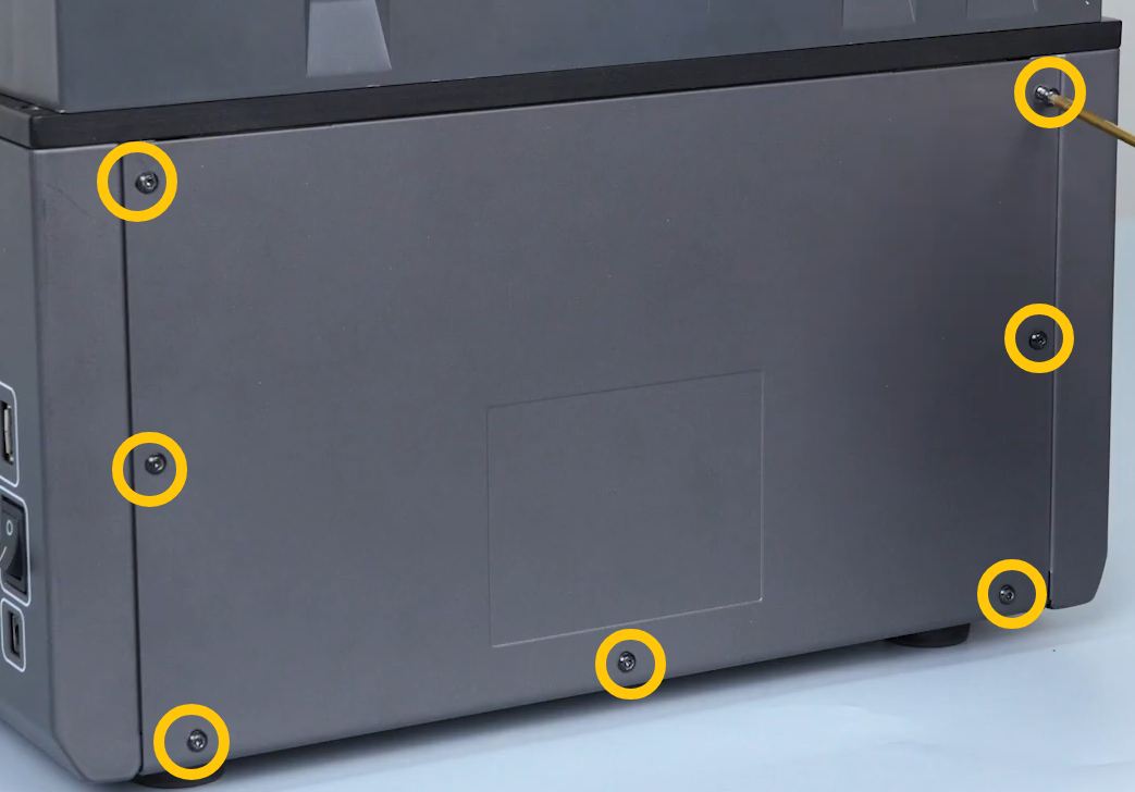
- Use a 2.0 mm Allen key to remove the seven screws securing the rear panel, and then remove the rear panel.
- Check whether the connector at the marked location is loose.
Note: The UV light connector is secured with hot-melt glue. If the connector is not loose, do not remove the hot-melt glue.
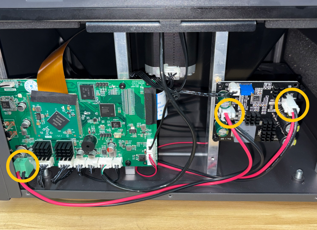
- If the UV light connector shows signs of burning, turn off the printer using the Power Switch, disconnect the adapter, and contact Technical Support with photos of the affected area. Do not use the printer until further instructions are provided.
- If the connector is loose, reconnect it securely.
- If the connector is not loose, continue with the following troubleshooting steps.
¶ 3. Check the Mainboard UV Power Output
Note: This step requires experience using a multimeter. If you are not familiar with using a multimeter, skip this step.
- Reconnect the adapter and turn on the printer.
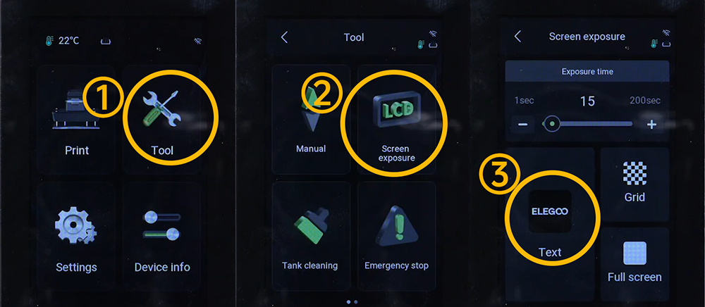
- On the touch screen, tap Tool > Screen Exposure > Text to enable LCD exposure.
- Use a multimeter to measure the voltage at the UV light connector.
Note: If you do not have a multimeter, skip this step. When measuring voltage, be careful not to touch other electronic components to avoid causing a short circuit.
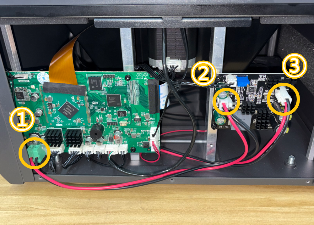
Note: Under normal conditions, the output voltage at points ① and ② should be approximately 24 V, while the output voltage at point ③ should be approximately 25 V.
- If there is no output voltage at ①, the mainboard may be faulty.
- If output voltage is present at ①, but not at ②, the connector at ② on the adapter cable may still be loose or have poor contact.
- If there is output voltage at ① and ②, but no output voltage at ③, the constant-current board may be faulty.
- If output voltage is present at points ①, ②, and ③, but the UV light does not turn on, the UV light board may be faulty.
¶ Contact Technical Support
If the issue persists after completing all the troubleshooting steps above, contact Technical Support at 3dp@elegoo.com and provide the following information:
- Inspection result — Whether the adapter specifications are correct.
- Inspection result — Whether the UV light connector is loose or burned.
- Inspection result — Whether the adapter output voltage is 24 V and whether the voltage is stable. If you do not have a multimeter, skip this item.
- Inspection result — Whether there is output voltage at points ①, ②, and ③ of the UV light connector, and whether the voltage is stable. If you do not have a multimeter, skip this item.
¶ Help us improve
If you have any ideas about the wiki pages, please let us know via ELEGOO official feedback channel