¶ Fault Symptoms
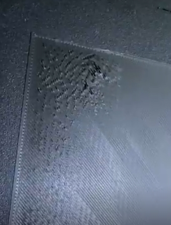
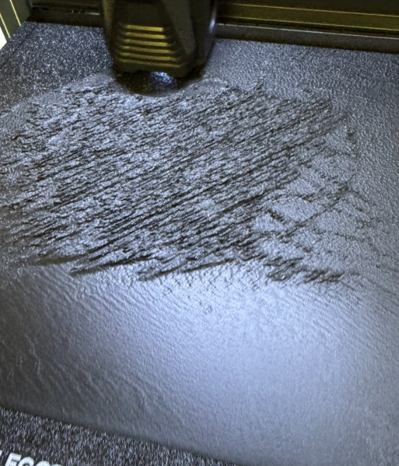
- The first layer does not adhere to the PEI build plate or partially detaches.
- There are obvious gaps between first-layer lines.
- Different areas of the same PEI build plate show inconsistent first-layer printing results.
¶ Possible Causes
- The overall printer structure has not been properly adjusted.
- The proximity switch is malfunctioning or detecting the build plate incorrectly.
- The X-axis parallelism is not calibrated correctly.
- The Z-axis structure is misaligned or operating abnormally.
- The Z Offset value is incorrectly set.
- The PEI build plate is not installed or fitted correctly.
- The heated bed or PEI build plate is warped or deformed.
¶ Required Tools
- 2.0 mm Allen key
- 2.5 mm Allen key
- A4 paper
- Open-end wrench
¶ Troubleshooting Steps
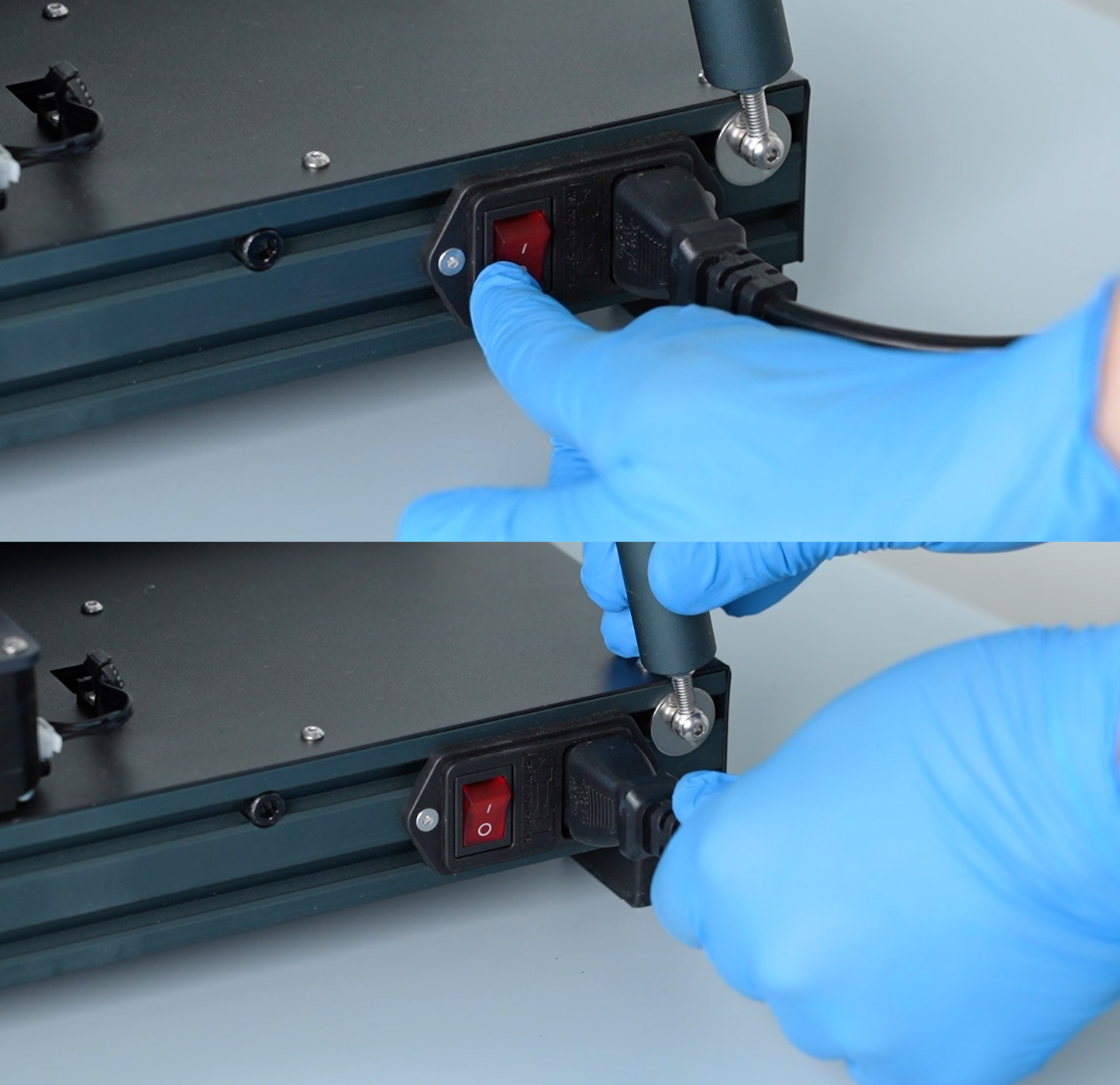
Note: Please turn off the printer power before performing the following inspections and adjustments.
¶ 1. Check the Heated Bed Flatness
- Remove the PEI build plate.
- Check whether the heated bed surface has obvious warping, foreign objects, or other damage.
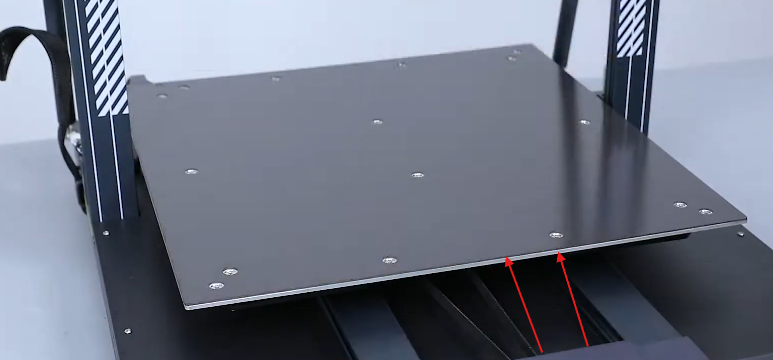
- Confirm that the PEI build plate is fully seated without any local lifting or warping after installation.
¶ 2. Check the PEI Build Plate
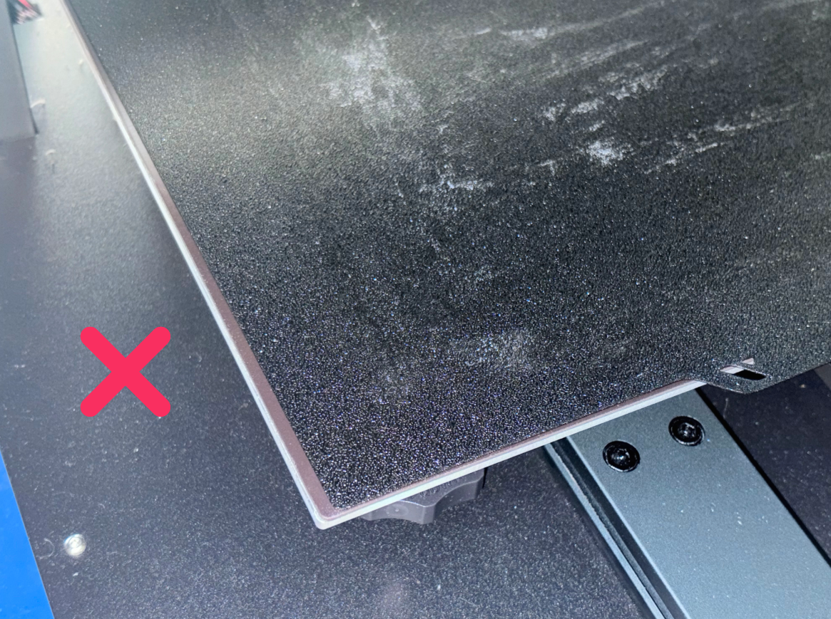
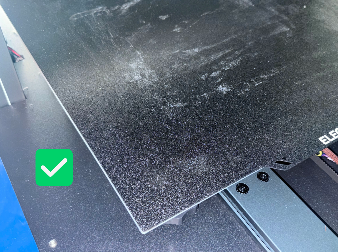
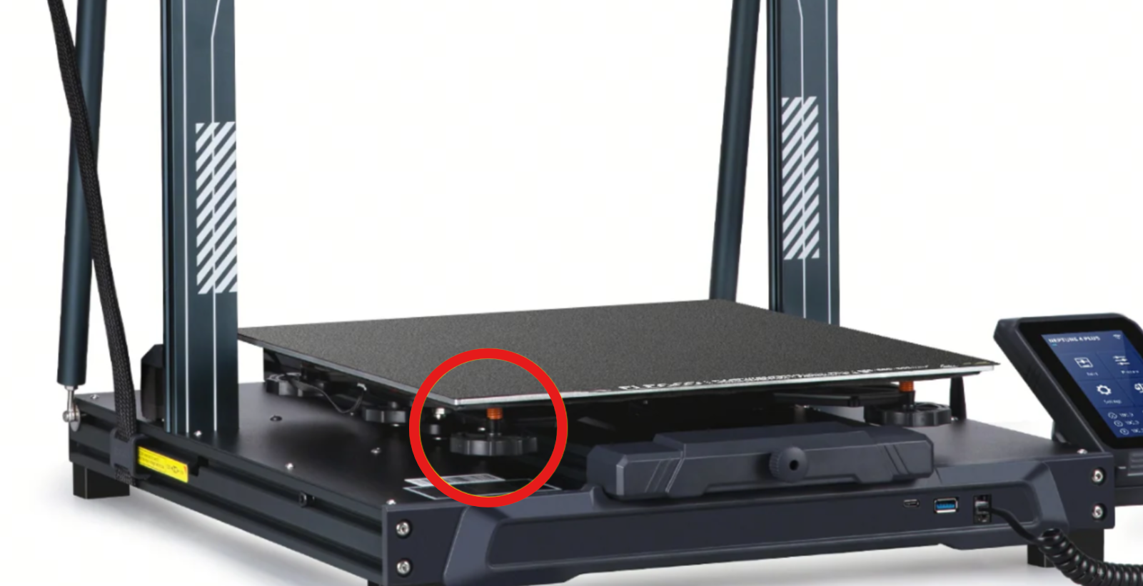
- Please install and fit the PEI build plate correctly according to the figure below. Otherwise, the proximity switch may not correctly detect the build surface height, resulting in poor first-layer printing quality.
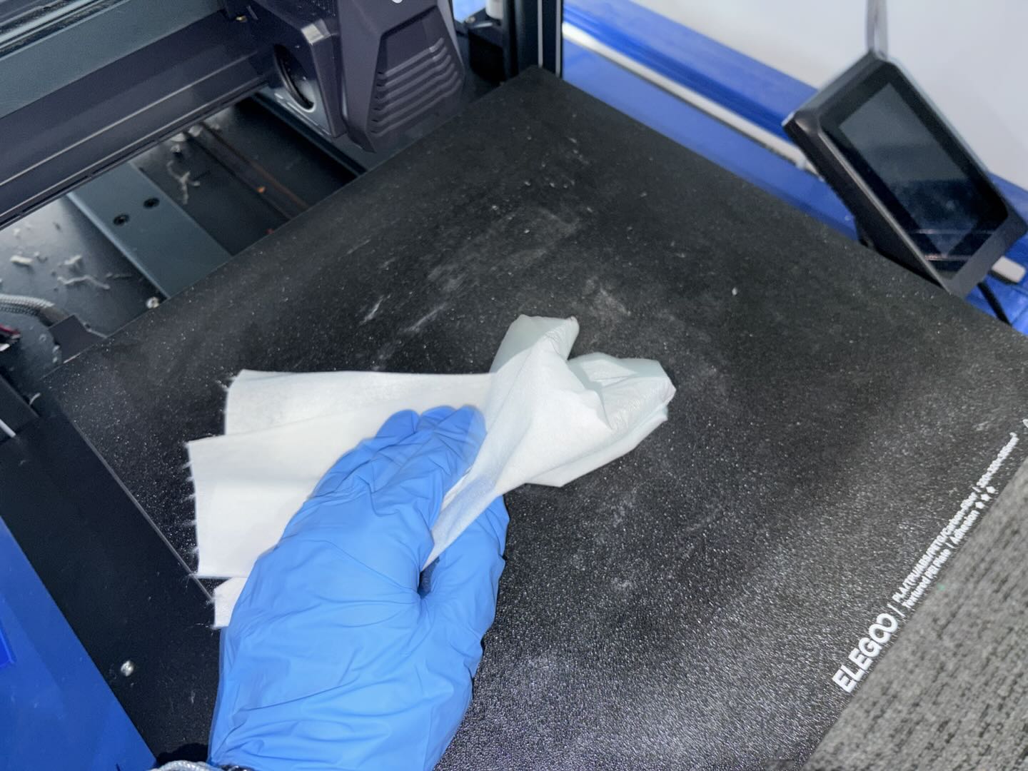
- It is also recommended to clean the PEI build plate to prevent surface oil or contamination from affecting adhesion.
- Use a lint-free cloth or tissue with IPA (isopropyl alcohol, recommended alcohol concentration above 75%) to wipe the surface.
- If there is heavy oil contamination, clean the surface with warm water and a small amount of mild detergent, then dry it completely.
- After cleaning, avoid touching the printing surface directly with your hands.
¶ 3. Check the Overall Printer Structure
- Check whether the heated bed or tool head carriage has excessive play or abnormal resistance during movement. If abnormal, adjust the corresponding POM wheels to ensure smooth movement without noticeable gaps.
Reference video:
https://youtu.be/X-pPs4M_SEw
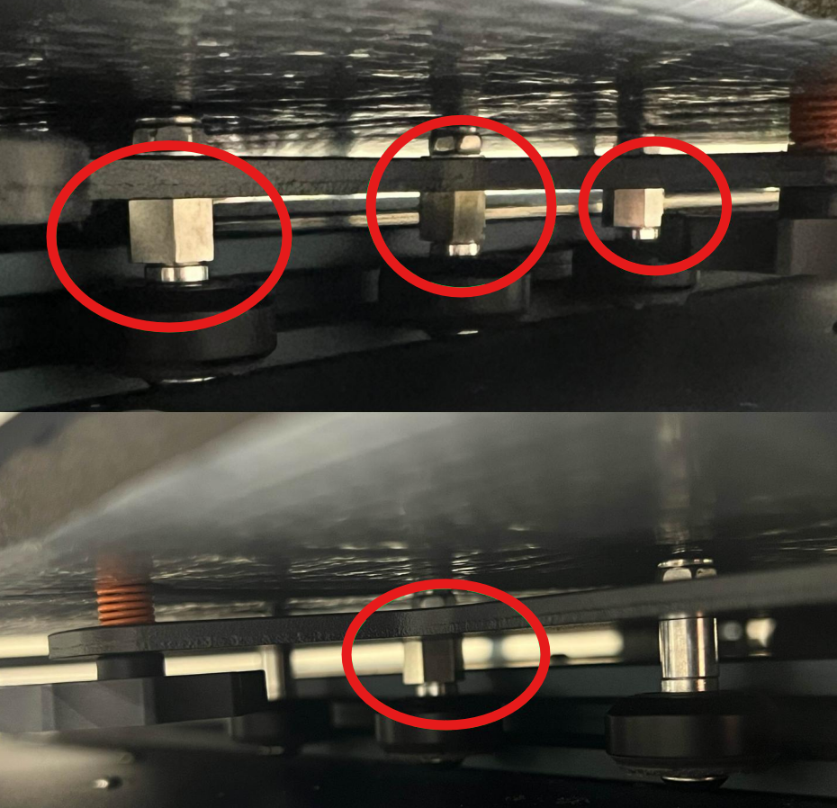
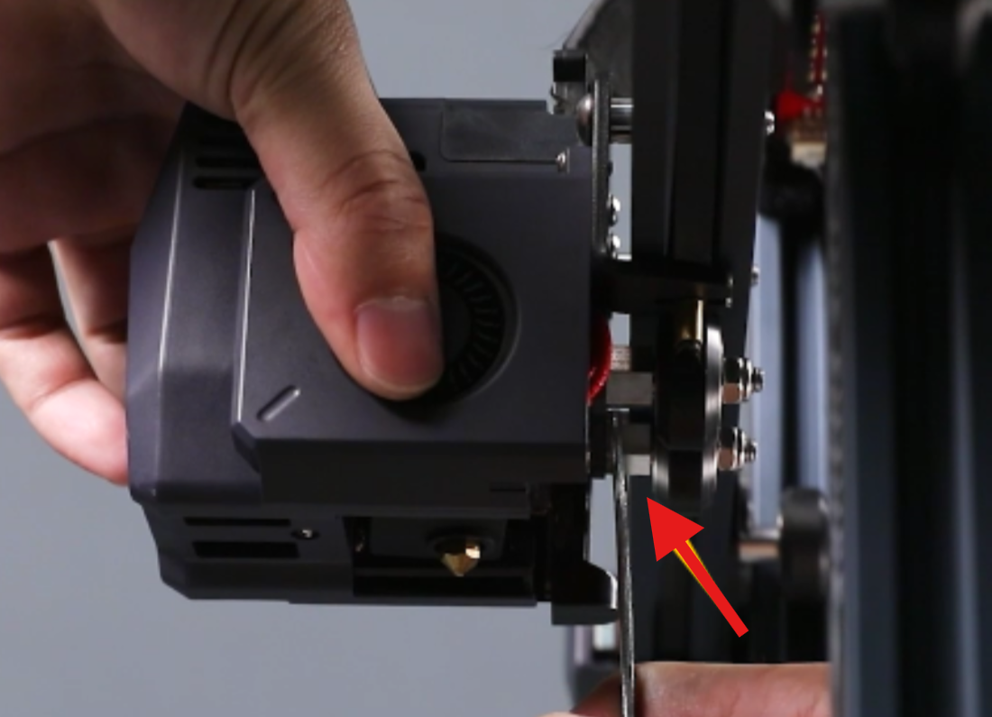
- Ensure that the PEI build plate is flat and firmly attached to the heated bed. Also check whether the heated bed fixing screws are loose.
¶ 4. Check the X-axis Parallelism
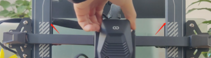
- Move the X-axis close to the top position of the Z-axis lead screws, and check whether the X-axis aluminum extrusion remains parallel with the top of the lead screws.
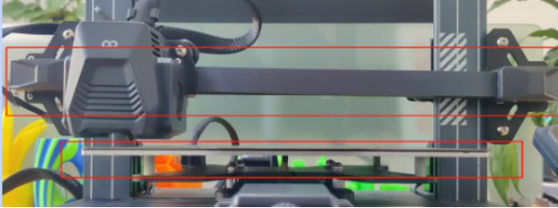
- If it is difficult to confirm visually, use a ruler to measure the distance from both ends of the X-axis to the heated bed and confirm whether both sides have the same height.
- If the X-axis is confirmed to be not parallel, recalibrate the X-axis parallelism.
Note:
The following video is the Neptune 3 Pro X-axis parallelism calibration tutorial. The adjustment method is basically the same for the Neptune 3/4 series. You can refer to the steps shown in the video for adjustment.
https://www.youtube.com/watch?v=lbeevQxRwlI
¶ 5. Check the Proximity Switch
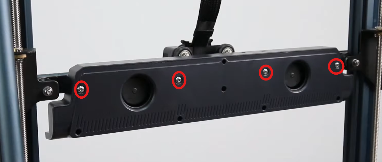
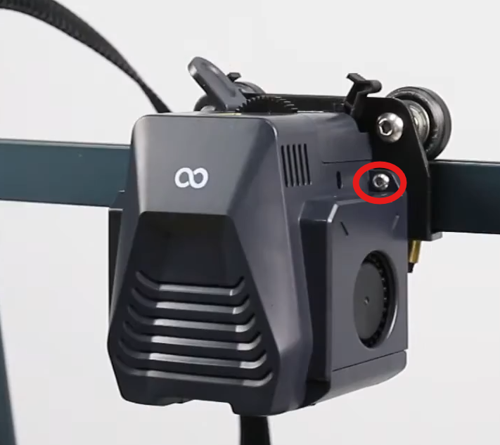
- Use a 2.5 mm Allen key to remove the auxiliary cooling fan assembly.
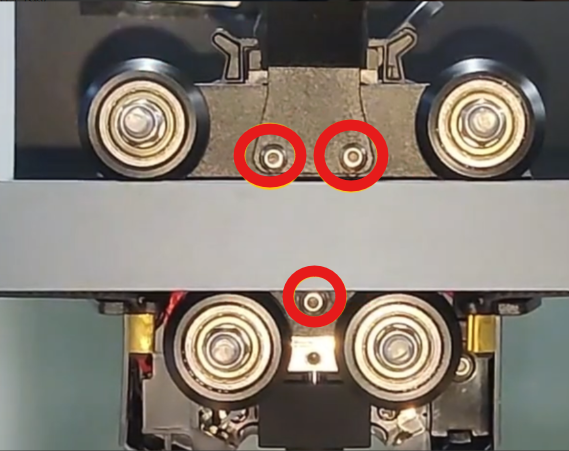
- Use a 2.0 mm Allen key to remove the three screws securing the tool head and rear cover assembly.
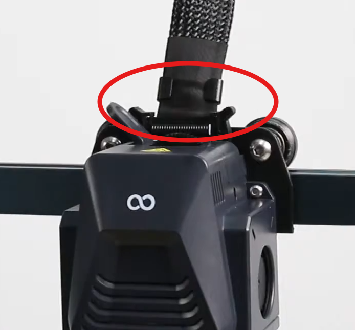
- Remove the ribbon cable assembly.
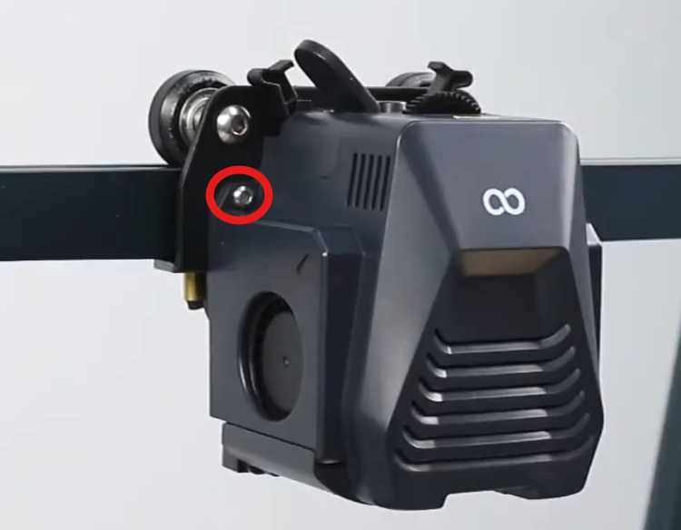
- Use a 2.0 mm Allen key to remove the two screws securing the front cover of the tool head, then remove the tool head.
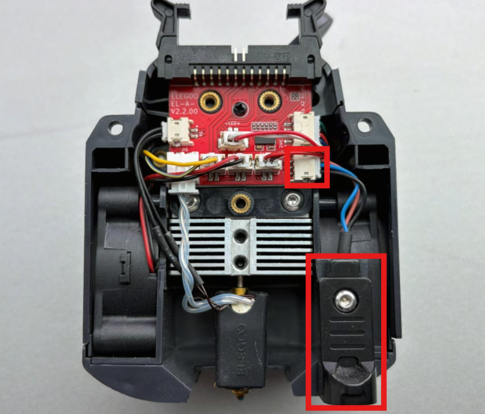
- Check whether the internal proximity switch connection cable is damaged, loose, or not properly secured.
¶ 6. Check the Z-axis Structure
1. Check and Adjust the Z-axis Structure
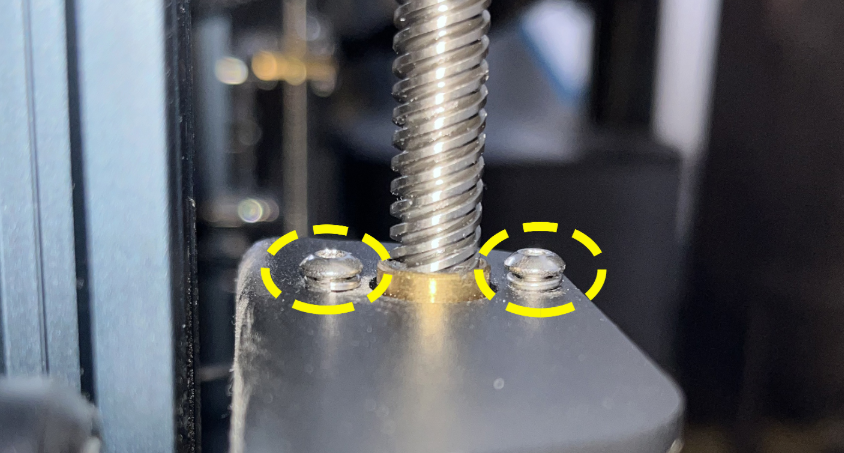
Check and readjust the Z-axis uprights, couplers, and lead screw fixing screws to ensure the Z-axis structure is secure and free of looseness.
Note:
Do not fully tighten these screws. Otherwise, it may increase Z-axis movement resistance and cause the Z-axis to become stuck during upward movement.
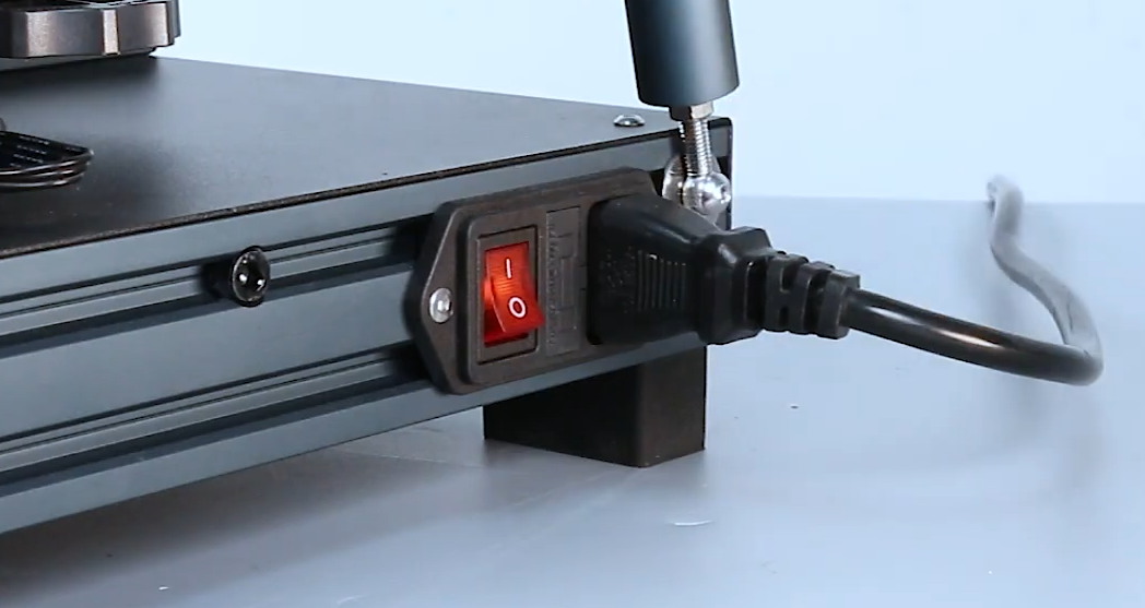
2. Power On the Printer
3. Perform Auto Leveling and Reset the Z Offset
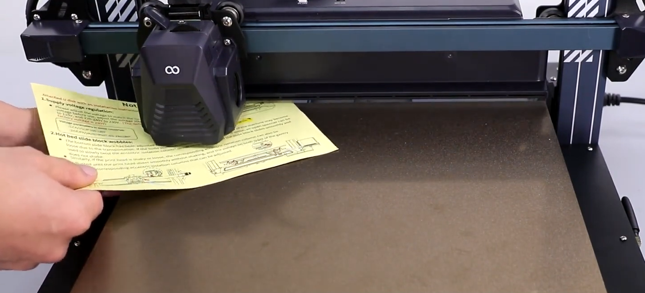
Perform auto leveling and reset the Z Offset value. Use A4 paper to assist in adjusting the distance between the nozzle and the PEI build plate.
Reference video: Start from 7:35 for the leveling operation.
4. Fine-tune the Z Offset Value
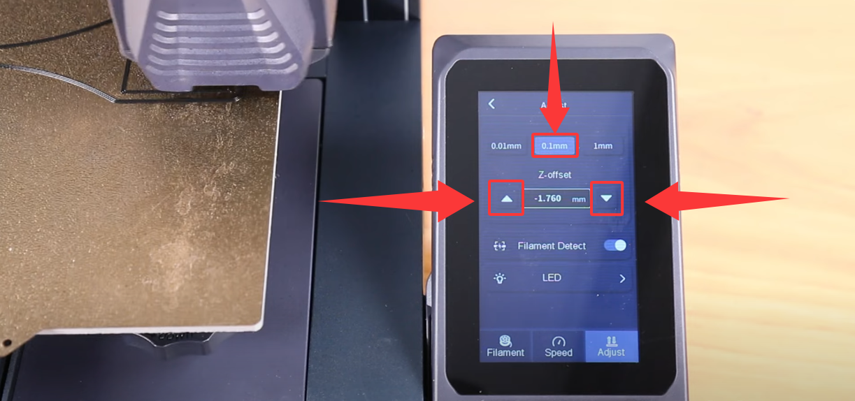
- If the nozzle is too far from the PEI build plate, causing the first-layer lines to not be pressed properly or leaving obvious gaps, decrease the Z Offset value (make it more negative) to move the nozzle closer to the PEI build plate.
- If the nozzle is too close to the PEI build plate, causing excessive first-layer compression or preventing normal extrusion, increase the Z Offset value to move the nozzle farther away from the PEI build plate.
Please refer to the following video:
¶ Issue Not Resolved
If the first-layer printing quality still cannot be improved after following the above steps, please provide the following information and contact our technical support team at 3dp@elegoo.com for further assistance.
-
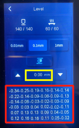
Provide a photo of the machine leveling point parameters:
-
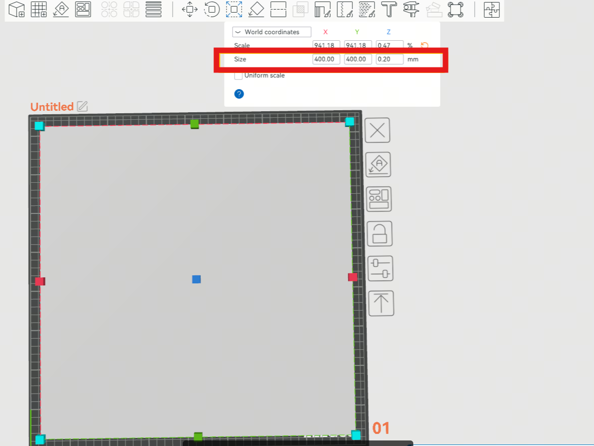
Provide a photo of the first-layer print result.
Create a 400 × 400 × 0.2 mm cube and print the first layer.
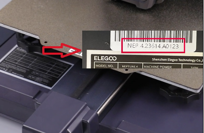
- Provide the machine SN code.
SN code format: NEP X.XXXXX.XXXXX
¶ Help us improve
If you have any ideas about the wiki pages, please let us know via ELEGOO official feedback channel