¶ Preparation
Turn off the printer using the Switch and unplug the power cable from the DC Socket.
Remove the Anti-UV Cover, Build Plate, and Resin Tray.
¶ Required Tools
- 2.0 mm hex screwdriver
- 2.5 mm hex screwdriver
- 3.0 mm hex screwdriver
- Cutting pliers
- Ethyl Alcohol
¶ Disassembly Steps
¶ Remove Rear Panel
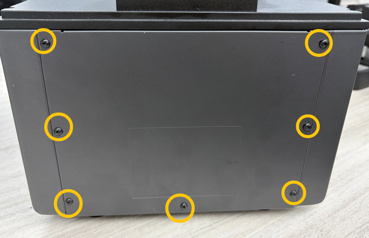
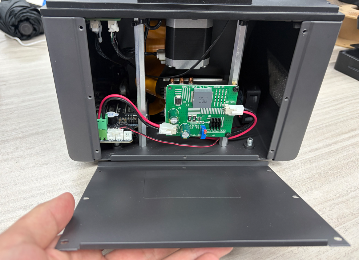
Use a 2.0 mm hex screwdriver to remove the seven screws securing the rear panel, then remove the rear panel.
¶ Remove Left Panel
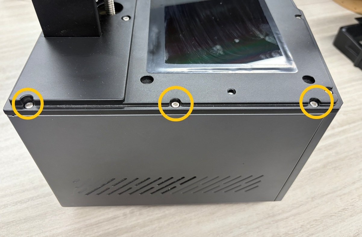
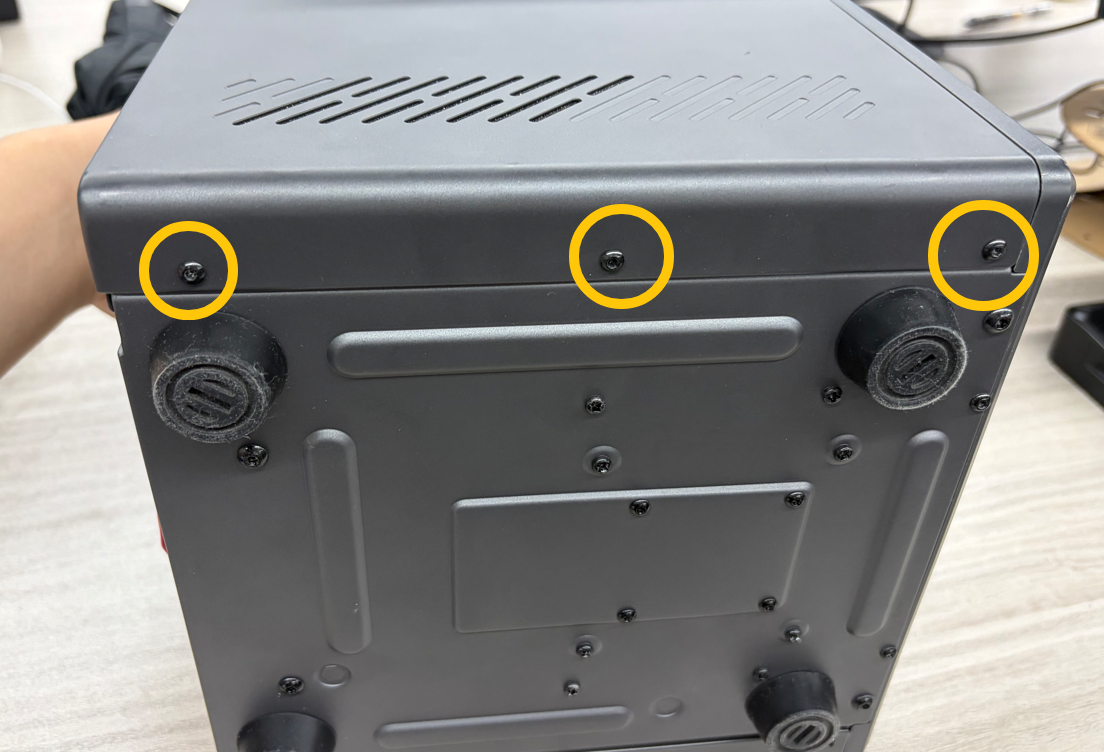
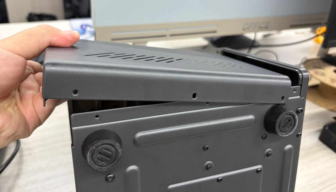
Use a 2.5 mm hex screwdriver to remove the three upper screws securing the left panel.
Use a 2.0 mm hex screwdriver to remove the three lower screws securing the left panel, then remove the left panel.
¶ Remove Front Panel
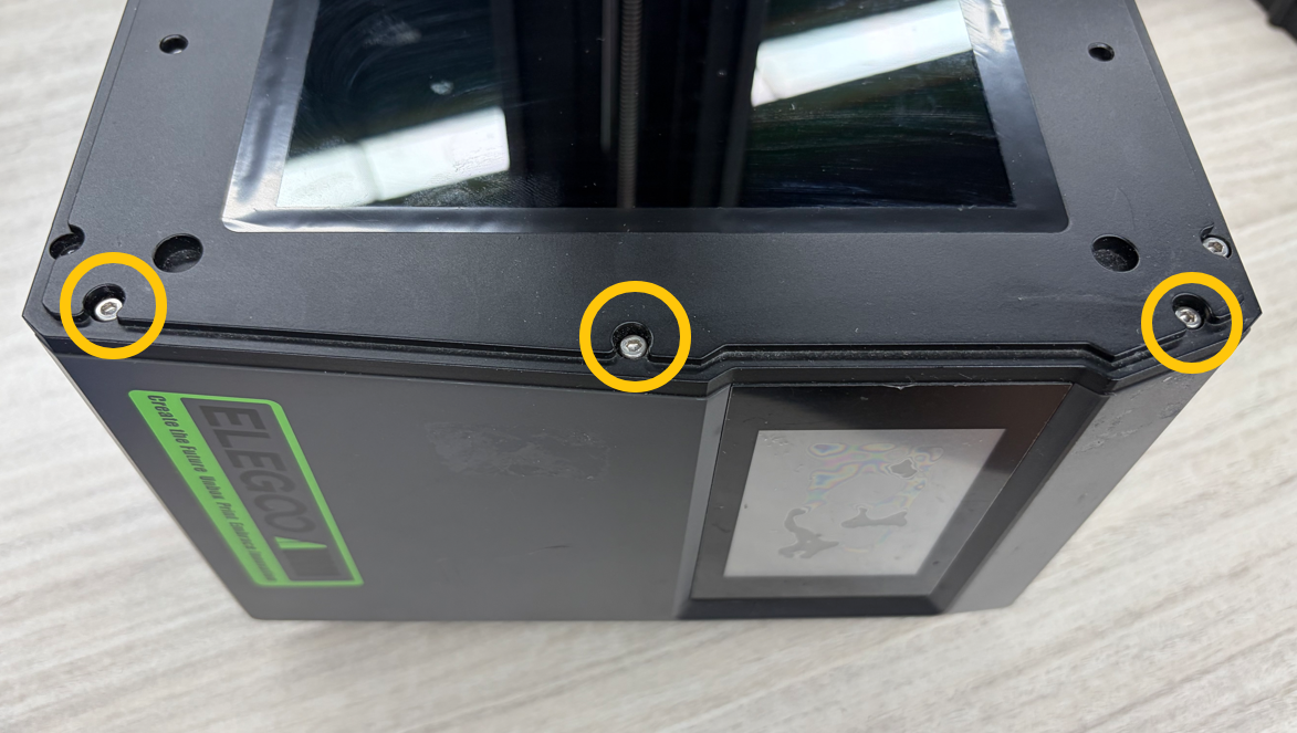
Use a 2.5 mm hex screwdriver to remove the three upper screws securing the front panel.
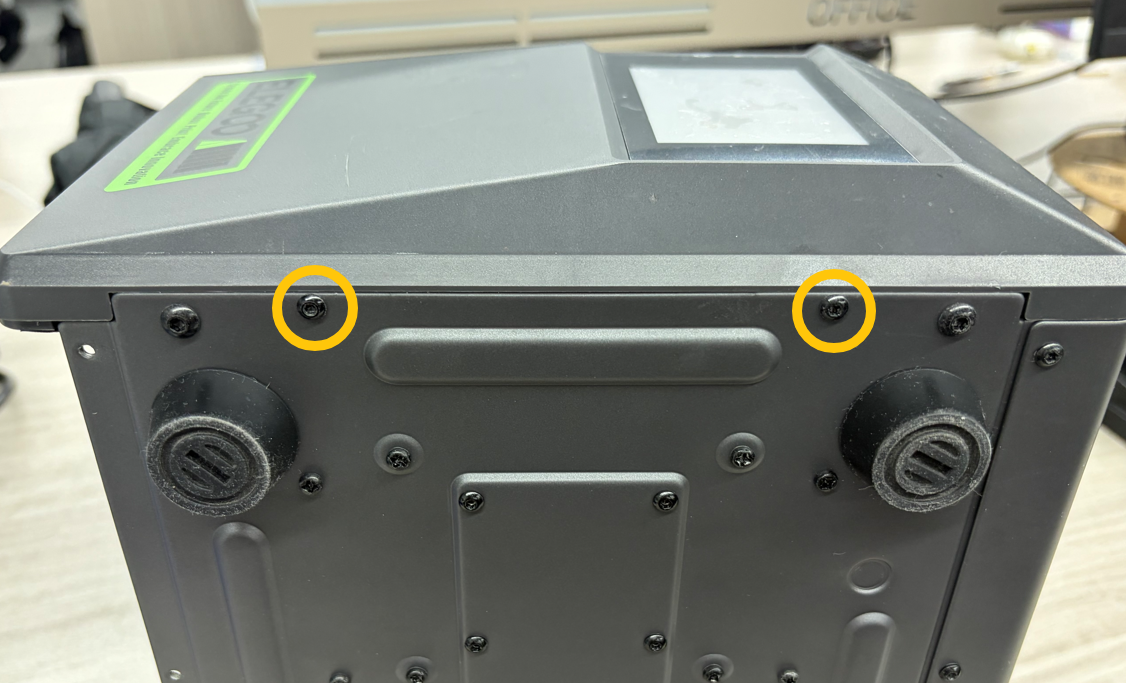
Use a 2.0 mm hex screwdriver to remove the two lower screws securing the front panel.
Slowly lift the front panel.
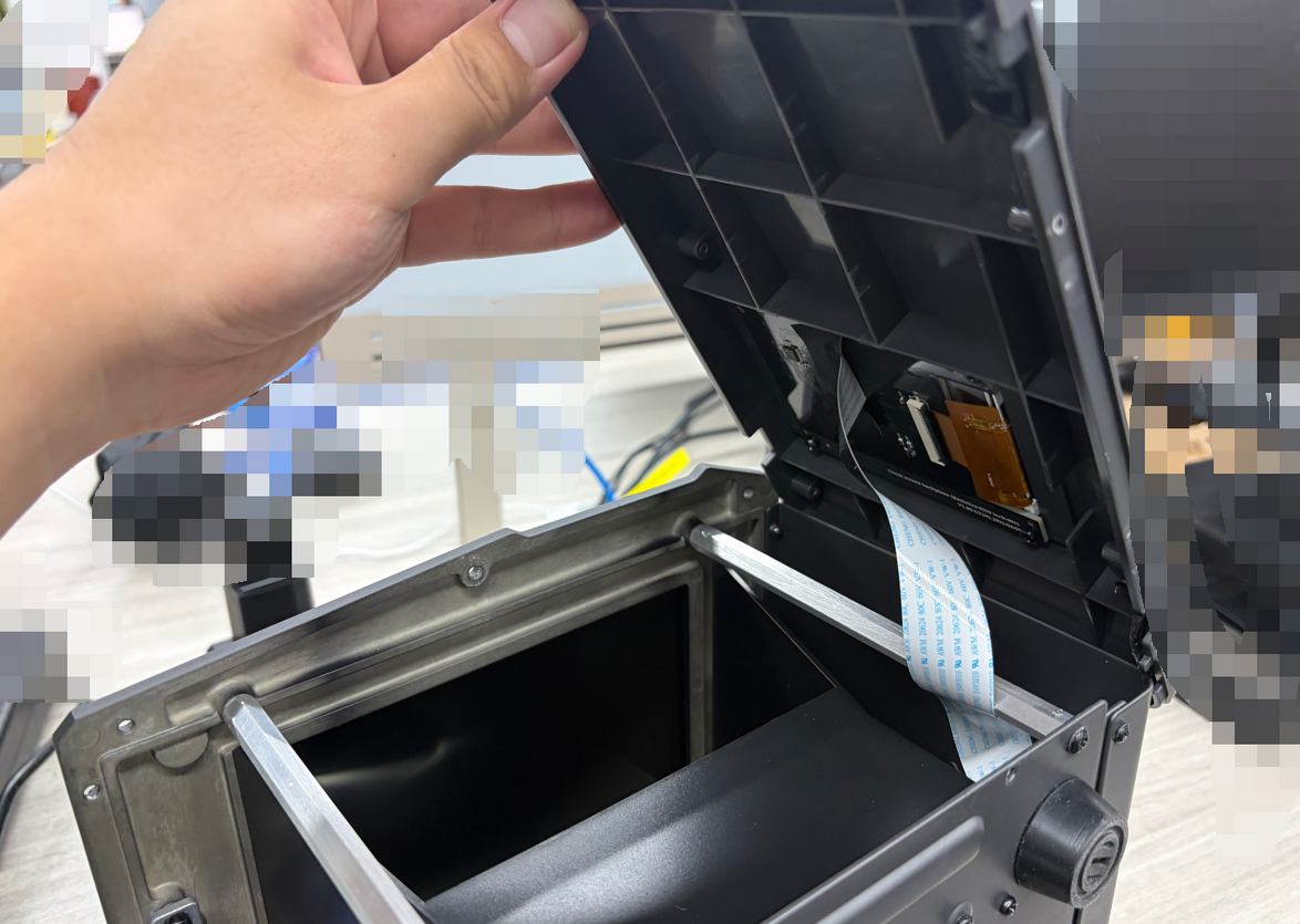
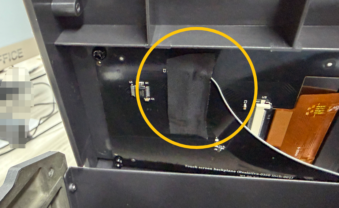
Remove the tape securing the Touch Screen cable, unlock the latch, disconnect the Touch Screen cable, and remove the front panel.
¶ Remove Right Panel
Use a 2.5 mm hex screwdriver to remove the three upper screws securing the right panel.
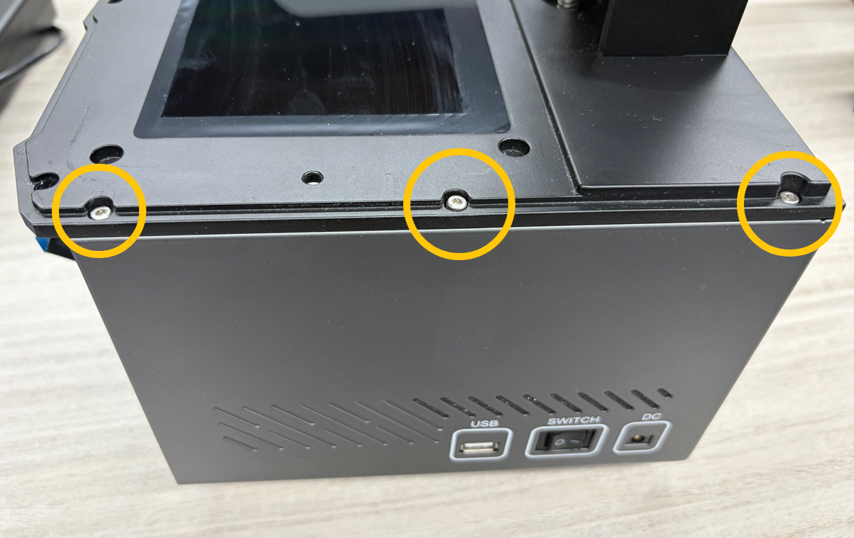
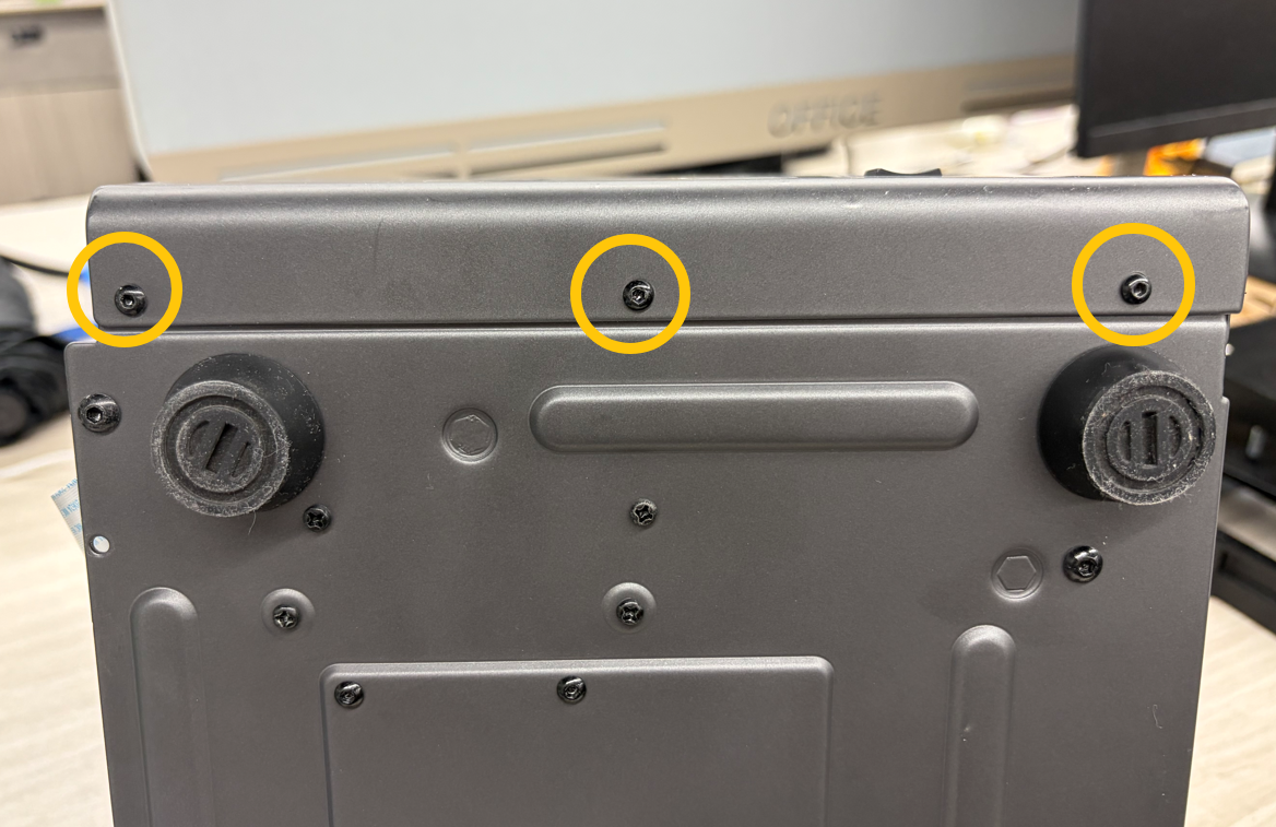
Use a 2.0 mm hex screwdriver to remove the three lower screws, then remove the right panel.
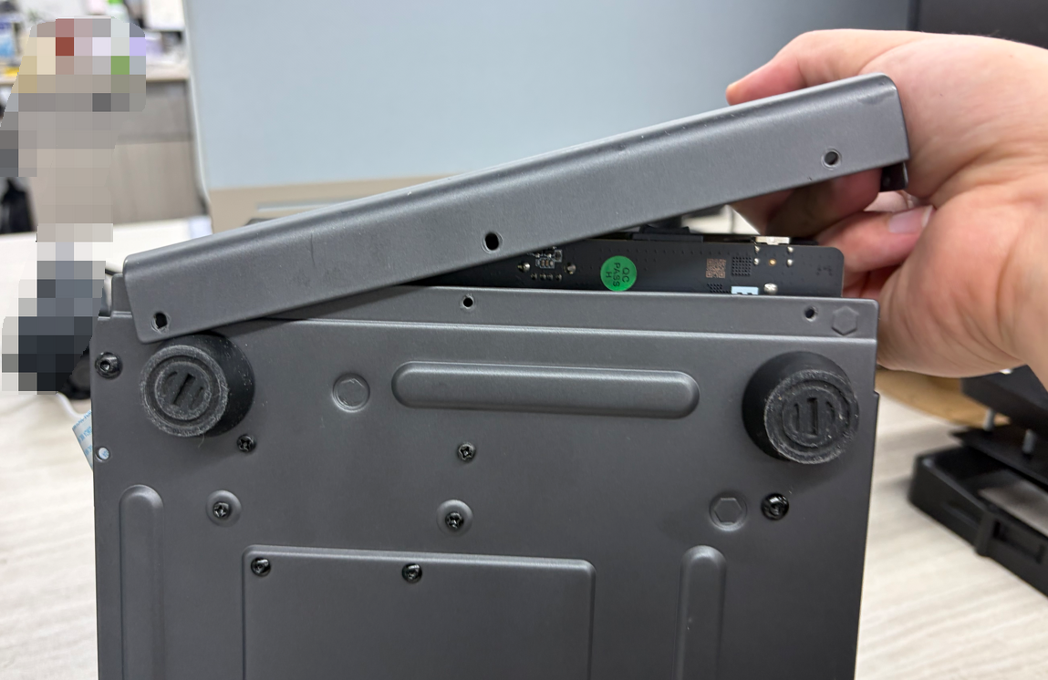
¶ Disconnect Mainboard Cables
Disconnect all cables on the mainboard except the Touch Screen cable.
Note: If the hot melt adhesive on the connectors is difficult to remove, apply a small amount of Ethyl Alcohol to the adhesive area. Wait 2–3 minutes for it to soften before removal.
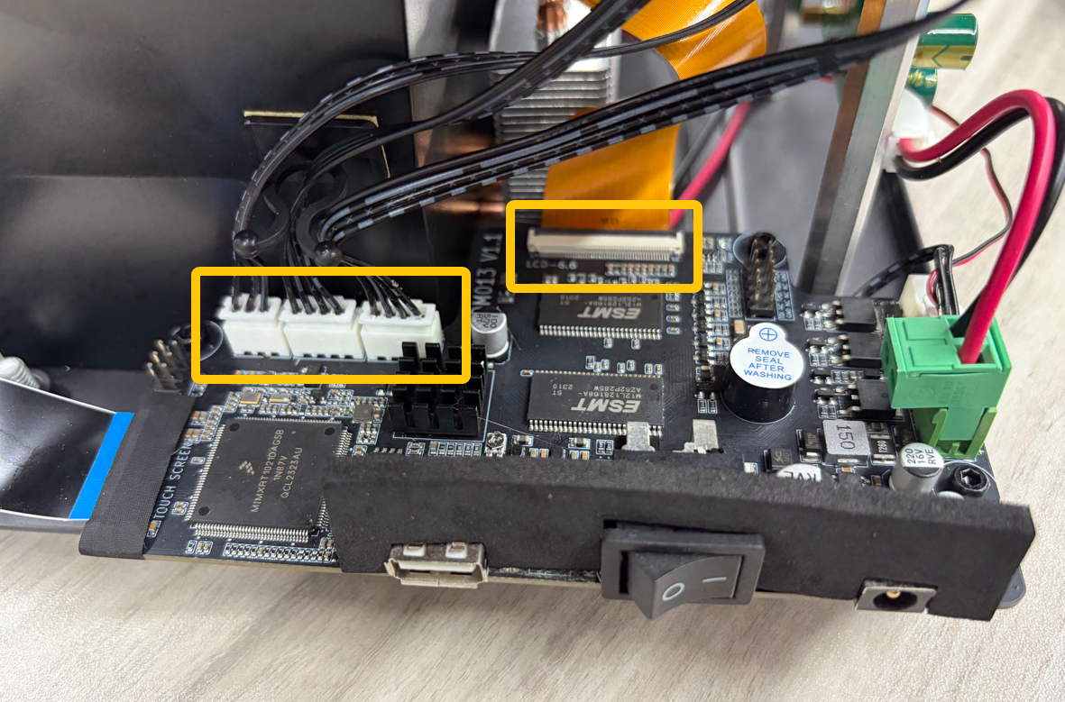
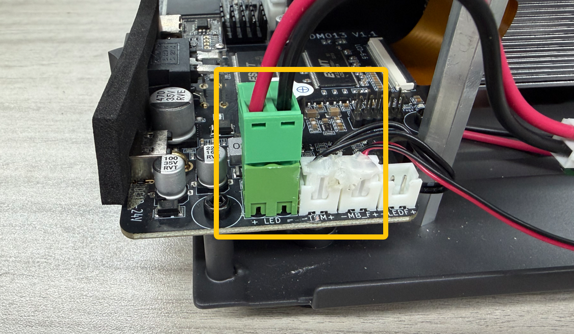
Disconnect the left-side connector of the Constant Current Board.
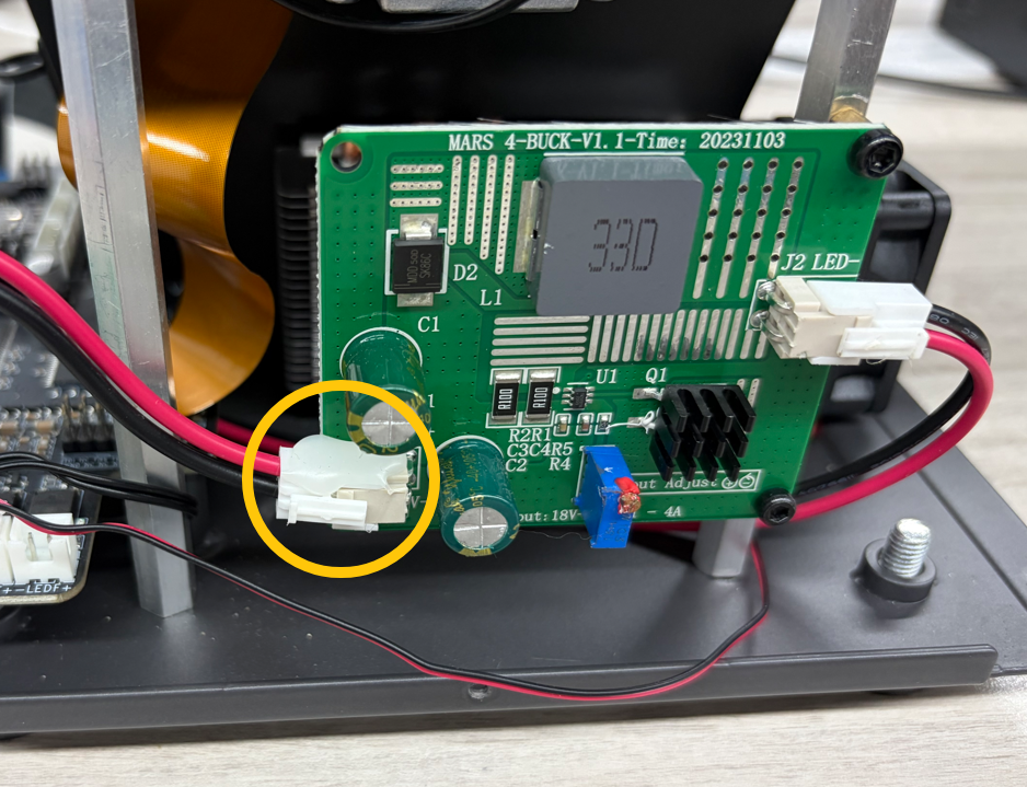
¶ Remove Base
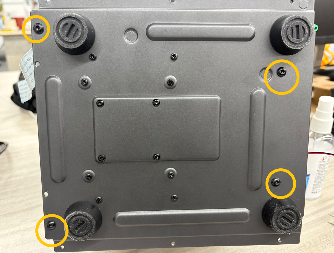
Use a 2.5 mm hex screwdriver to remove the four screws securing the base.
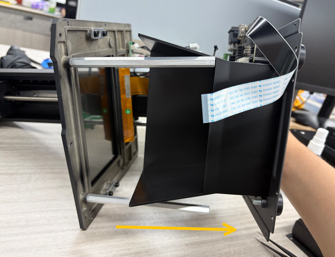
Slide the base out from the right side.
¶ Remove Z Cover Plate
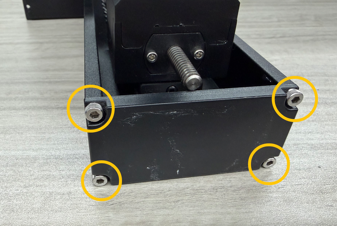
Use a 3.0 mm hex screwdriver to remove the four screws securing the Z Axis cover plate, then remove the cover.
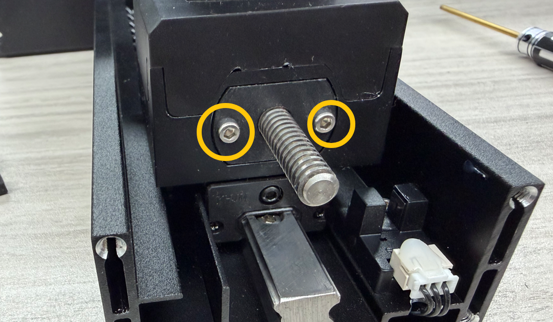
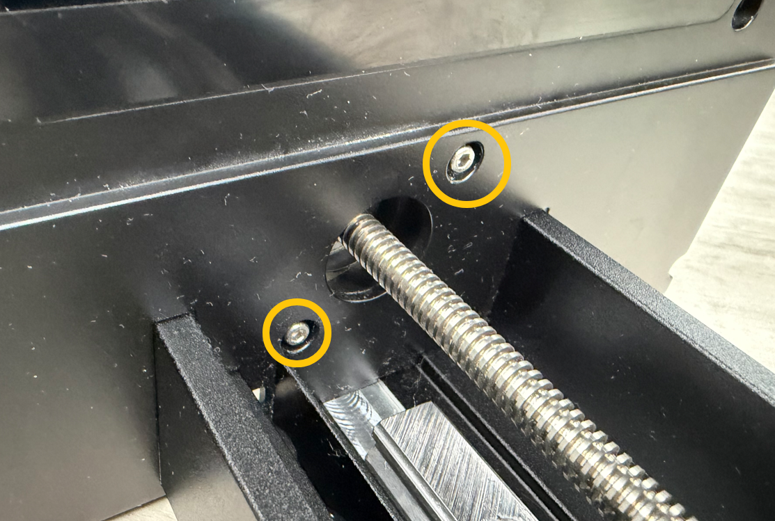
Use a 2.5 mm hex screwdriver to remove the two screws securing the Anti-backlash Nut.
¶ Remove Anti-backlash Nut
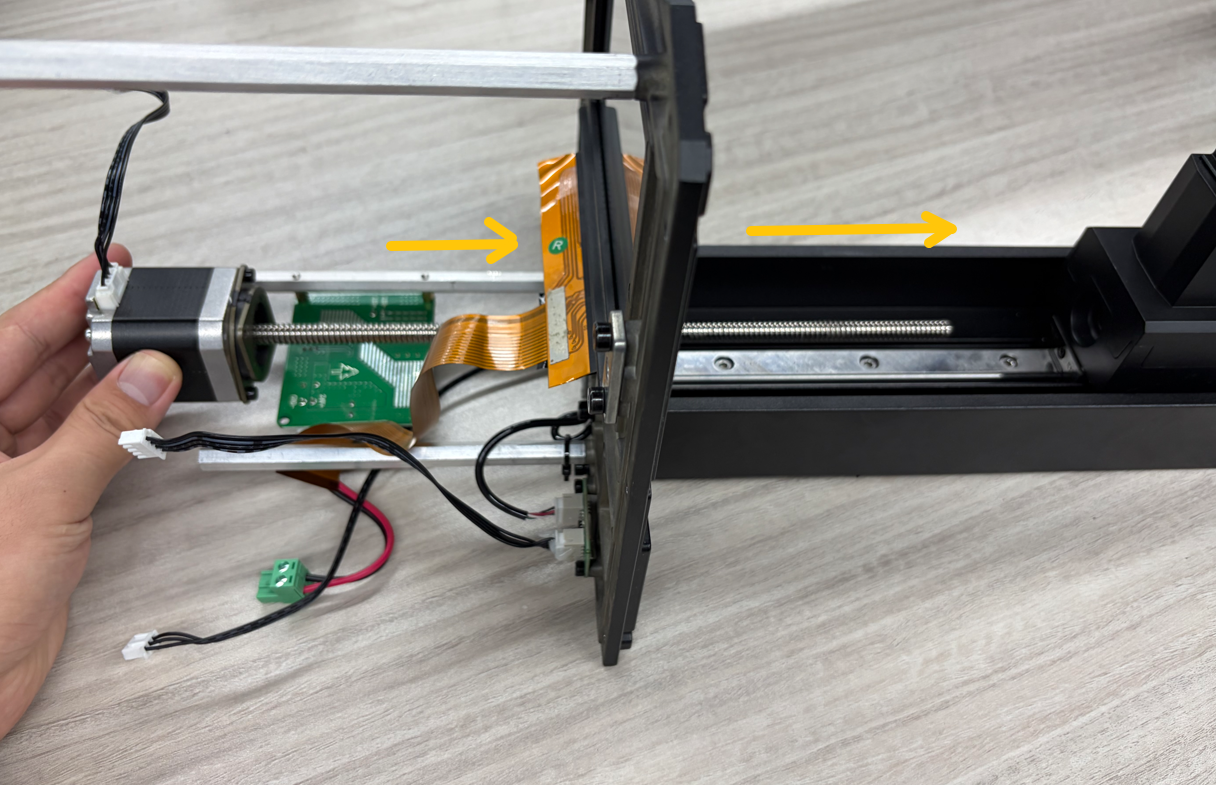
Push the gantry arm forward.
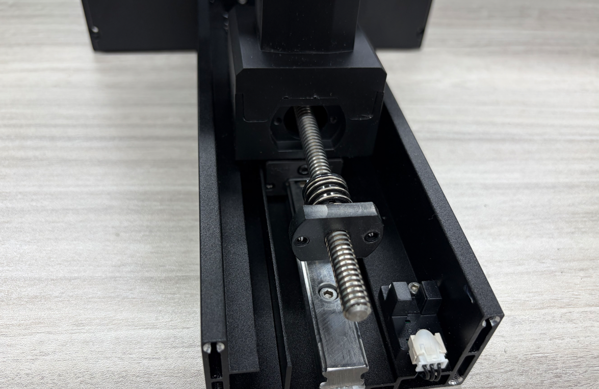
Support the Lead Screw, then manually rotate the Anti-backlash Nut until it is removed.
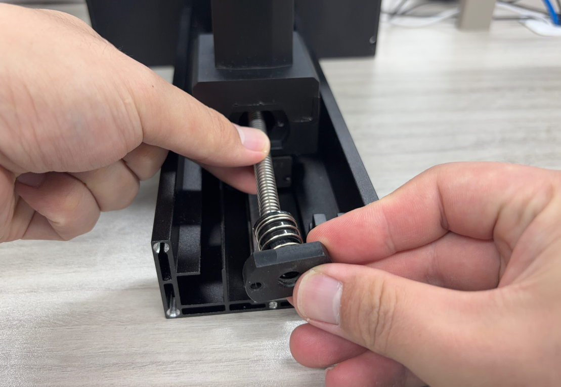
¶ Remove Z Axis Motor
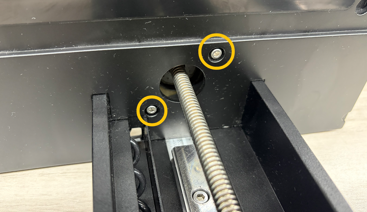
Use a 2.5 mm hex screwdriver to remove the two screws securing the Z Axis motor.
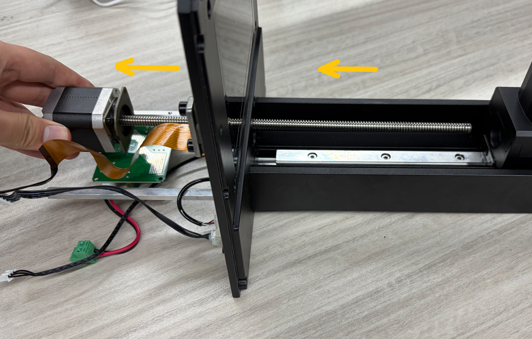
Remove the Z Axis motor from the left side.
¶ Installation Steps
¶ Install Z Axis Motor
Take out the new Z Axis motor.
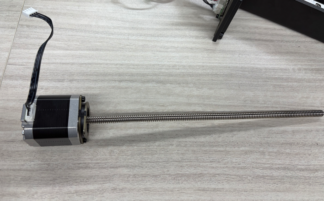
Install the Z Axis motor into the left side of the middle frame.
Tighten the two screws securing the Z Axis motor.
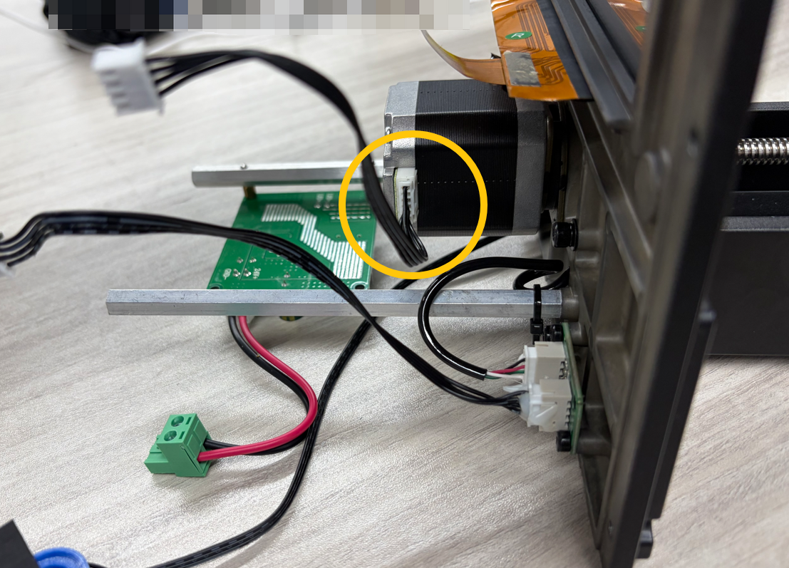
Note: The motor connector must face toward the right panel of the printer.
¶ Install Anti-backlash Nut
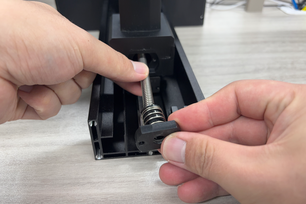
Hold the Lead Screw and thread the Anti-backlash Nut onto the Lead Screw.
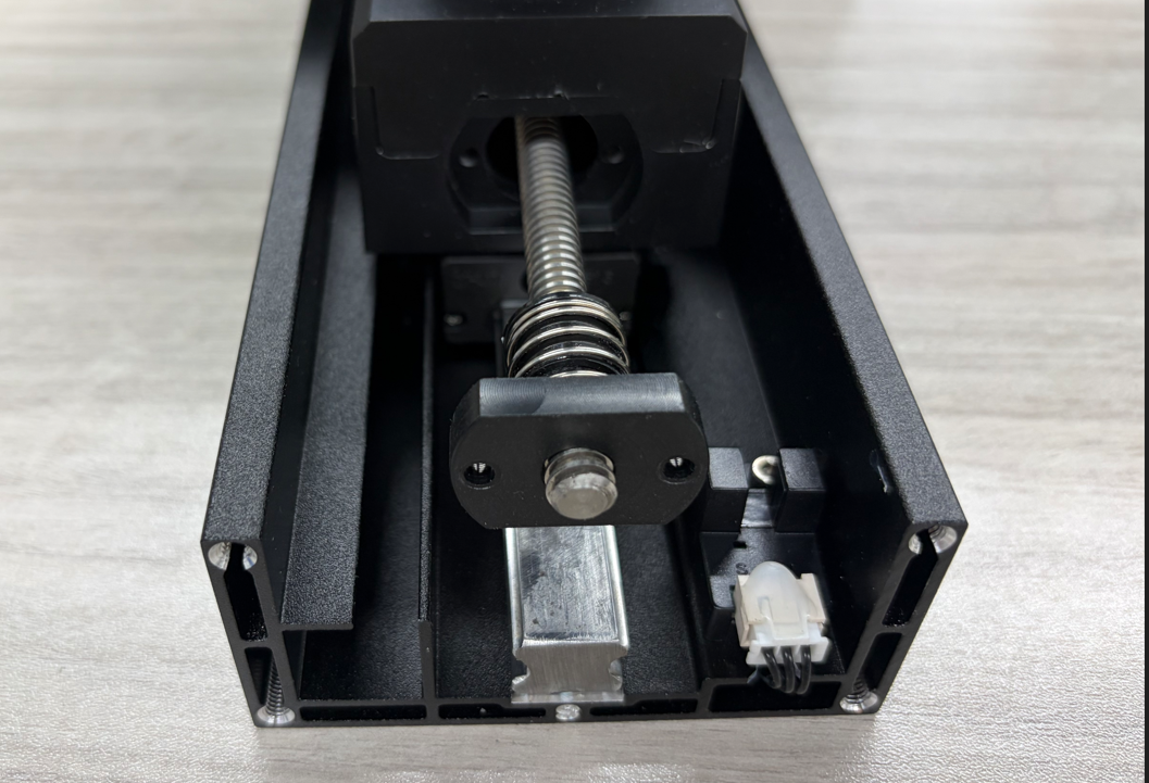
Push the gantry arm downward.}
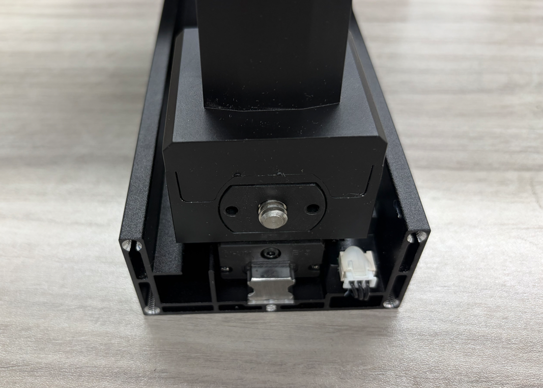
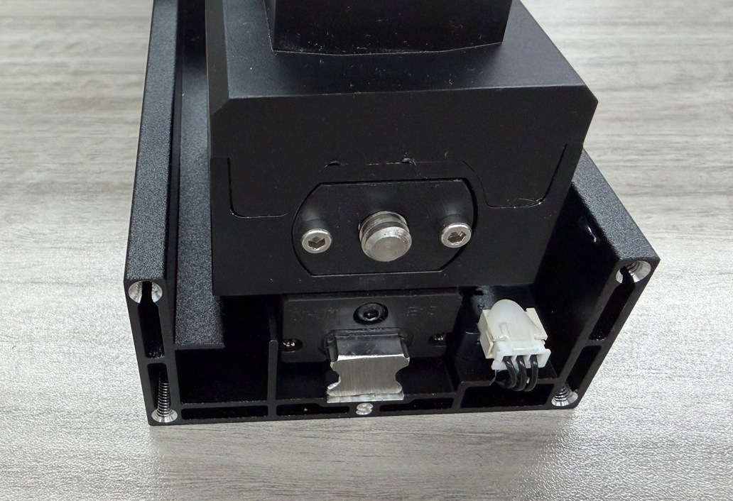
Tighten the two screws securing the Anti-backlash Nut.
¶ Install Z Cover Plate
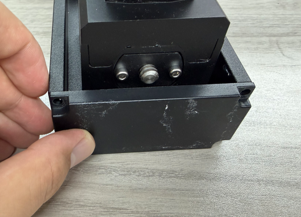
Place the Z Axis cover plate back into position.
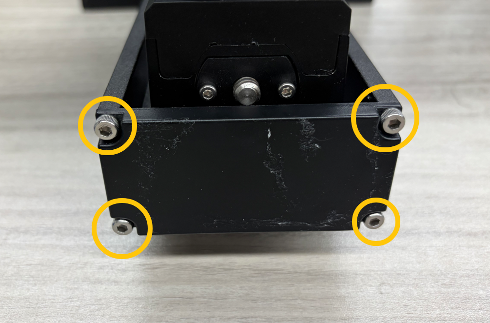
Tighten the four screws securing the Z Axis cover plate.
¶ Install Base
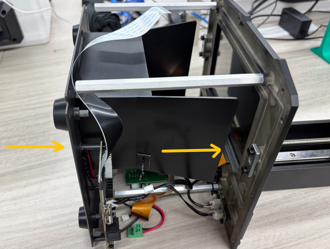
Slide the base into position from the left side.
 }
}
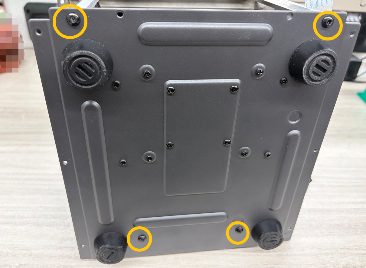
Tighten the four screws securing the base.
¶ Reconnect Mainboard Cables
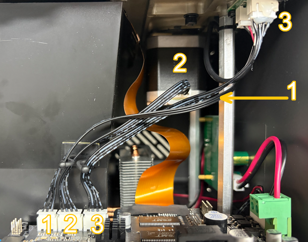
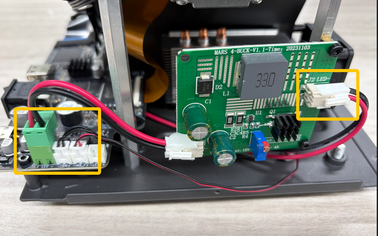
Reconnect the mainboard and Constant Current Board cables to their original positions.
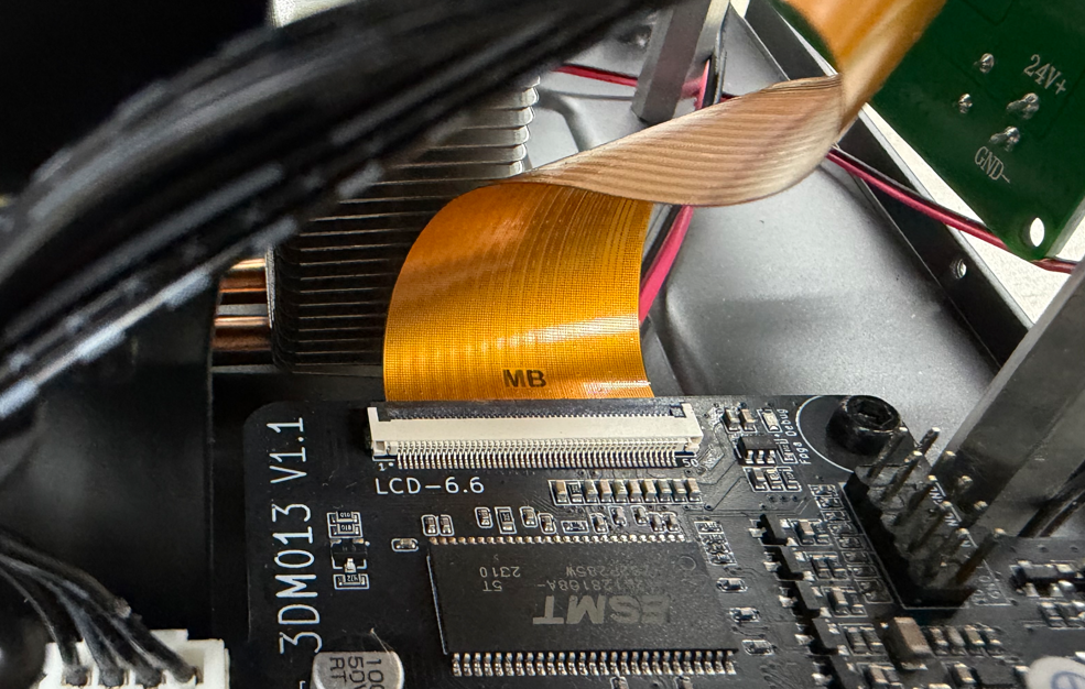
Note: The side of the LCD cable marked with “MB” must face upward. Ensure the LCD cable is fully inserted and not tilted; otherwise, the LCD Display Screen may not display correctly.
¶ Install Front Panel
Place the front panel on a work surface temporarily.
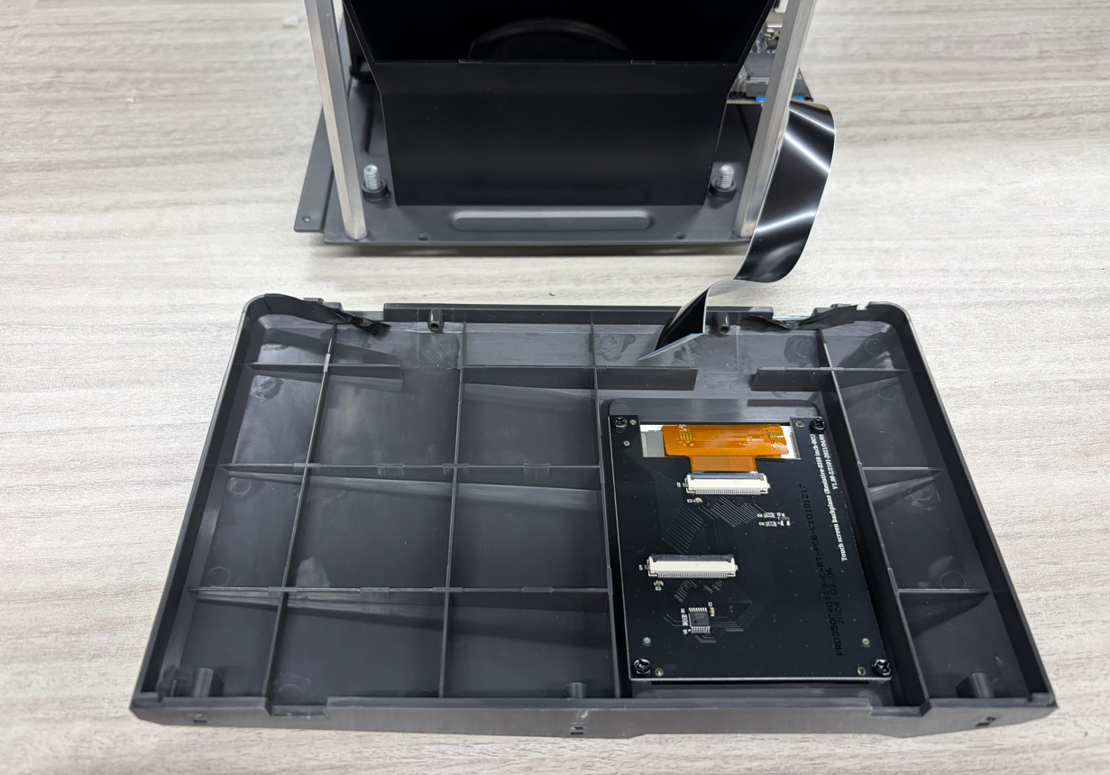
Insert the Touch Screen cable into the Touch Screen rear port, lock the latch, and secure it with Mylar Tape.
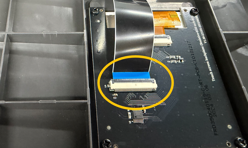
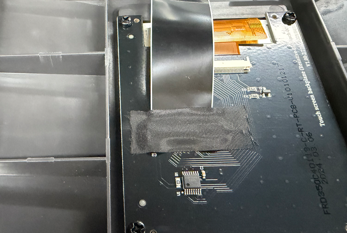
Place the front panel back into position.
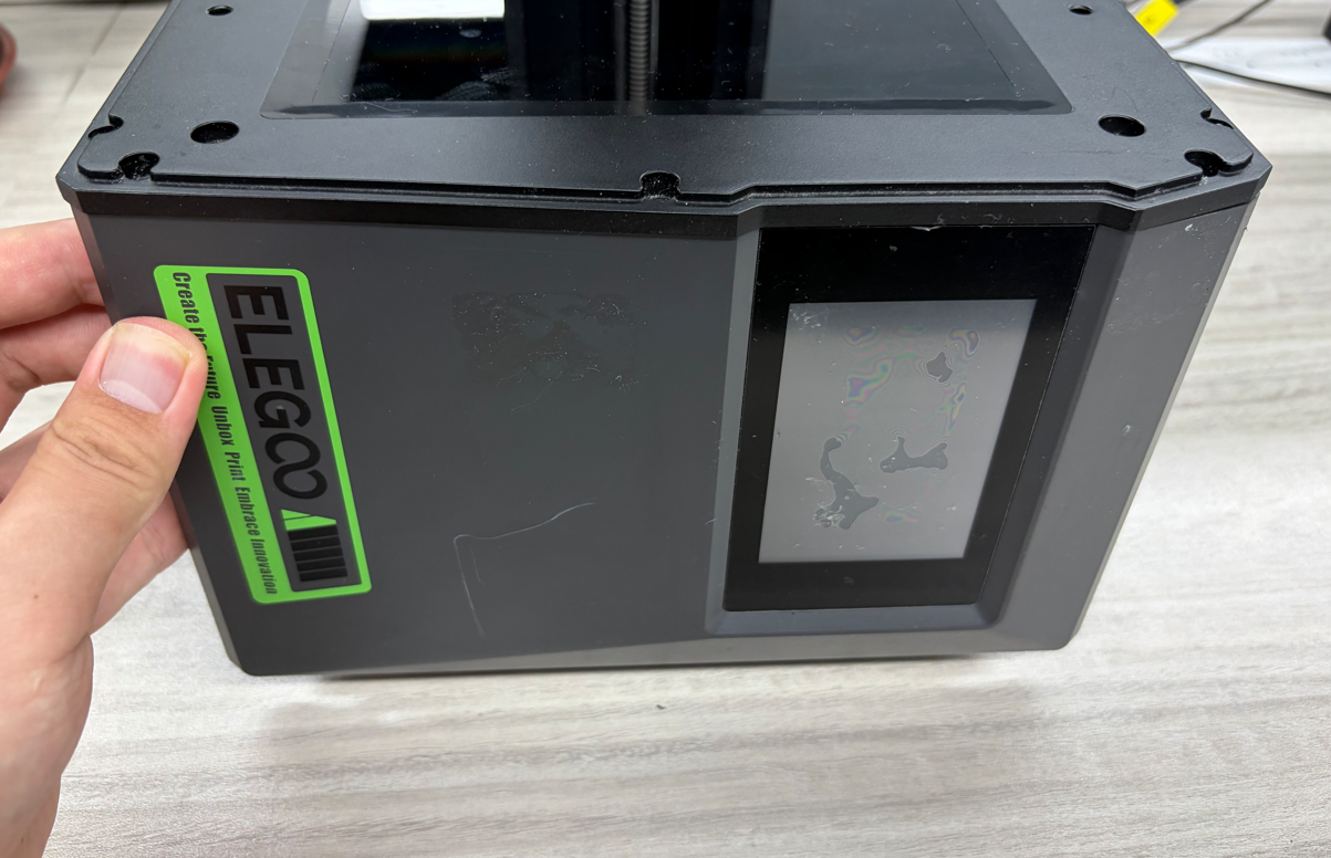
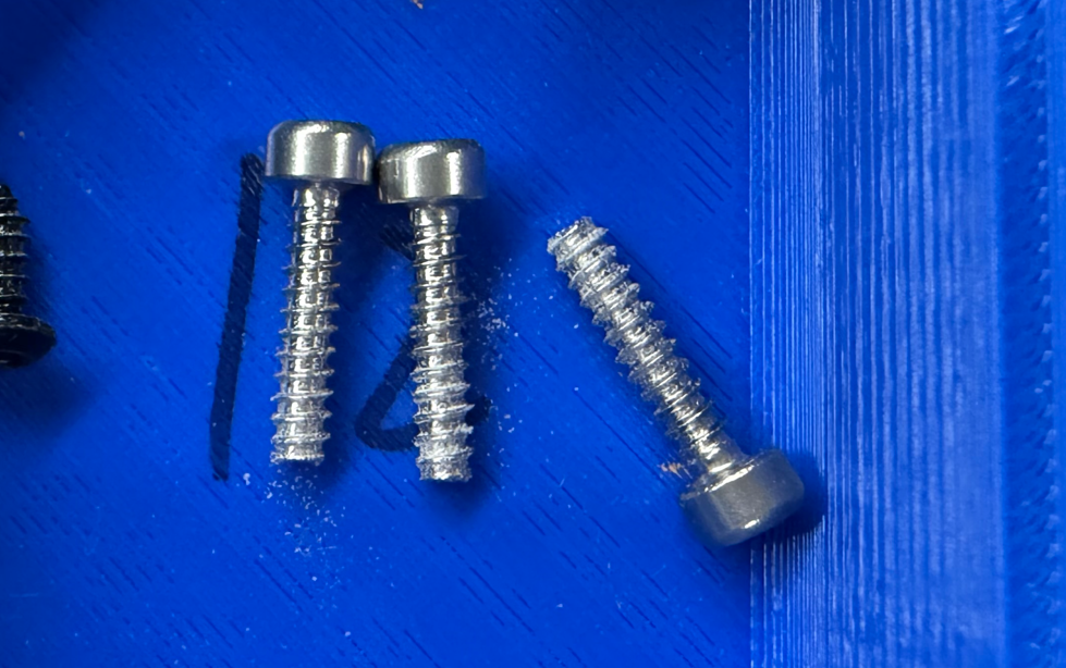
Tighten the three upper screws securing the front panel.
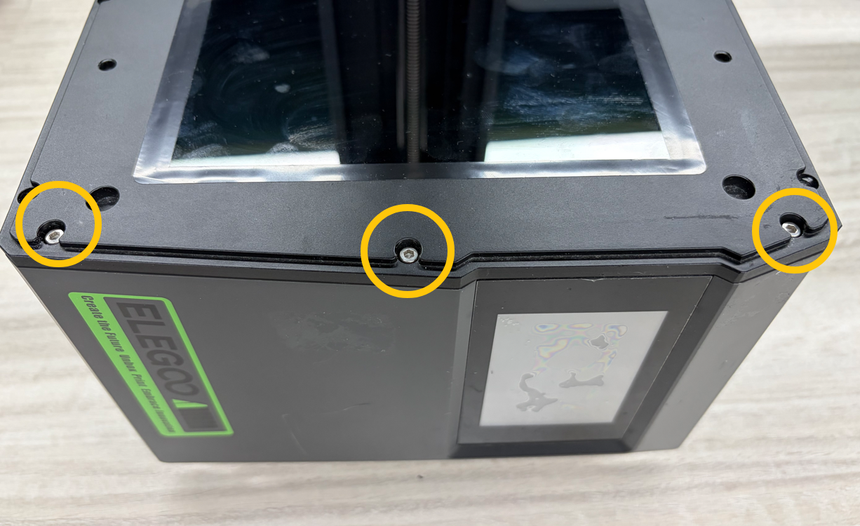
Note: The upper screws are self-tapping screws.{.is-info}
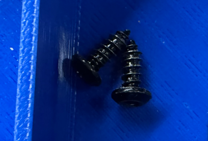
Tighten the two lower screws securing the front panel.
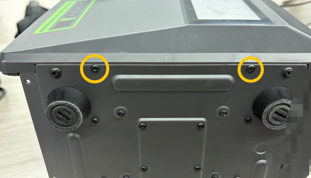
Note: The lower screws are self-tapping screws.
¶ Install Left Panel
Place the left panel back into position.
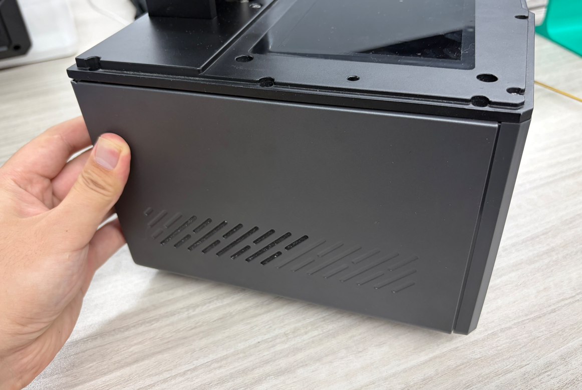
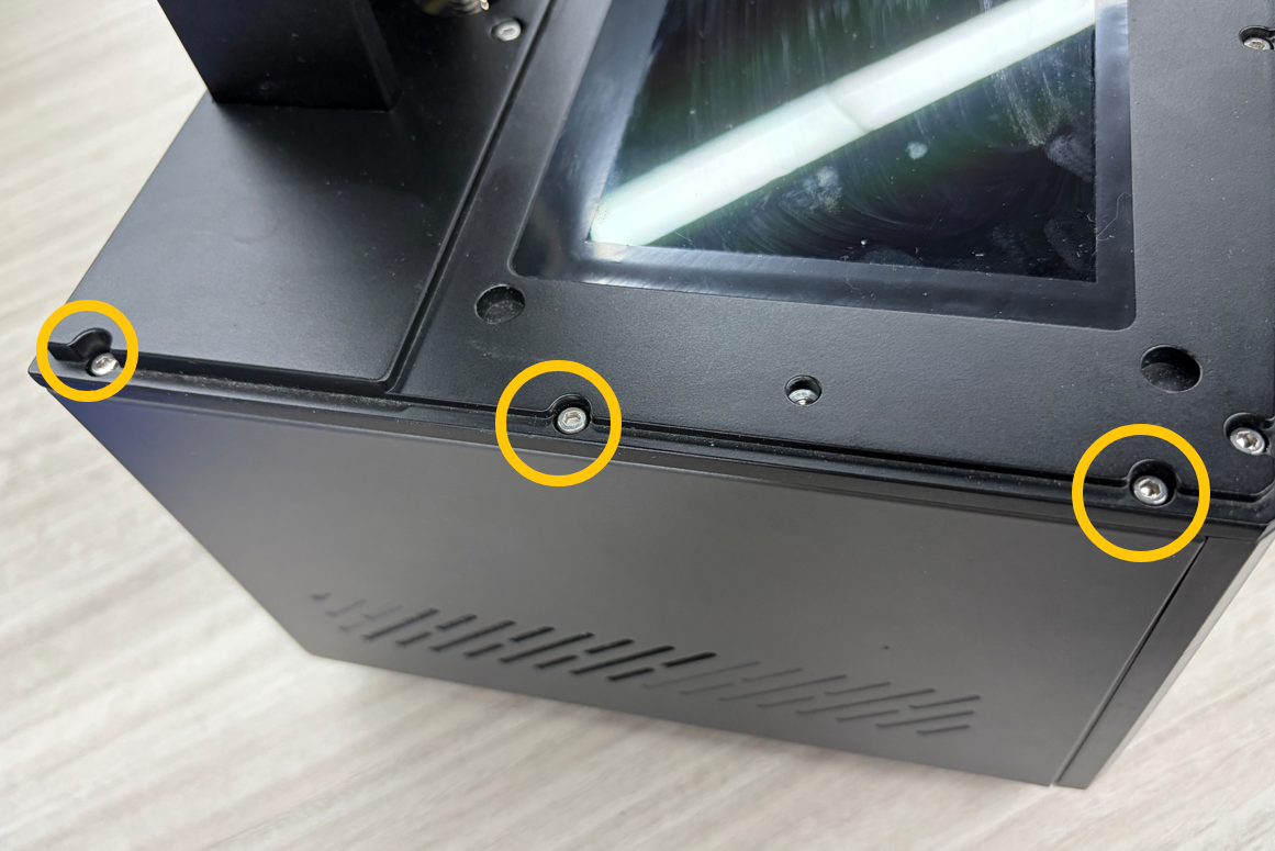
Tighten the three upper screws securing the left panel.
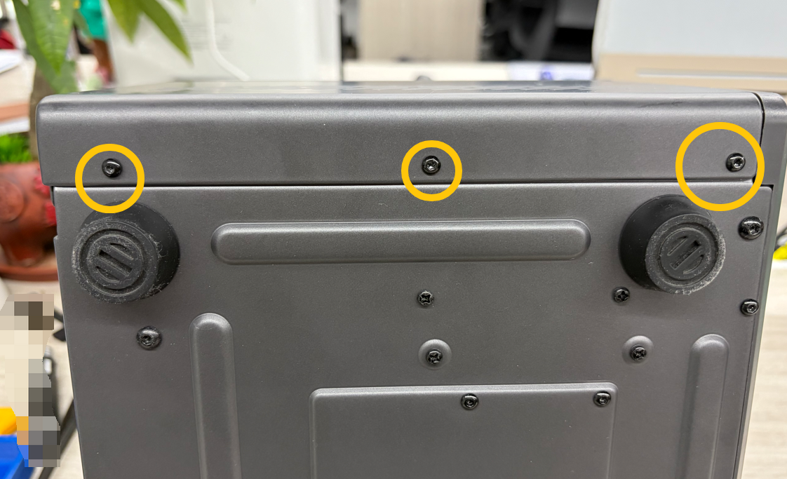
Tighten the three lower screws securing the left panel.
¶ Install Right Panel
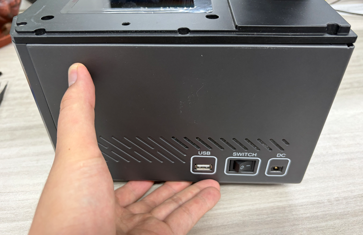
Place the right panel back into position.
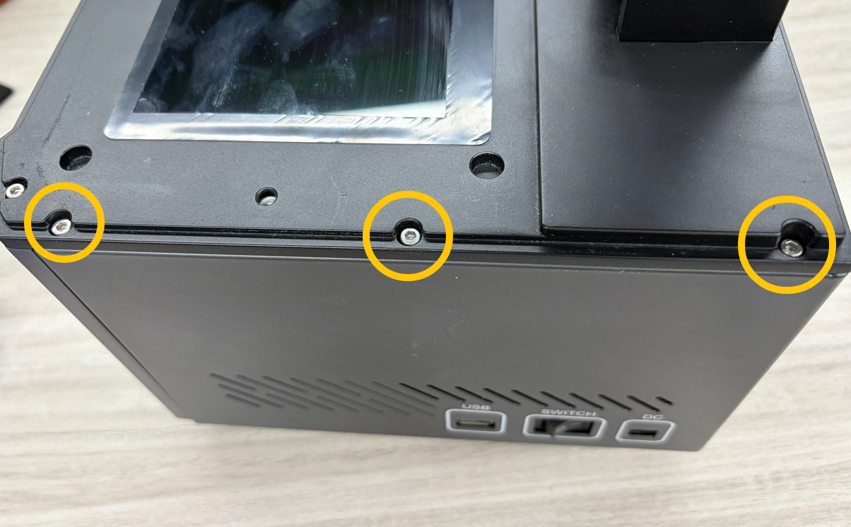
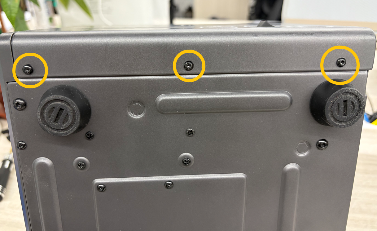
Tighten the three upper screws securing the right panel.
Tighten the three lower screws securing the right panel.
¶ Install Rear Panel
Place the rear panel back into position.
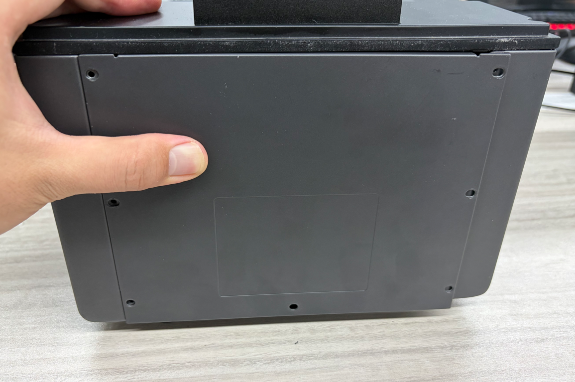
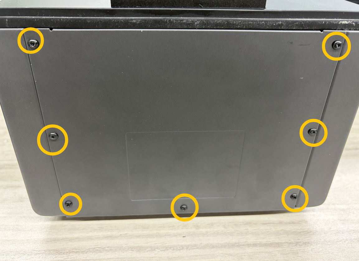
Tighten the seven screws securing the rear panel.
¶ Verification
- Reinstall the Build Plate, Resin Tray, and Anti-UV Cover.
- Plug the adapter into the printer and turn on the Switch.
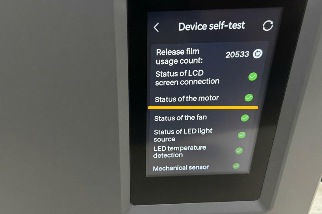
- Confirm that the Touch Screen passes self-check and the Z Axis motor replacement is completed successfully.