¶ Fault Symptoms
After starting a print, the UV light fails to turn on, preventing the model from being cured properly.
¶ Possible Causes
- Incorrect adapter specifications are used.
- Adapter failure.
- Loose connectors on the constant current board.
- Constant current board or mainboard failure.
¶ Required Tools
- 2.0 mm Allen key
- 2.5 mm Allen key
- Multimeter
¶ Troubleshooting Steps
Note:
Some inspection steps require a multimeter. If you do not have a multimeter, please skip the related steps.
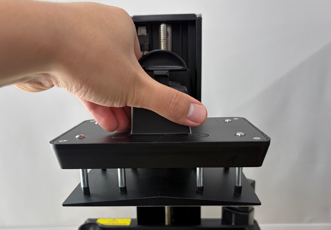
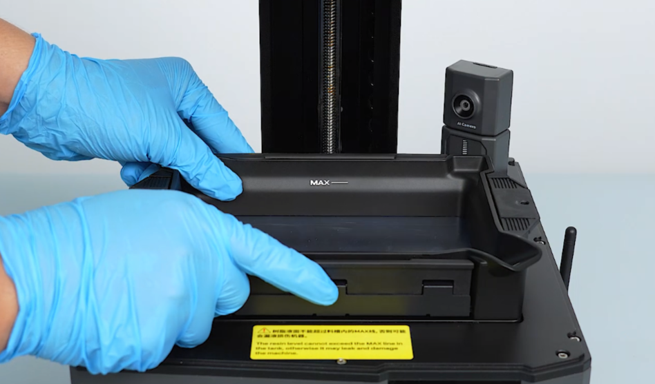
Before troubleshooting, please remove the Resin Tank and Build Plate.
¶ 1. Check the Adapter Specifications
¶ 1.1 Check the Adapter Specifications
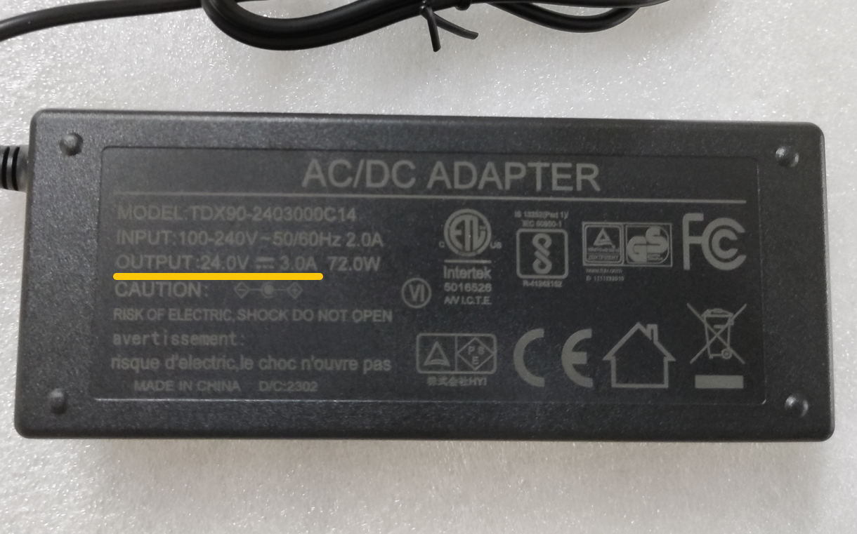
Flip the adapter over and check the specifications label on the back.
The default adapter specification for Mars 5 Ultra is:
24V ⎓ 3A
The specification information can be found on the back of the adapter.
Note:
Some models in the Mercury series use a 12V output adapter, which is not compatible with Mars 5 Ultra.
Do not mix adapters between different models.
¶ 1.2 Check the Adapter Output Voltage with a Multimeter
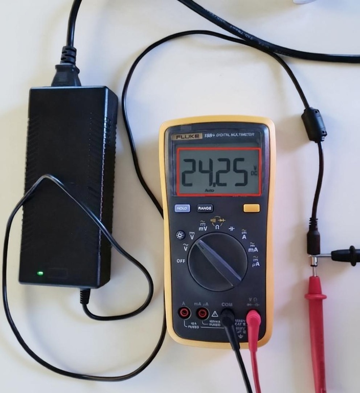
Use a multimeter to check whether the adapter output voltage is 24V.
¶ 1.3 Test with Another 24V Adapter
If you do not have a multimeter, try using another 24V adapter.
Requirements:
- Output current: no less than 3A
- Connector: Must match the original adapter
Check whether the UV light can turn on normally.
Troubleshooting results:
- If the UV light works normally with another adapter, the original adapter is faulty and needs to be replaced.
- If the output voltage is significantly lower than 24V, the adapter may be abnormal and needs to be replaced.
- If the output voltage is normal, continue troubleshooting according to the following steps.
¶ 2. Check the Constant Current Board Connectors
¶ 2.1 Turn Off the Printer
- Turn off the printer.
- Disconnect the adapter.
¶ 2.2 Remove the Rear Panel
Use a 2.0 mm Allen key to remove the seven screws securing the rear panel.
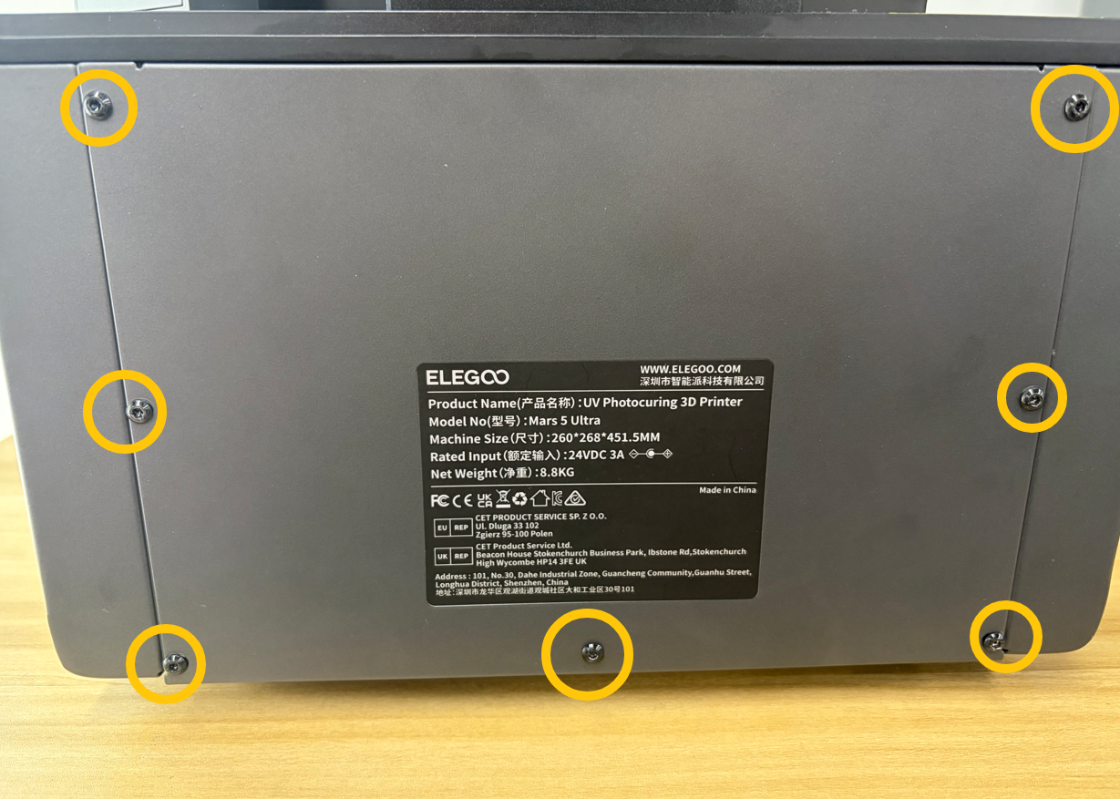
Remove the rear panel.
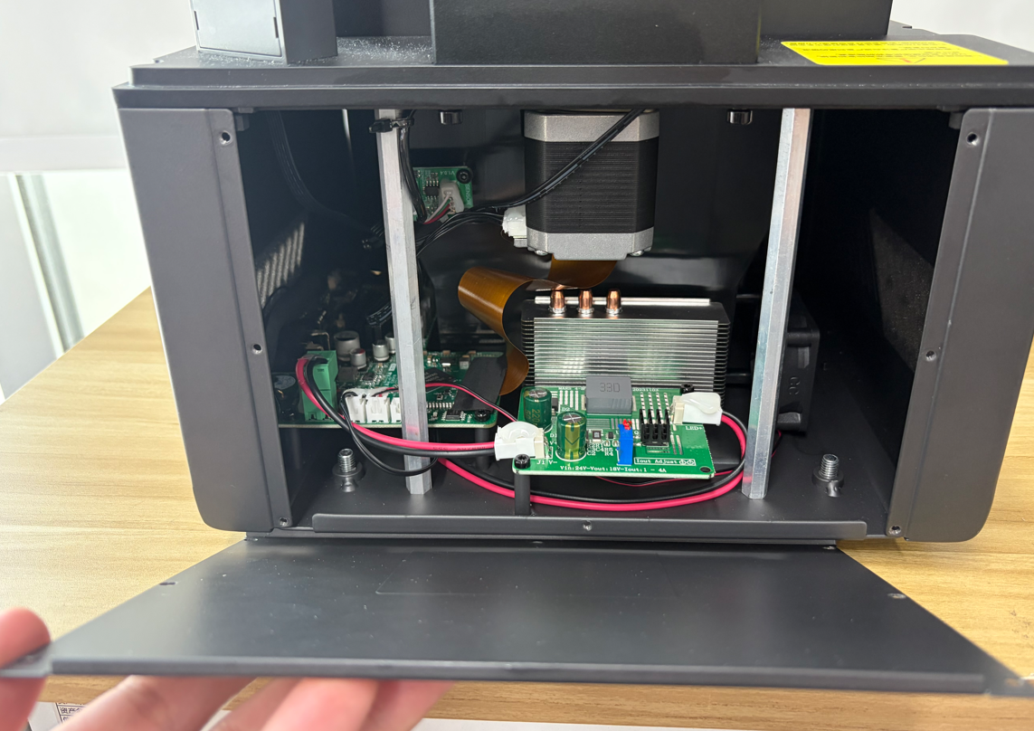
¶ 2.3 Check the Constant Current Board Connectors
Check the three connectors connected to the constant current board.
Confirm whether the connectors are:
- Loose
- Damaged
- Burned
- Discolored
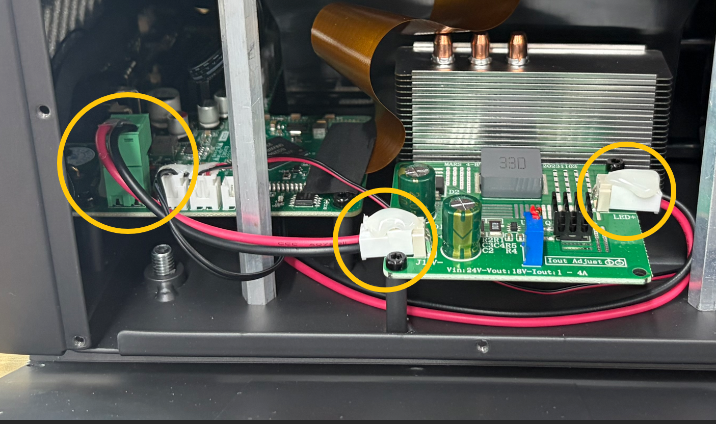
If any damage, burn marks, or discoloration are found:
- Take photos and contact technical support.
- Do not continue using the printer.
- Keep the printer powered off.
Note:
To prevent connectors from becoming loose during transportation, some connectors may be secured with hot glue.
Do not forcibly remove the hot glue if the connectors are properly connected.
If the connectors are properly connected, continue troubleshooting.
Note:
The following steps require inspection inside the printer chassis. Please do not reinstall the rear panel temporarily.
¶ 3. Check the Mainboard Output Voltage
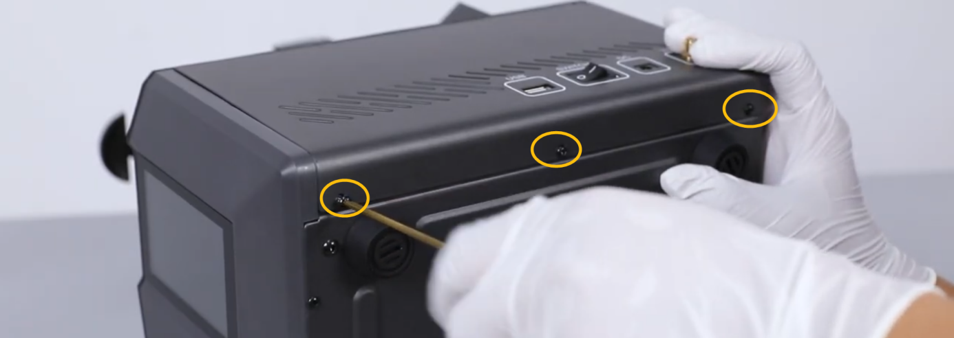
¶ 3.1 Remove the Right Panel
- Use a 2.5 mm Allen key to remove the three screws securing the upper part of the right panel.
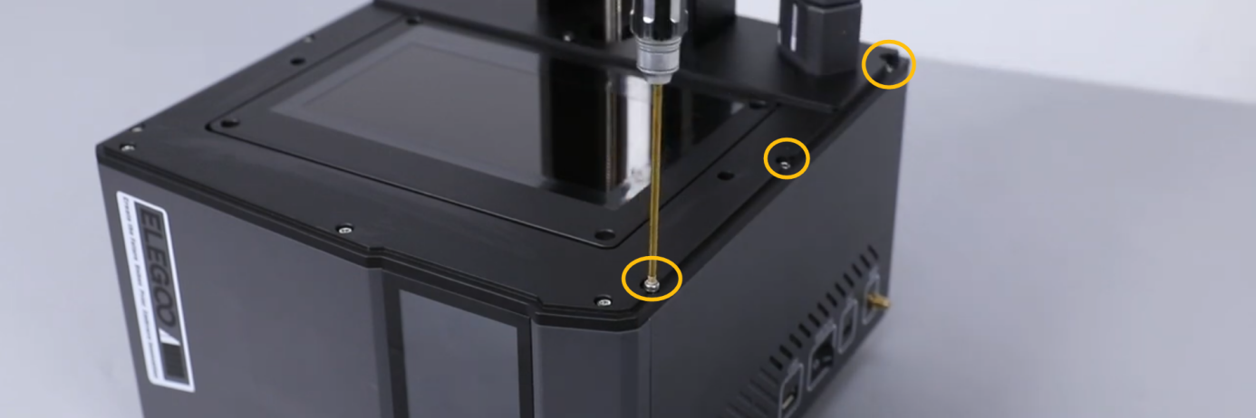
- Use a 2.0 mm Allen key to remove the three screws securing the lower part of the right panel.
Note:
A WiFi antenna is connected between the right panel and the mainboard.
Be careful not to damage the antenna when removing the right panel.
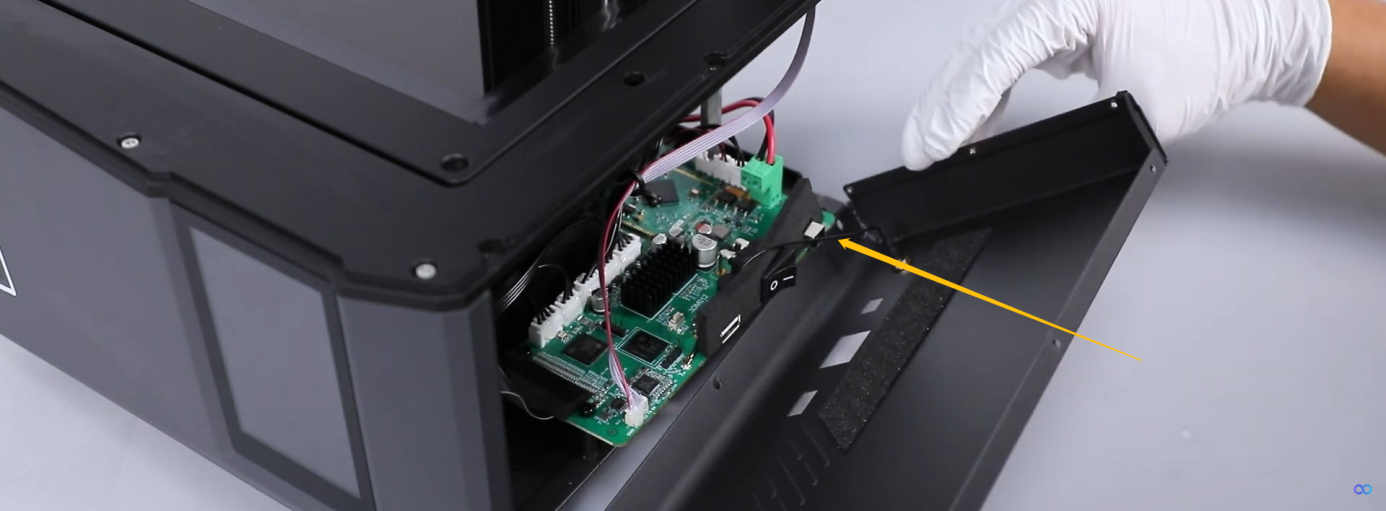
- Disconnect the WiFi antenna connector and remove the right panel.
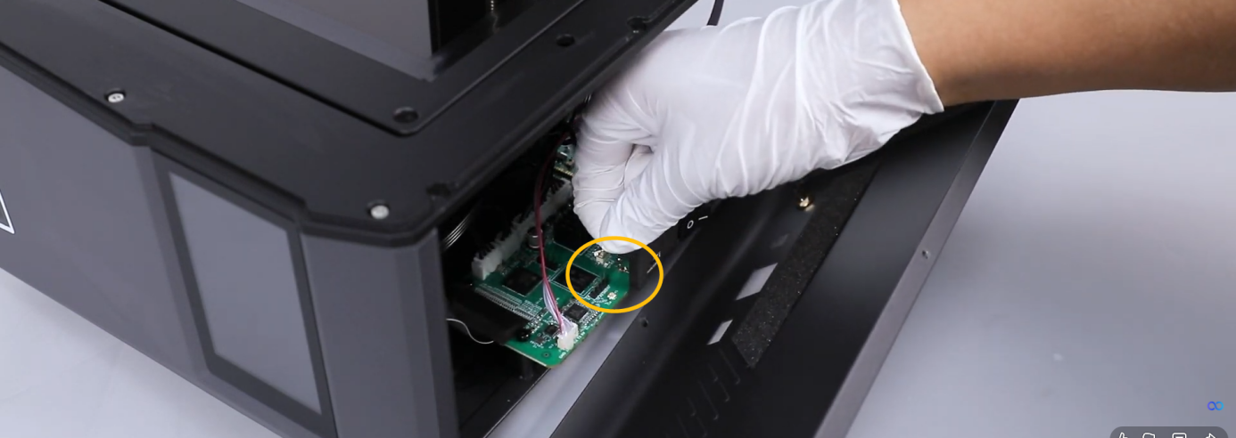
¶ 3.2 Measure the Mainboard Output Voltage
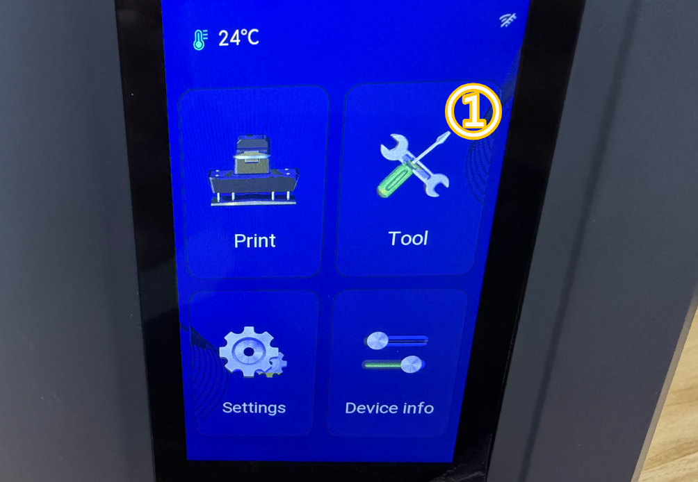
- Turn on the printer.
- Set the LCD exposure time to more than 30 seconds through the touchscreen.
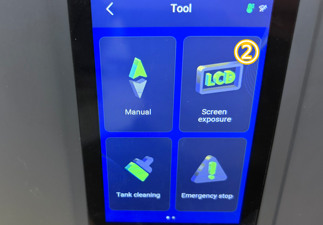
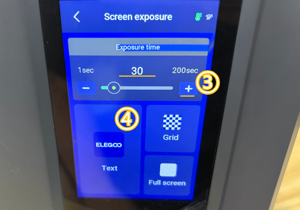
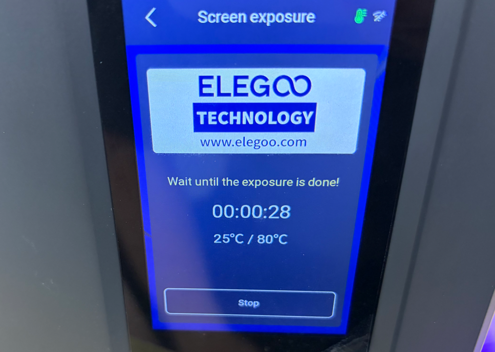
- Set the multimeter to DC voltage mode (200V).
- Measure the output voltage at the UV light terminals shown below.
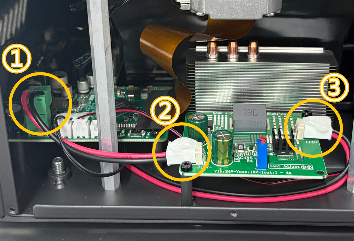
Safety Notice:
Do not look directly at the UV light source during measurement.
It is recommended to wear protective glasses or use a shield to avoid direct UV exposure.
Note:
Make sure the multimeter probes do not touch other components.
The measured value may fluctuate slightly.
Under normal conditions:
- The output voltage at points ① and ② should be approximately 24V.
- The output voltage at point ③ should be approximately 18V.
¶ Troubleshooting Results
| Measurement Result | Possible Cause |
|---|---|
| No output voltage at point ① | The mainboard may be faulty. |
| Output voltage at point ① but no output voltage at point ② | The adapter extension cable connector at position ② may be loose or have poor contact. |
| Output voltage at points ① and ② but no output voltage at point ③ | The constant current board may be faulty. |
| Output voltage at points ①, ②, and ③, but UV light does not turn on | The UV light board may be faulty. |
¶ Contact Technical Support
When contacting technical support, please provide the following information:
Email: 3dp@elegoo.com
- Video — Record a video showing the UV light failing to turn on.
- Inspection result — Whether the adapter specifications are correct.
- Inspection result — Whether the adapter output voltage is 24V.
(Skip this step if you do not have a multimeter.) - Inspection result — Whether the UV light can turn on when using another 24V adapter.
- Inspection result — Whether the constant current board connectors are loose, discolored, or damaged.
- Inspection result — Whether the mainboard output port has 24V output voltage.
(Skip this step if you do not have a multimeter.)
¶ Help us improve
If you have any ideas about the wiki pages, please let us know via ELEGOO official feedback channel