¶ Operation Steps for Each Model
The steps below are based on Centauri 2 Combo. For Centauri 2, skip the steps related to parts that are not installed.
| Model | Action | Steps to Skip |
|---|---|---|
| Centauri Carbon 2 Combo | Follow all steps | None |
| Centauri Carbon 2 | Skip CANVAS-related steps and lid removal step |
|
| Centauri 2 Combo | Skip enclosure-related steps only if the enclosure is not installed |
|
| Centauri 2 | Skip CANVAS-related steps and lid removal step |
|
If your printer has optional accessories installed, such as CANVAS or an enclosure, follow the steps related to those parts.
¶ Tutorial Video
https://www.youtube.com/watch?v=94QG6iGcYe8
¶ Tools and Materials
-
A 1.5 mm Allen key
-
A 2.0 mm Allen key
-
A 3.0 mm Allen key
-
A pair of tweezers
-
A Phillips screwdriver
-
A pair of pliers
-
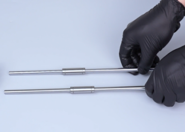
New XY rods and the XY bearings
¶ Tutorial Video
https://www.youtube.com/watch?v=94QG6iGcYe8
¶ Instruction
¶ Preparation
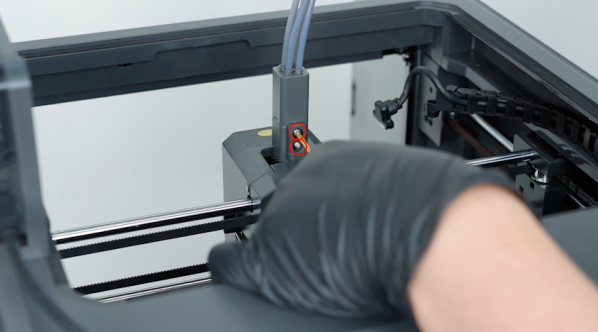
Turn the power switch OFF (symbol ""〇""). Unplug the power supply cable.
¶ Remove the 4-in-1 hub
-
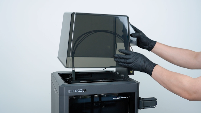
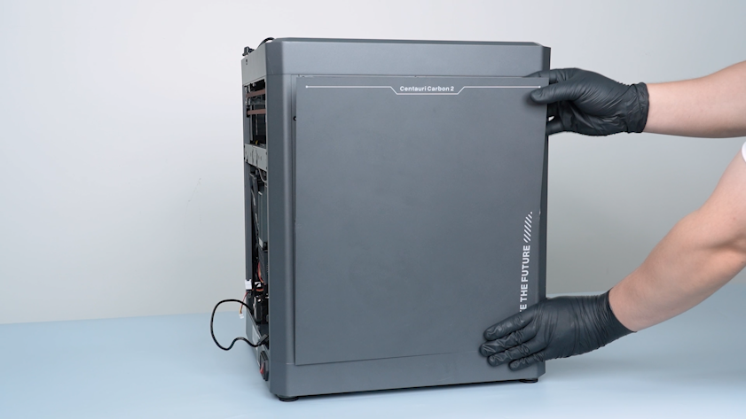
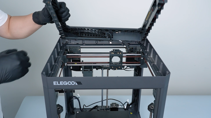
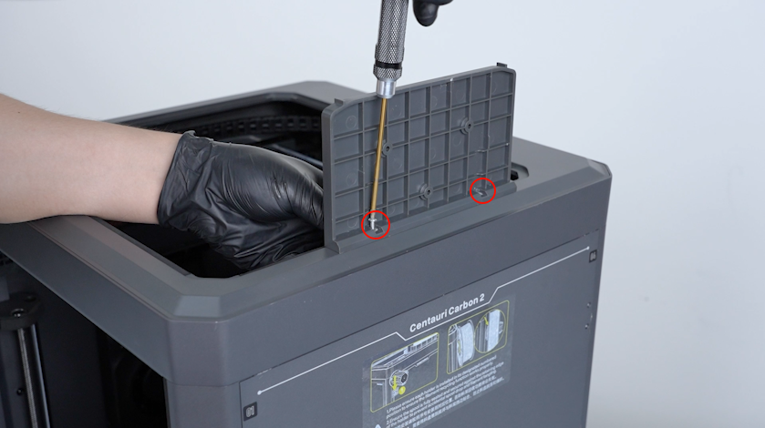
Remove the lid.
-
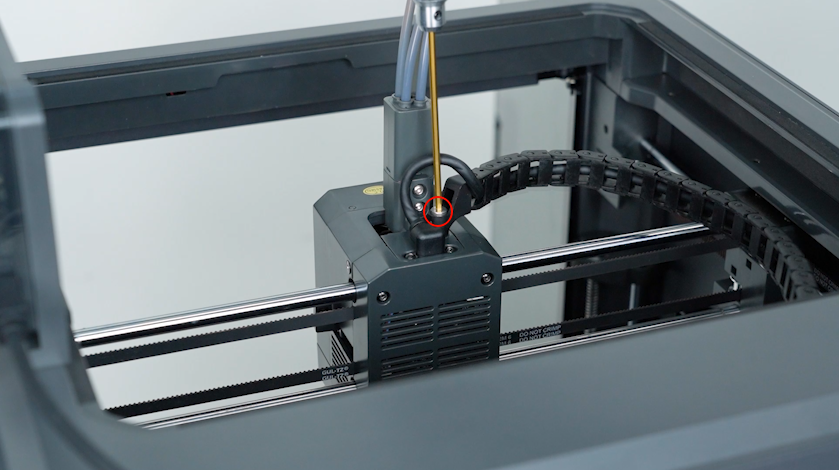
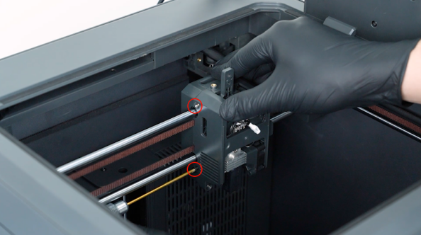
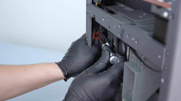
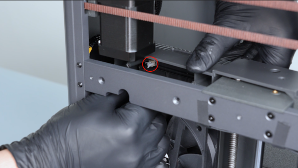
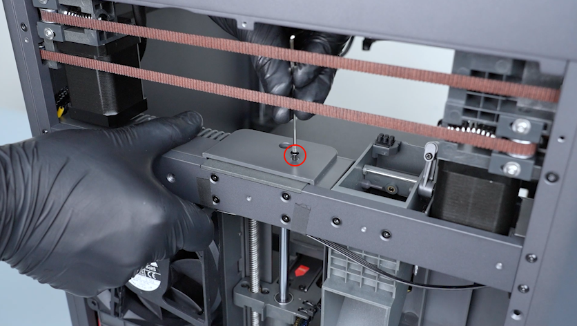
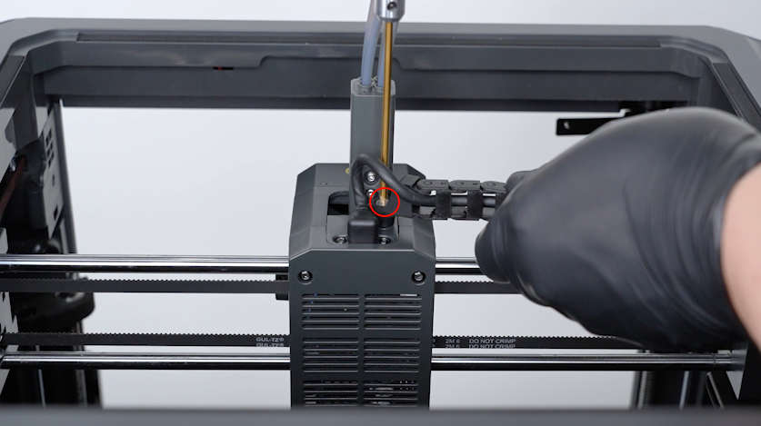
Release and remove the screw securing the tank chain with a 2.5 mm Allen key.
-
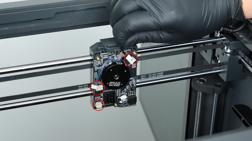
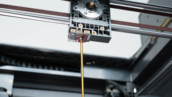
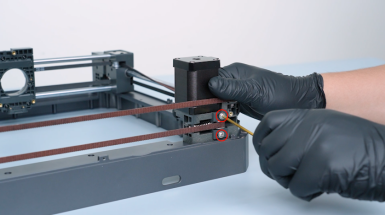
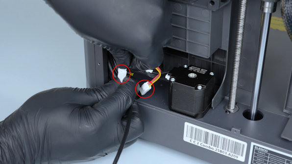
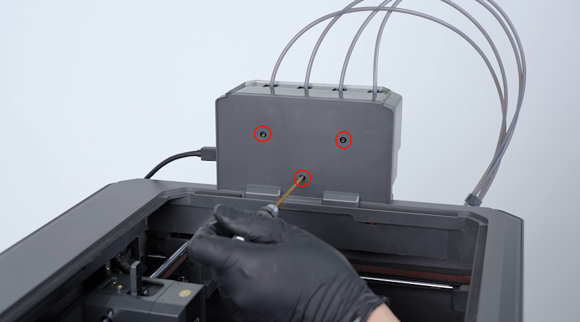
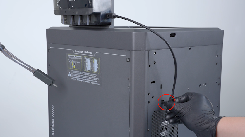
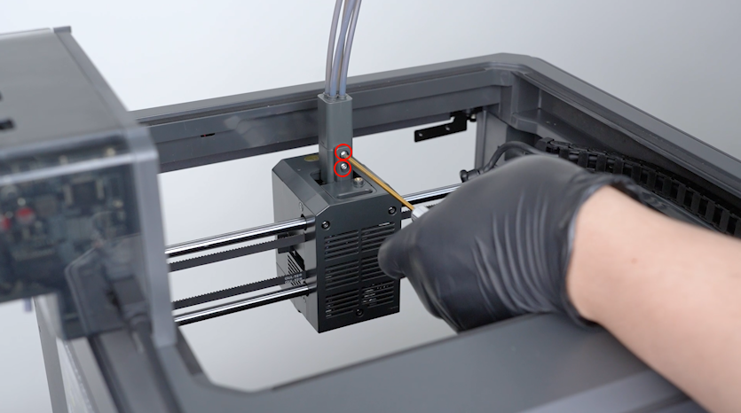
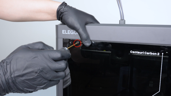
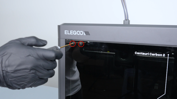
Release and remove the two screws securing the CAN bus with a 1.5 mm Allen key. Unplug the CAN bus.
-
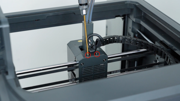
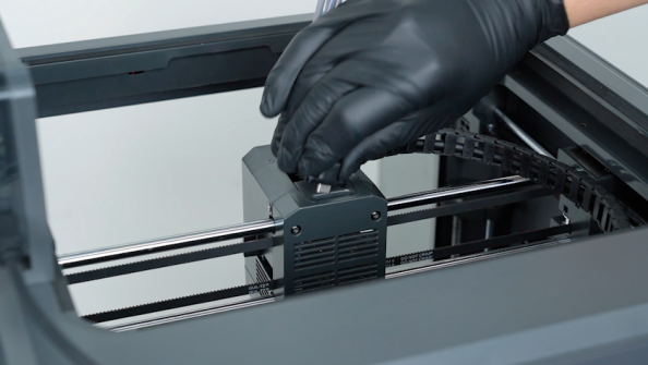
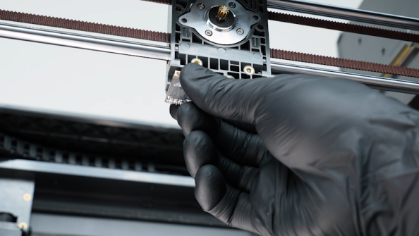
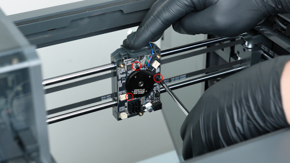
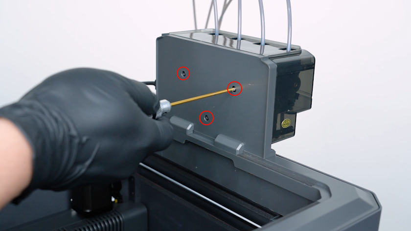
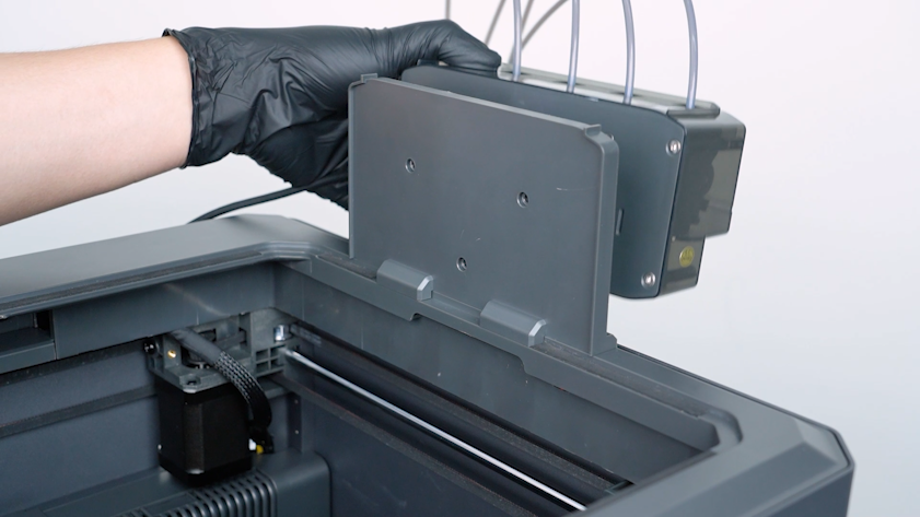
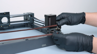
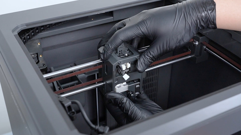
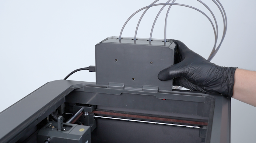
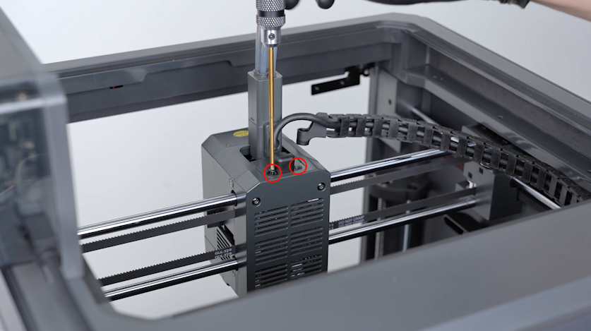
Release and remove the two screws securing the 4-in-1 hub with a 2.0 mm Allen key. Remove the 4-in-1 hub.
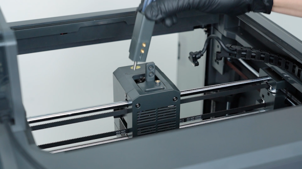
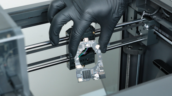
¶ Remove the gearbox assembly
-
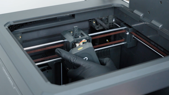
Remove the front cover of the tool head. Unplug the cable of the model cooling fan and remove the front cover of the tool head.
-
Release and remove the four screws securing the tool head housing with a 2.0 mm Allen key. Remove the front cover of the tool head housing.
-
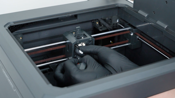
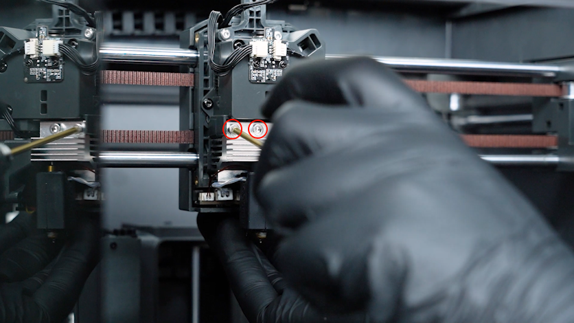
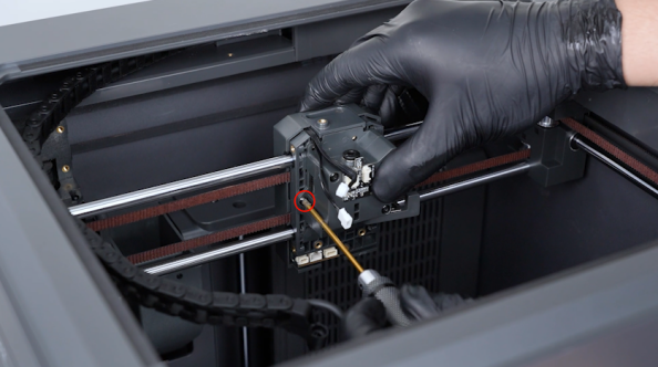
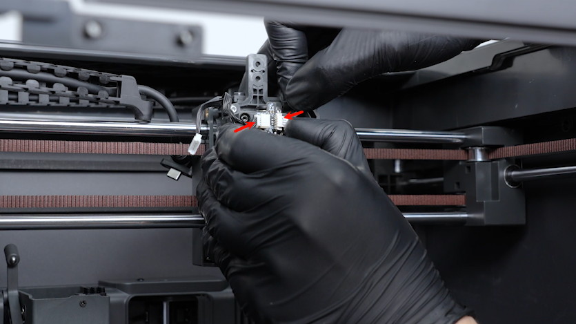
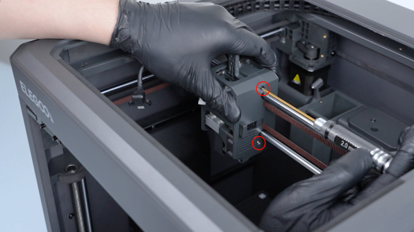
Release and remove the two screws securing the hotend with a 2.5 mm Allen key.
-
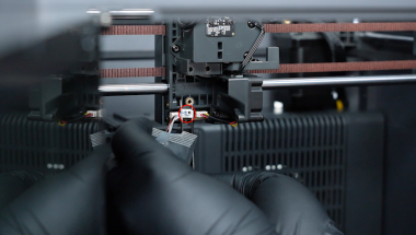
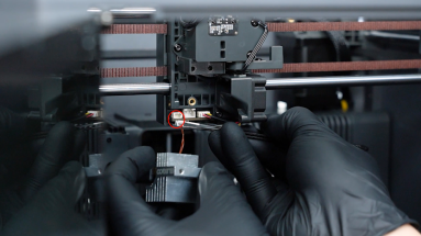
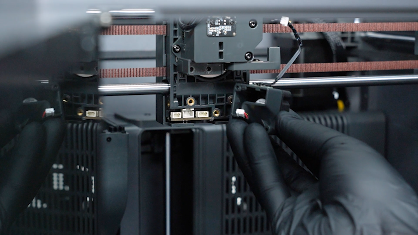
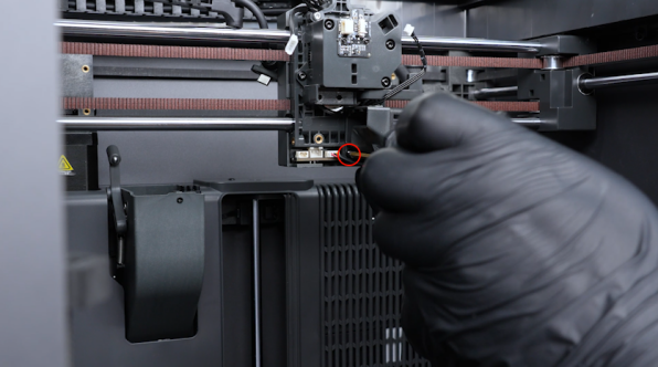
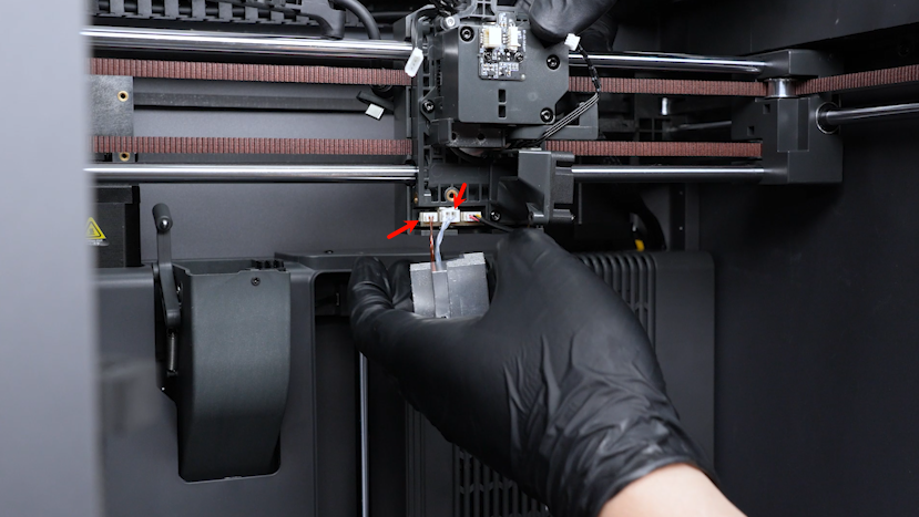
Unplug the cables of the thermistor, ceramic heating plate and the heat break cooling fan with a pair of tweezers.
-
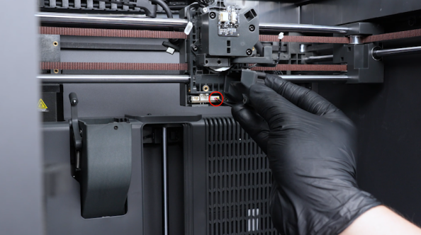
Unplug the cable of the filament detection board.
-
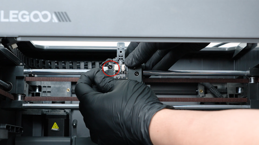
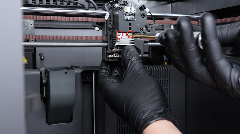
Release and remove the screw securing the heat break cooling fan with a 2.0 mm Allen key.
-
Remove the heat break cooling fan assembly.
-
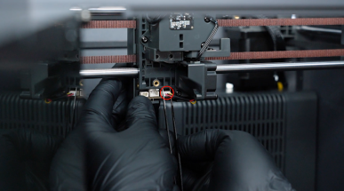
Unplug the other cable of the filament detection board.
-
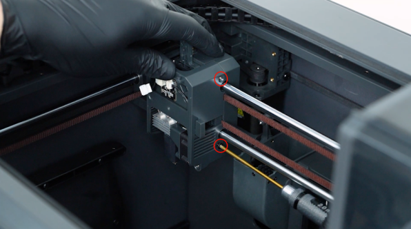
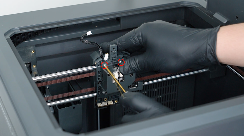
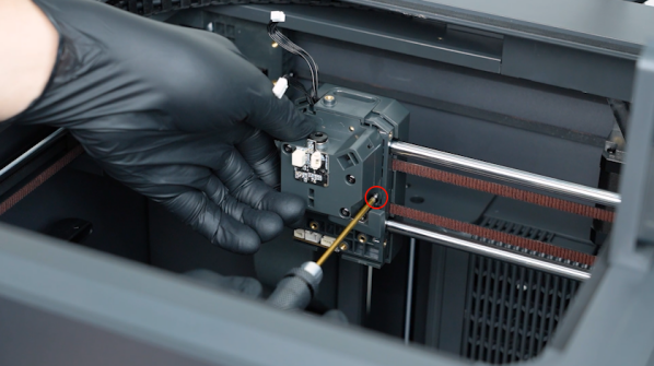
Release and remove the two screws securing the 4-in-1 hub holder with a 2.0 mm Allen key.
-
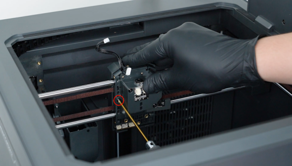
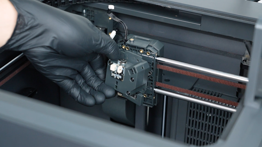
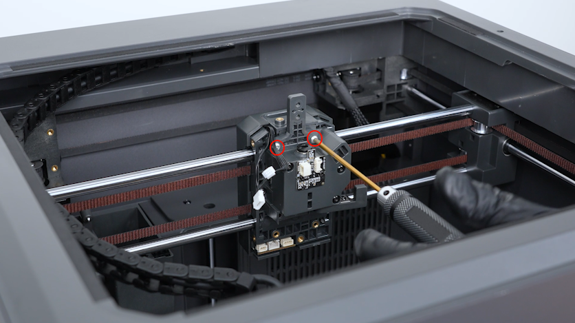
Release and remove the two screws securing the gearbox assembly with a 2.0 mm Allen key.
-
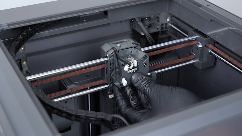
Remove the gearbox assembly.
¶ Remove the CANVAS and the CANVAS holder
-
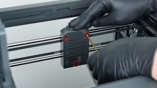
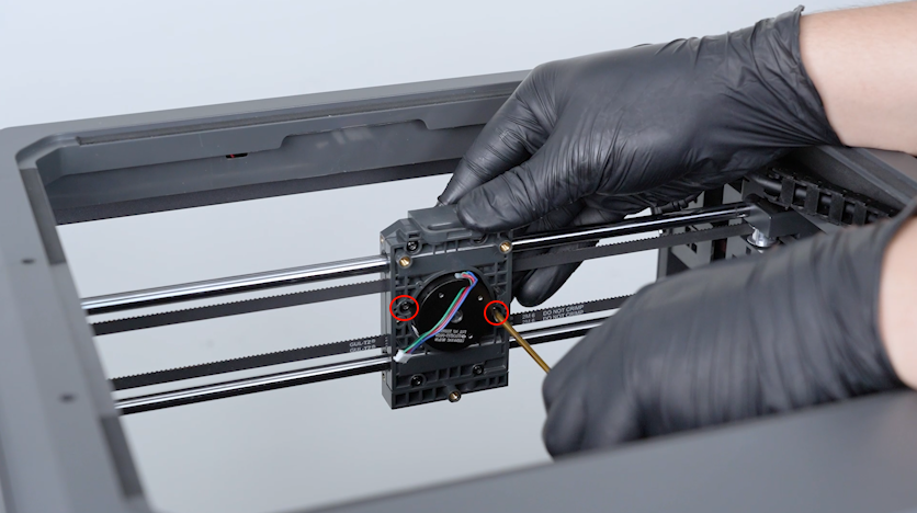
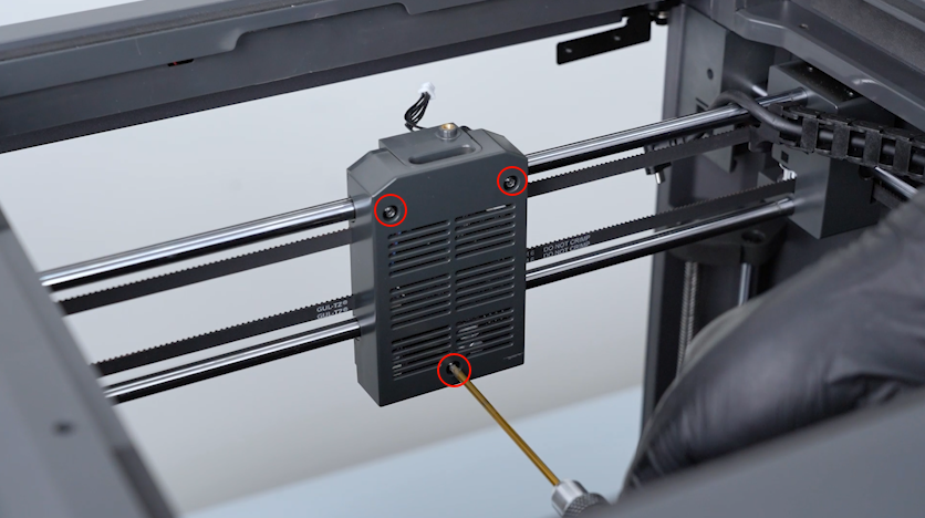
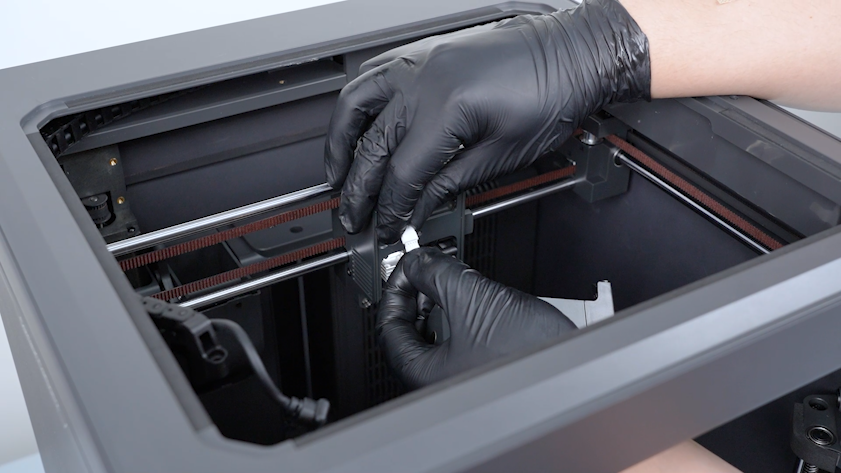
Release and remove the three screws securing the back cover of the tool head with a 2.0 mm Allen key. Remove the back cover of the tool head.
-
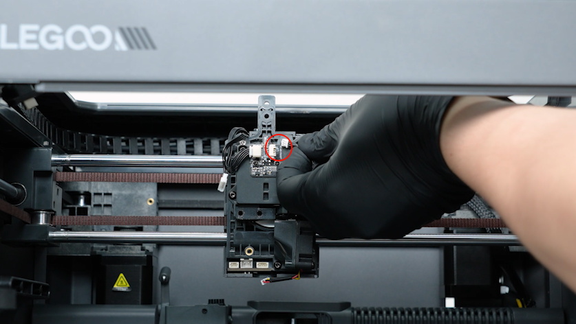
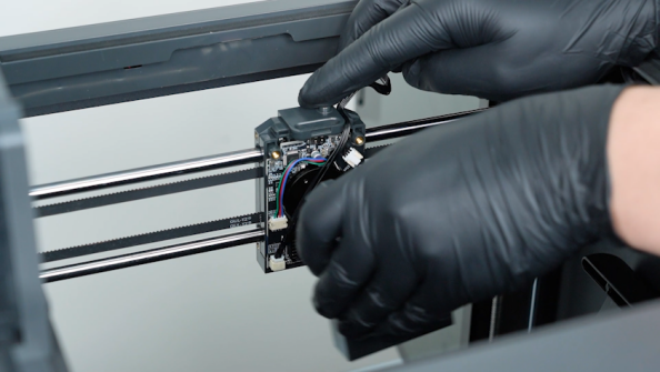
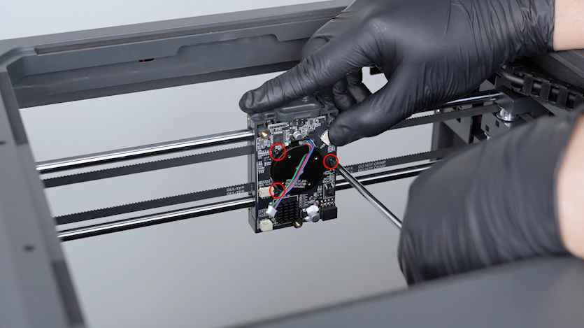
Unplug the communication board adapter cable, E motor cable and the model cooling fan cable.
-
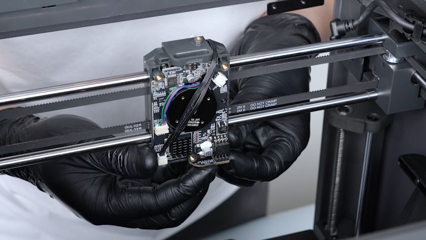
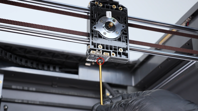
Release and remove the screw securing the tool head board with a 2.0 mm Allen key. Remove the tool head board.
-
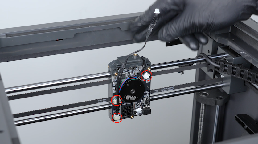
Release and remove the three screws securing the communication board with a Phillips screwdriver. Remove the communication board.
-
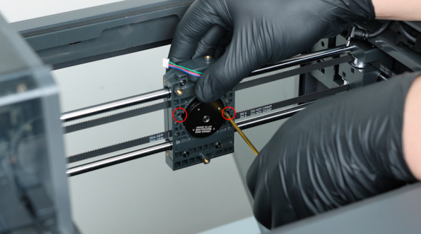
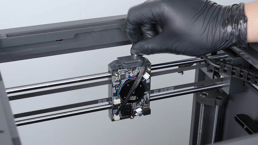
Release and remove the two screws securing the E motor with a 2.0 mm Allen key. Remove the E motor.
-
Unplug the CANVAS communication cable.
-
Release and remove the three screws securing the CANVAS with a 2.0 mm Allen key.
Note: Hold the CANVAS when releasing the last screw.
-
Remove the CANVAS.
-
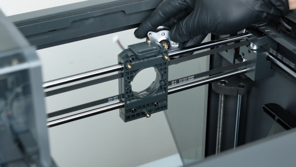
Release and remove the two screws securing the CANVAS holder with a 2.0 mm Allen key.
-
Remove the CANVAS holder.
¶ Remove the filament spool holders and spool holder pallets
-
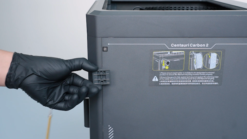
Remove the four spool holders.
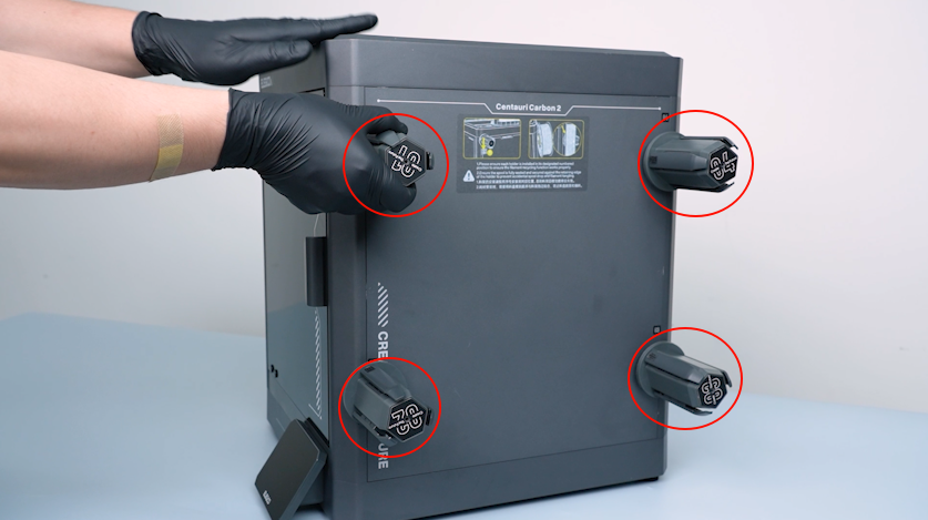
-
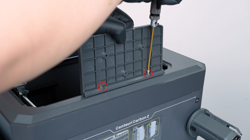
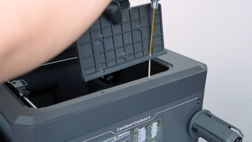
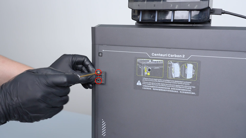
Release and remove the two screws securing the spool holder pallet with a 2.5 mm Allen key and remove the pallet.
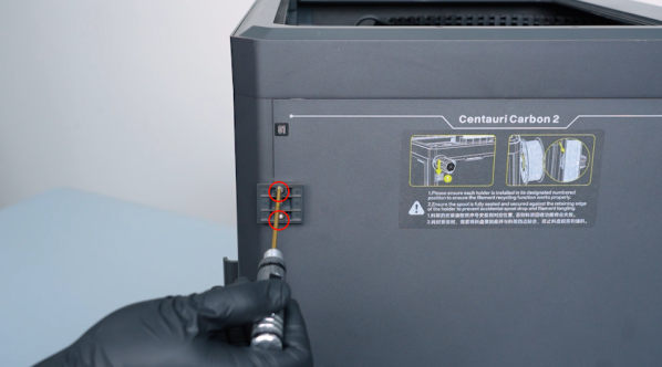
-
Remove the other spool holder pallets in the same way.
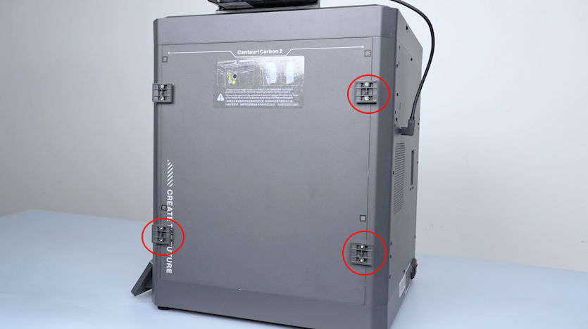
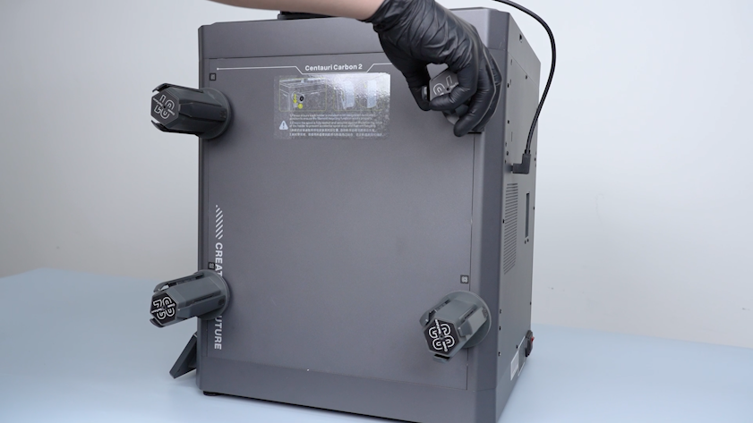
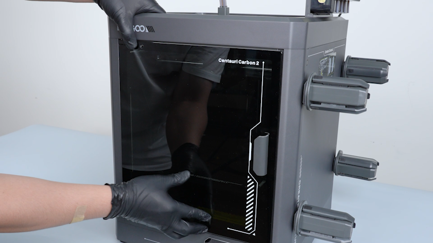
¶ Remove the front door
-
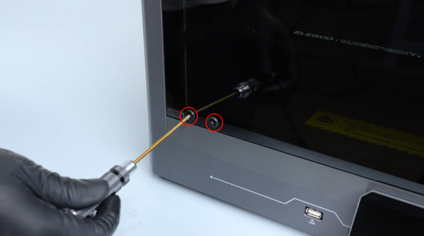
Release and remove the four screws securing the front door with a 2.0 mm Allen key.
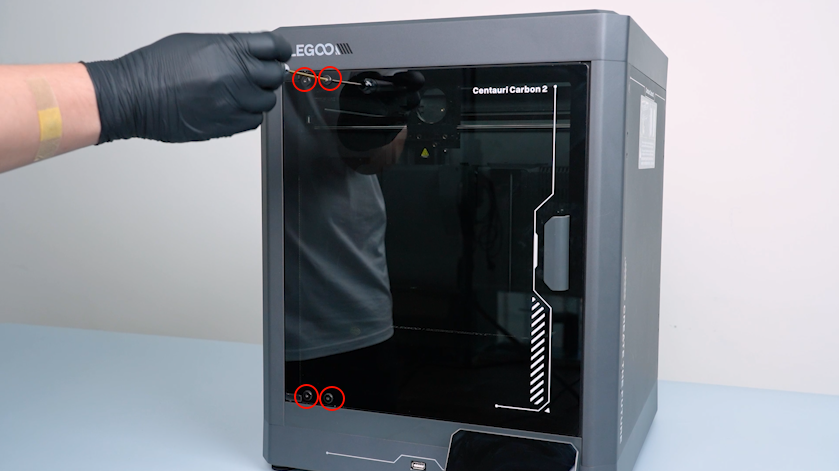
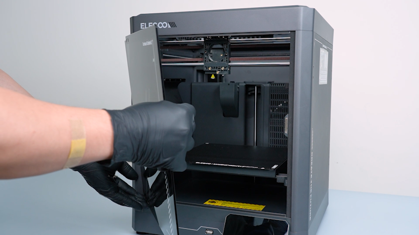
-
Remove the front door.
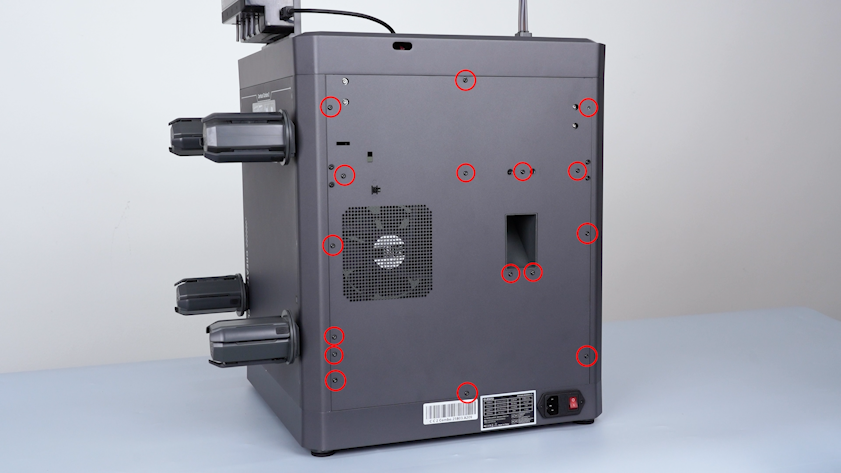
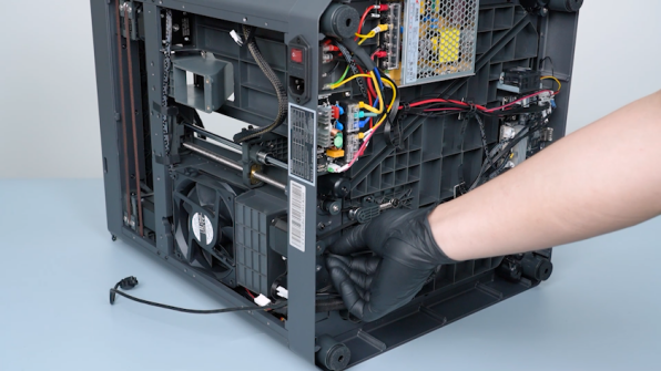
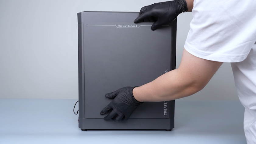
¶ Remove the back cover and the bottom cover
-
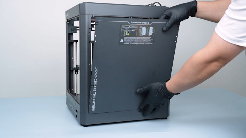
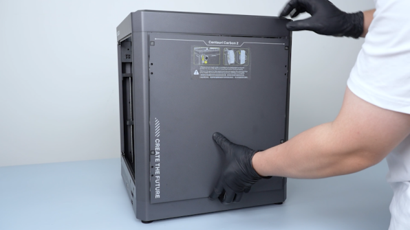
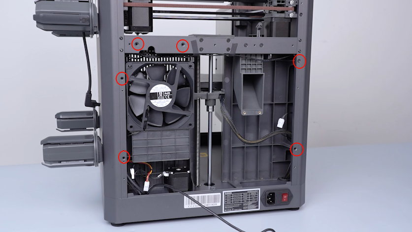
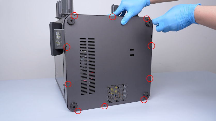
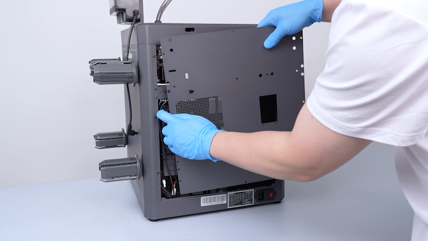
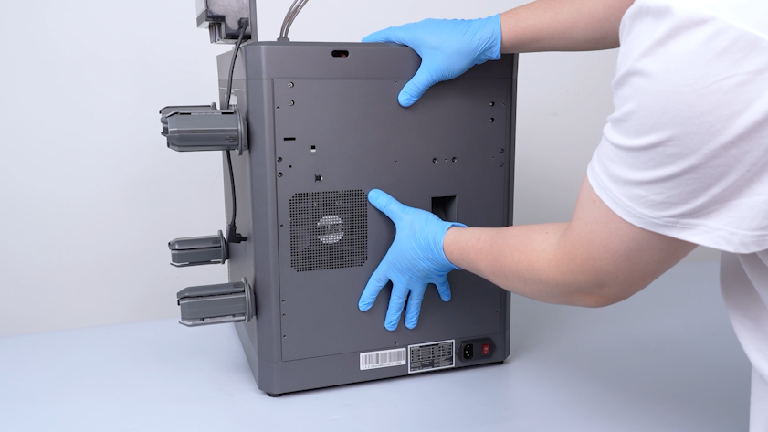
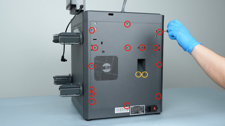
Release and remove the sixteen screws securing the back cover with a 2.0 mm Allen key.
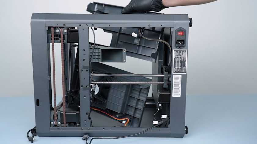
-
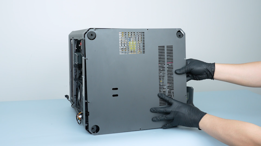
Lay the back cover flat on the table.
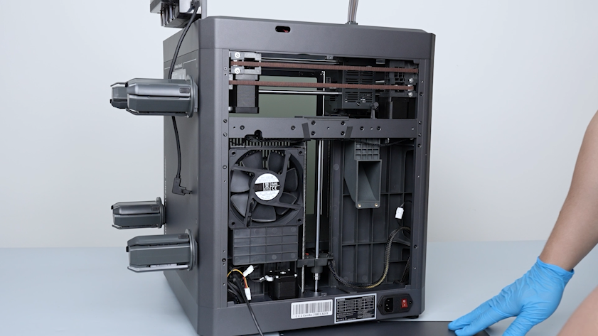
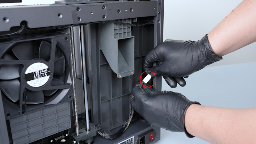
-
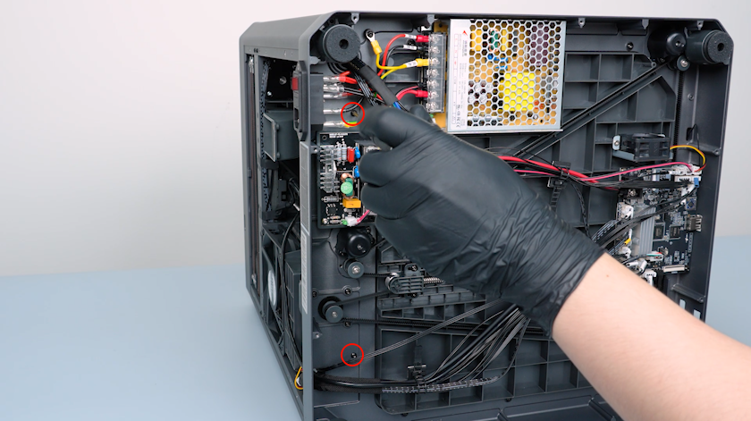
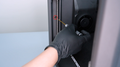
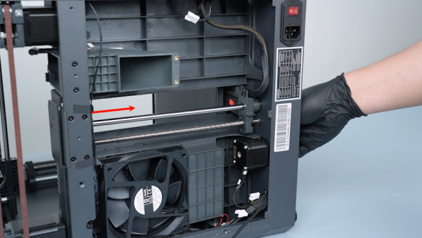
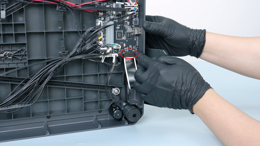
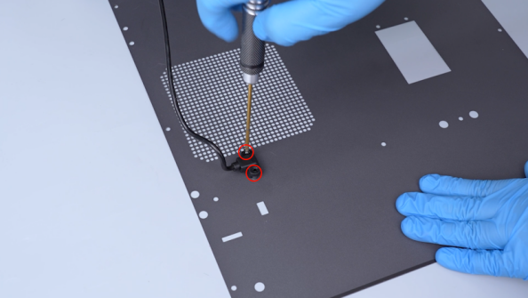
Release and remove the two screws securing the CANVAS extension cable with a 2.0 mm Allen key.
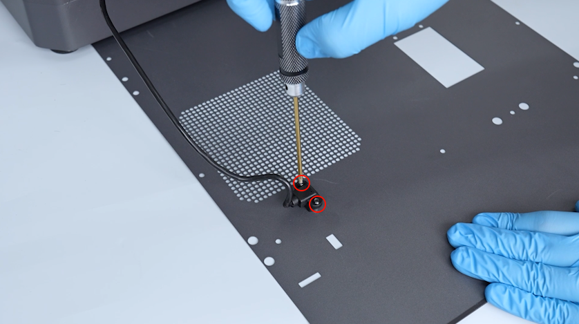
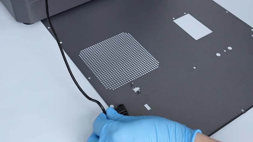
-
Unplug the CANVAS extension cable and remove the back cover.
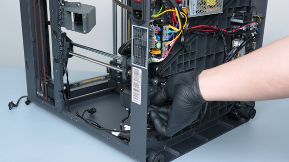
-
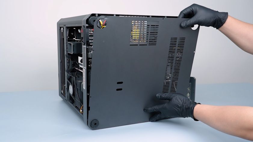
Release and remove the ten screws securing the bottom cover with a 2.0 mm Allen key.
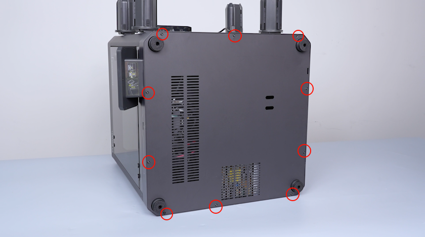
-
Remove the bottom cover.
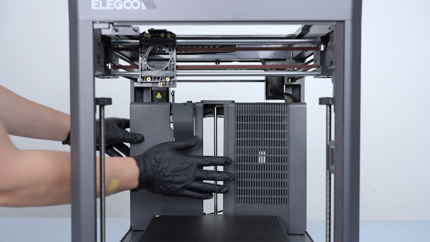
¶ Remove the right cover, partition and the left cover
-
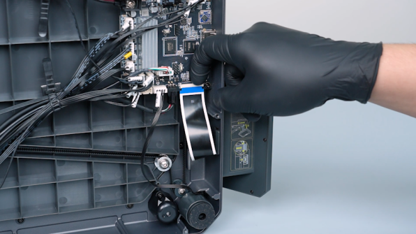
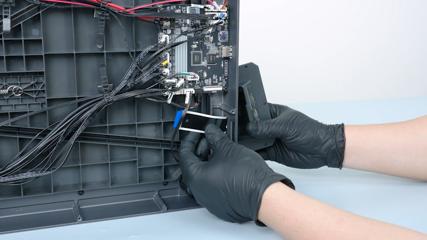
Remove the tape securing the touch screen ribbon cable.
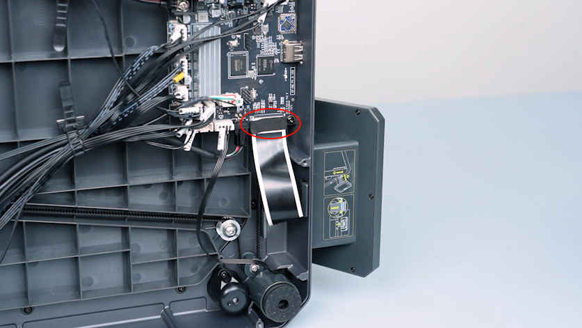
-
Lift the clip and unplug the touch screen ribbon cable.
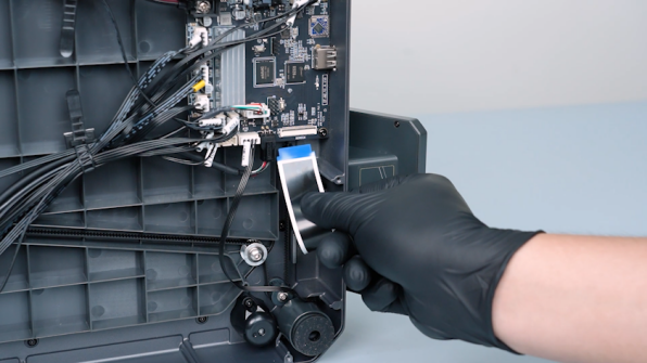
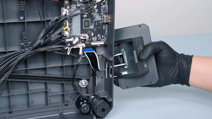
-
Remove the touch screen.
-
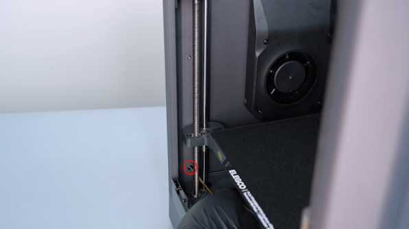
Release and remove the two screws securing the bottom of the partition with a 2.0 mm Allen key.
-
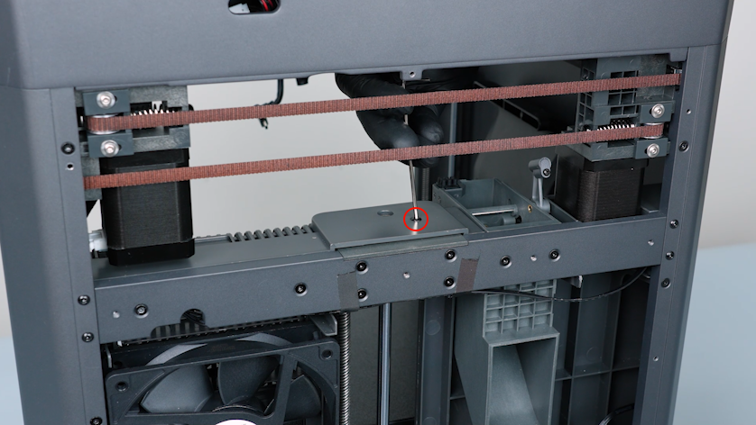
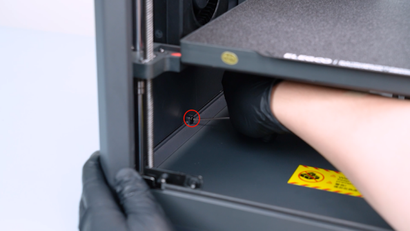
Release and remove the screw securing the upper of the partition with a 2.0 mm Allen key.
-
Release and remove the six screws securing the partition with a 2.0 mm Allen key.
-
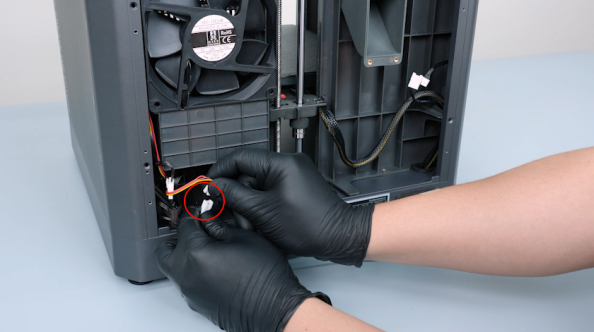
Unplug the cable of the servomotor detection board.
- Unplug the auxiliary cooling fan cable.
-
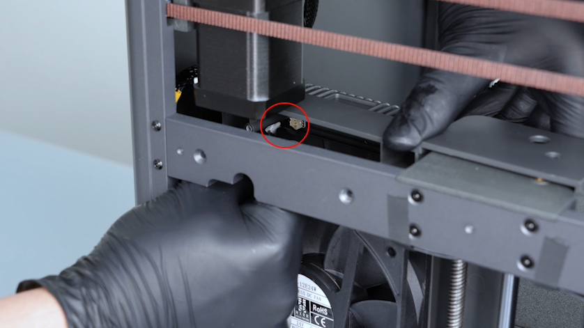
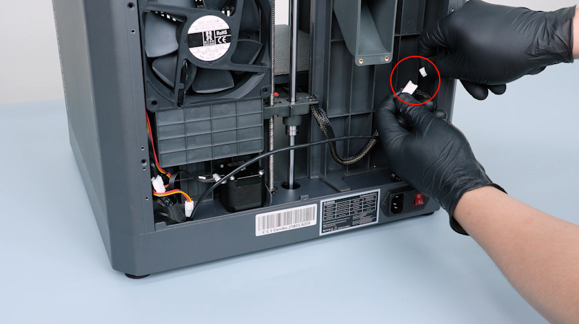
Unplug the servomotor adapter cable and the chamber cooling fan cable.
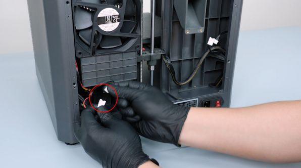
-
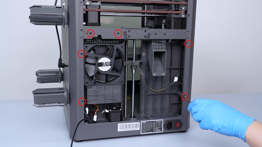
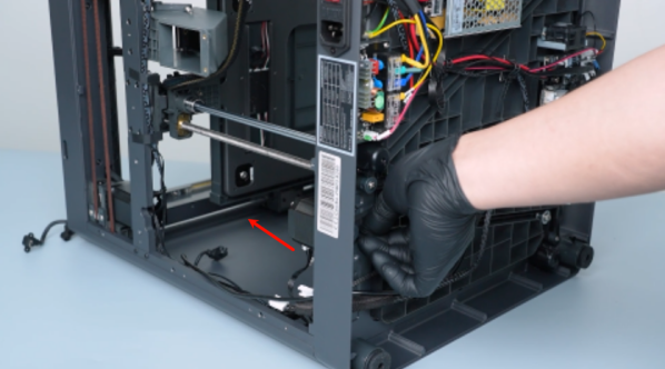
Release and remove the eight screws securing the right cover with a 2.0 mm Allen key.
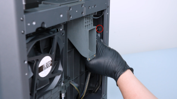
-
Remove the right cover carefully.
-
Remove the auxiliary cooling fan cable from the gap of the partition.
-
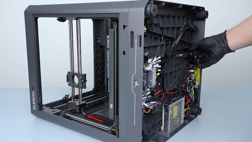
Pull the Z-axis timing belt to lower the heated bed to the bottom of the printer.
-
Remove the partition.
-
Pull the Z-axis timing belt to raise the heated bed to the top of the printer.
-
Release and remove the eight screws securing the left cover with a 2.0 mm Allen key.
-
Remove the left cover.
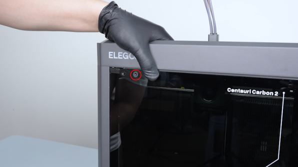
¶ Remove the upper frame
-
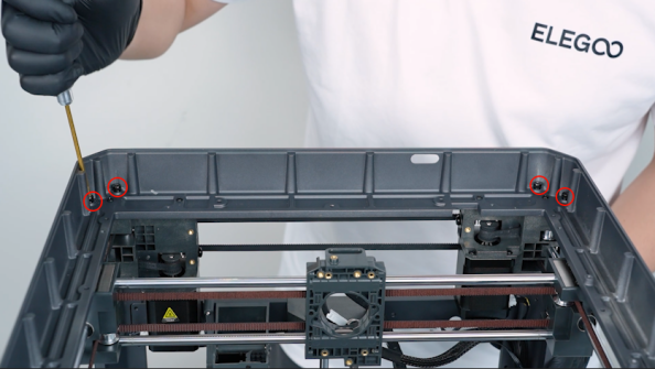
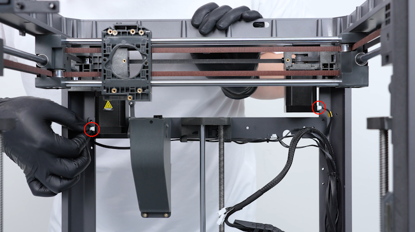
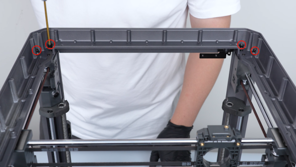
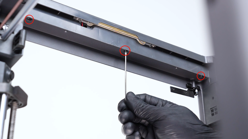
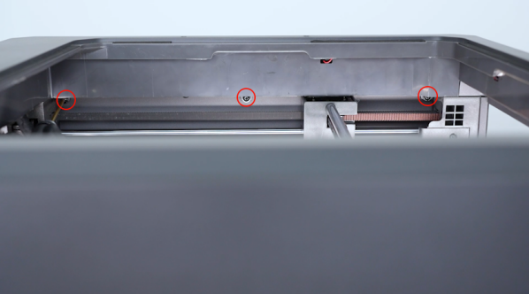
Release and remove the three screws securing the front side of the upper frame housing with a 2.0 mm Allen key.
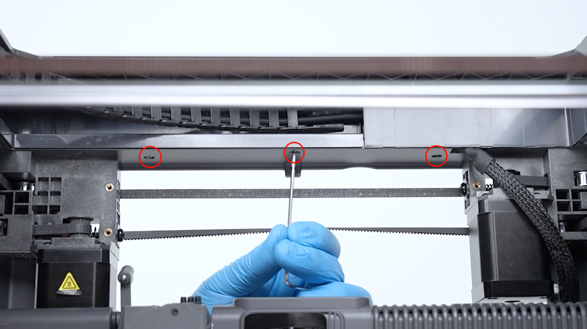
-
Release and remove the four screws securing the left side of the upper frame housing with a 2.0 mm Allen key.
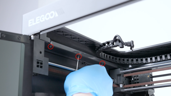
-
Release and remove the three screws securing the right side of the upper frame housing with a 2.0 mm Allen key.
-
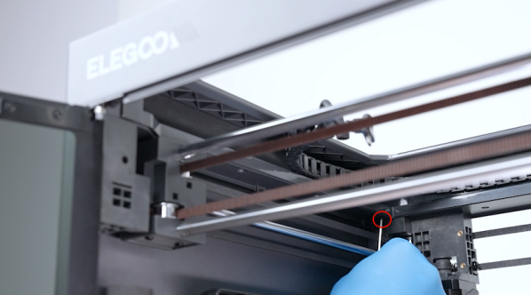
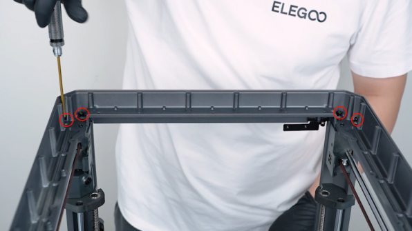
Release and remove the three screws securing the back side of the upper frame housing with a 2.0 mm Allen key.
-
Open the upper frame housing carefully.
-
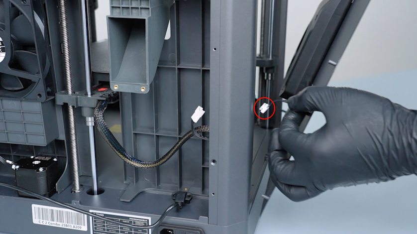
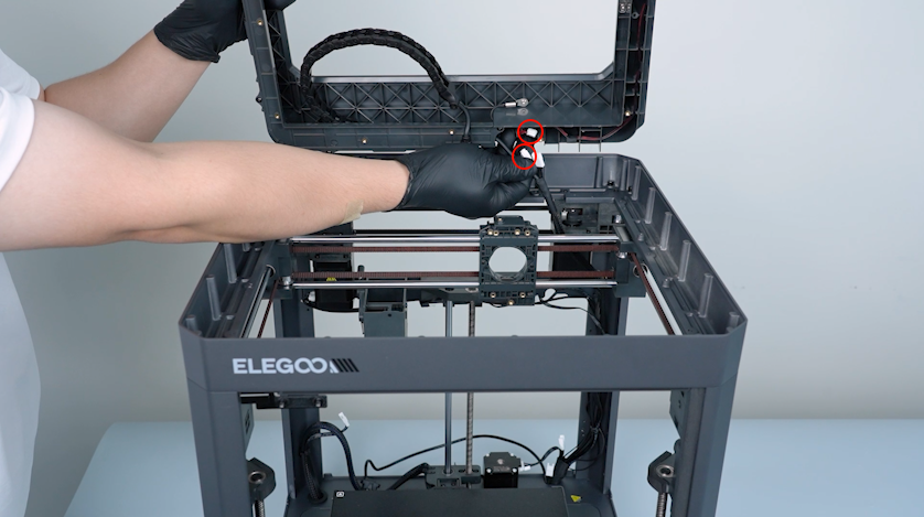
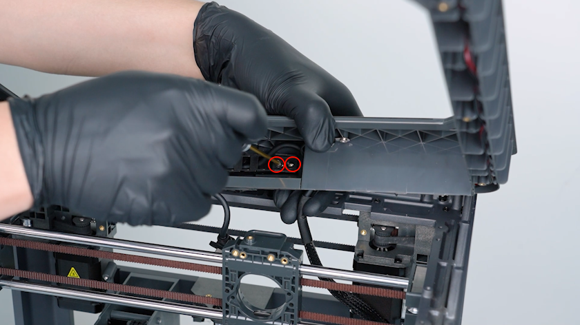
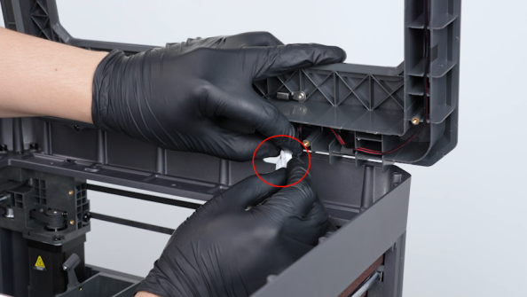
Unplug the cables of the LED and the chamber thermistor.
-
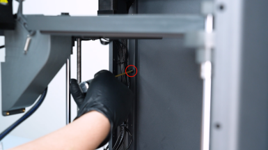
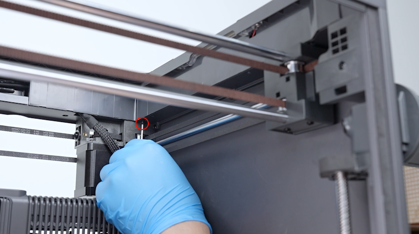
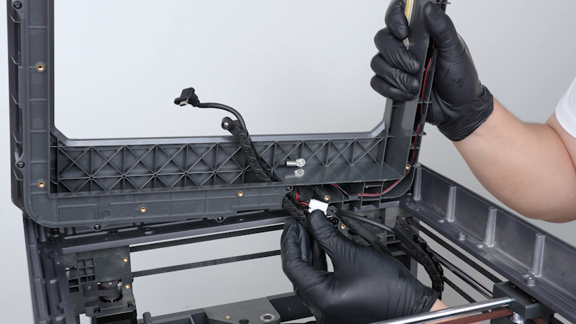
Release and remove the two screws securing the tank chain with a 2.0 mm Allen key.
-
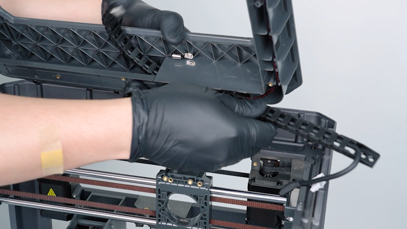
Remove the tank chain from the right side.
-
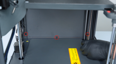
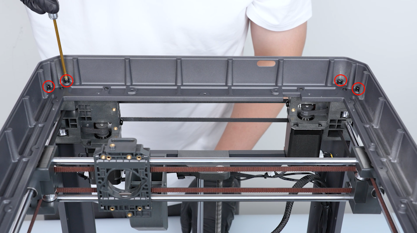
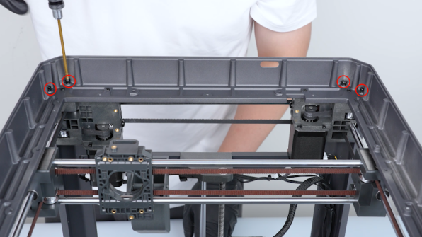
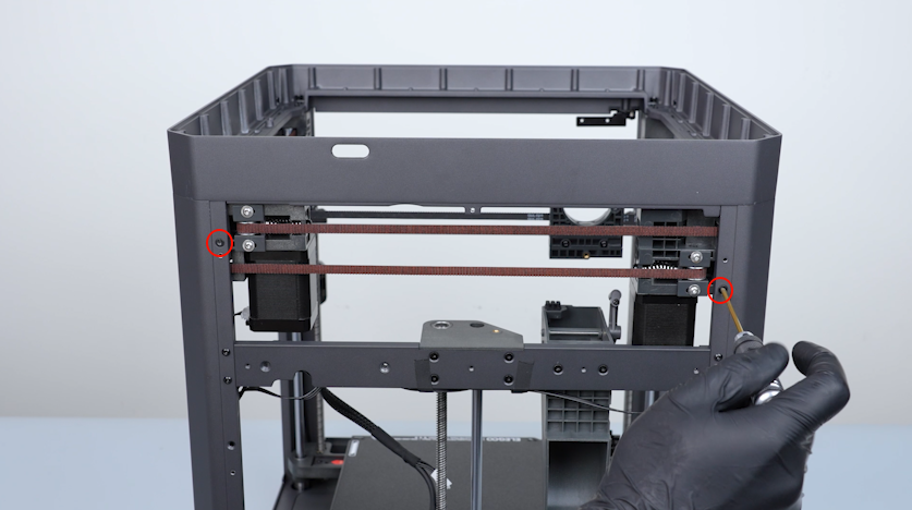
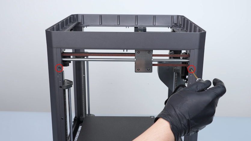
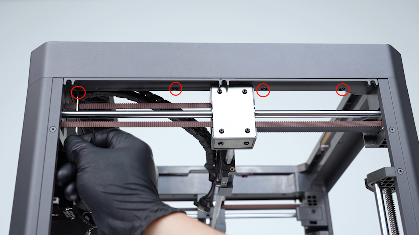
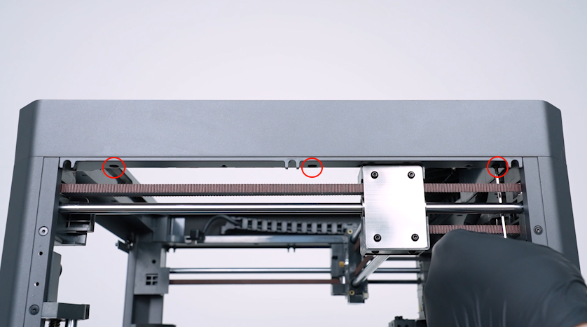
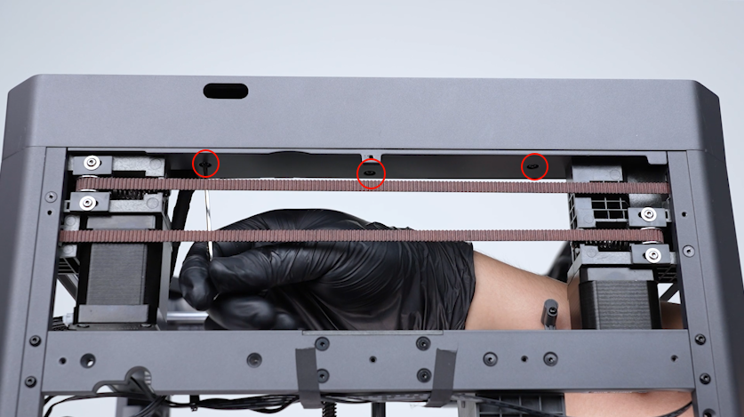
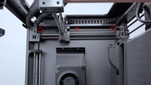
Release and remove the eight screws securing the upper frame with a 3.0 mm Allen key.
-
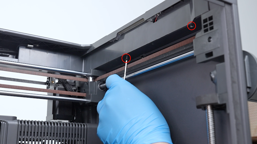
Release and remove the two screws on the back cover with a 2.0 mm Allen key.
-
Release and remove the two screws on the right cover with a 2.0 mm Allen key.
-
Release and remove the two screws on the left cover with a 2.0 mm Allen key.
-
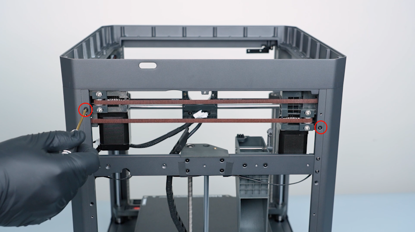
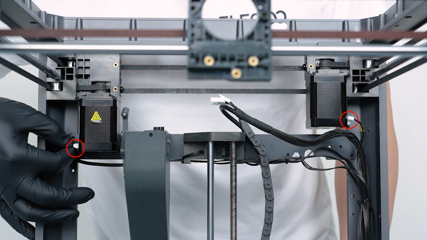
Unplug the cables of the X-axis motor and the Y-axis motor.
-
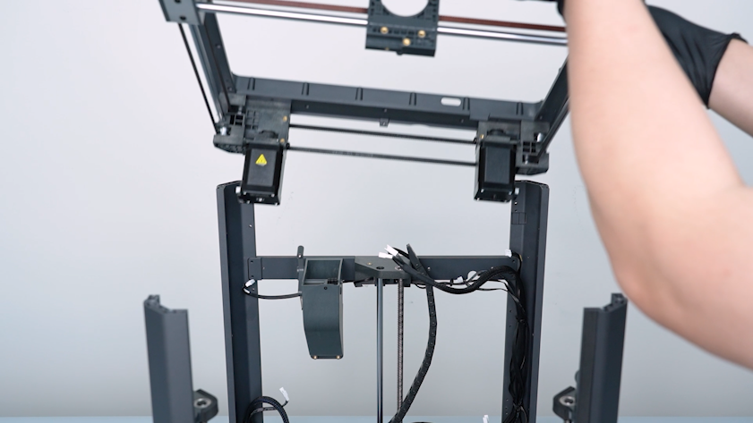
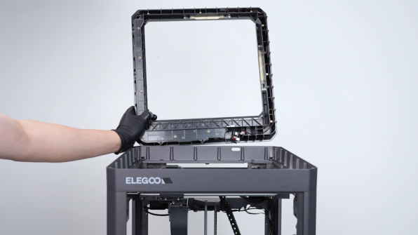
Lift the upper frame from the front door side.
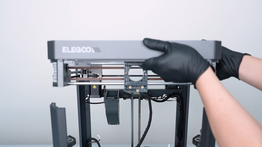
-
Remove the upper frame.
¶ Remove the slider board and the timing belt
-
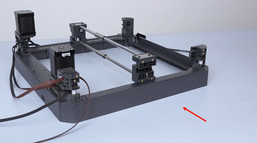
Turn the upper frame over and put it on the table.
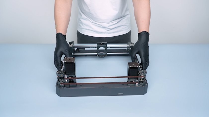
-
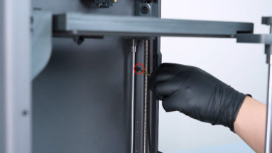
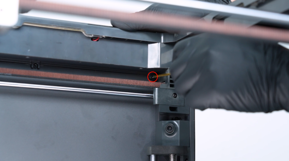
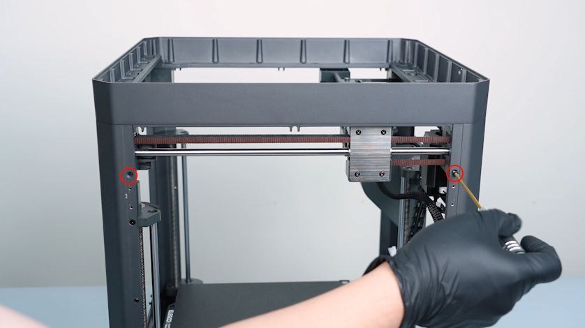
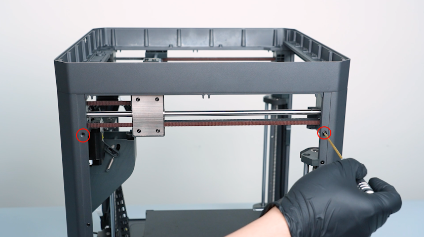
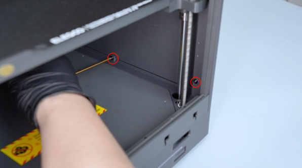
Release and remove the two screws securing the tensioner with a 2.0 mm Allen key.
-
Remove the spring and the tensioner.
-
Remove the spring and tensioner on the right side in the same way.
-
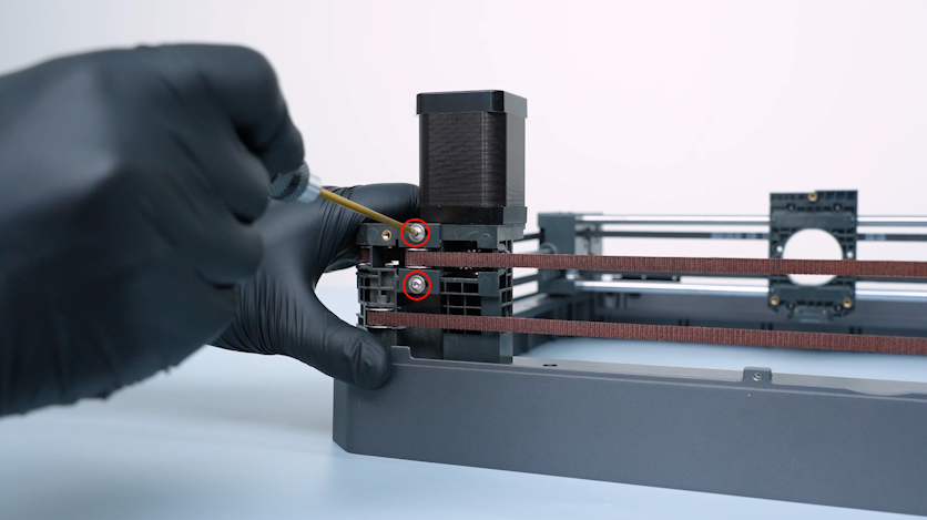
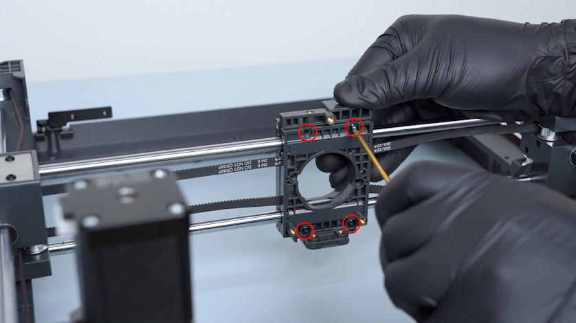
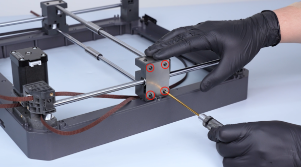
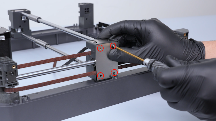
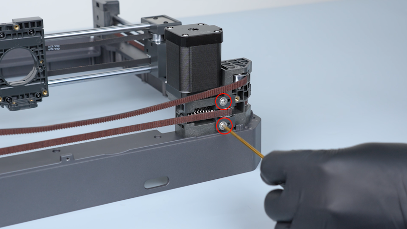
Release and remove the four screws securing the slider board with a 2.0 mm Allen key.
-
Remove the slider board.
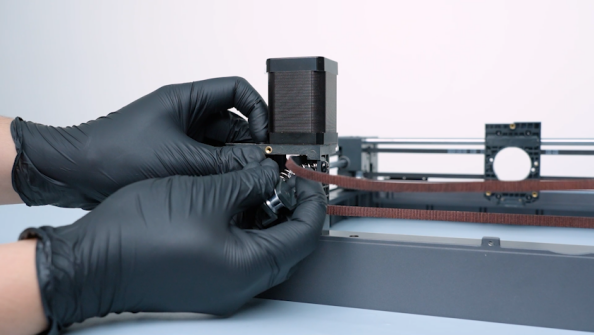
-
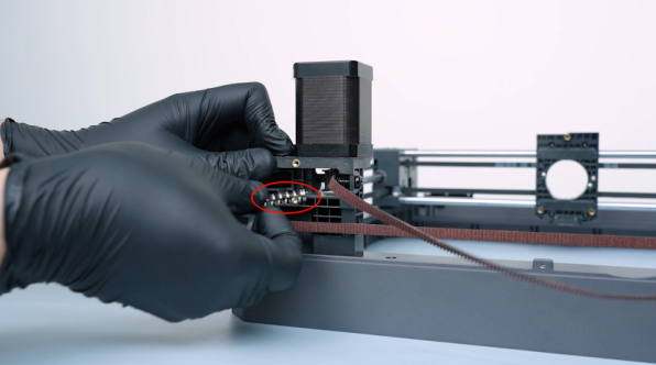
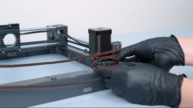
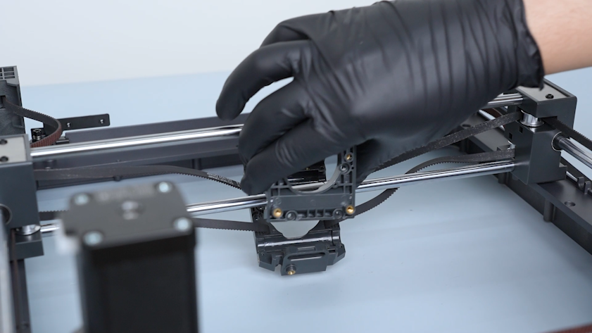
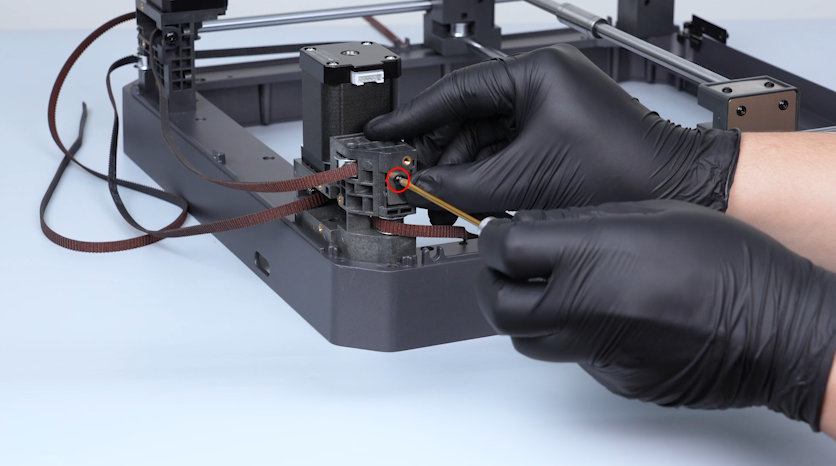
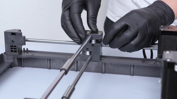
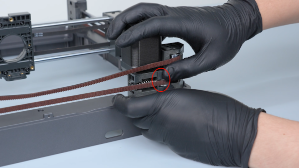
Remove the end of the timing belt with a pair of pincers. Remove fixation plates of the timing belt and keep it at hand as it will be reused later.
-
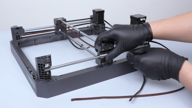
Pull the timing belt out.
¶ Replace the Y-axis rods and the bearings
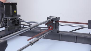
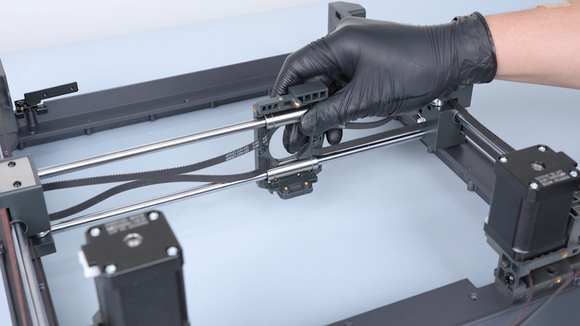
¶ Remove the old Y-axis rods and the bearings
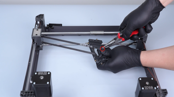
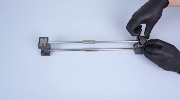
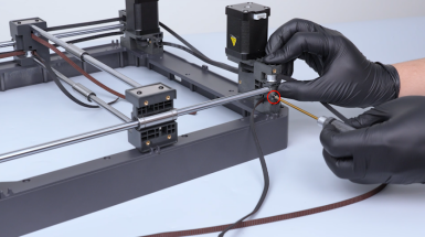
-
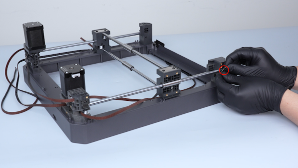
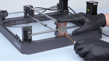
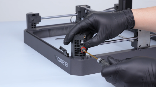
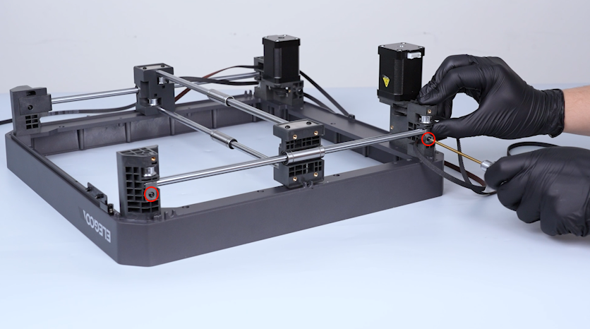
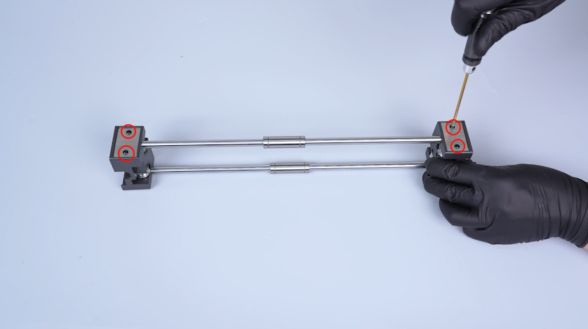
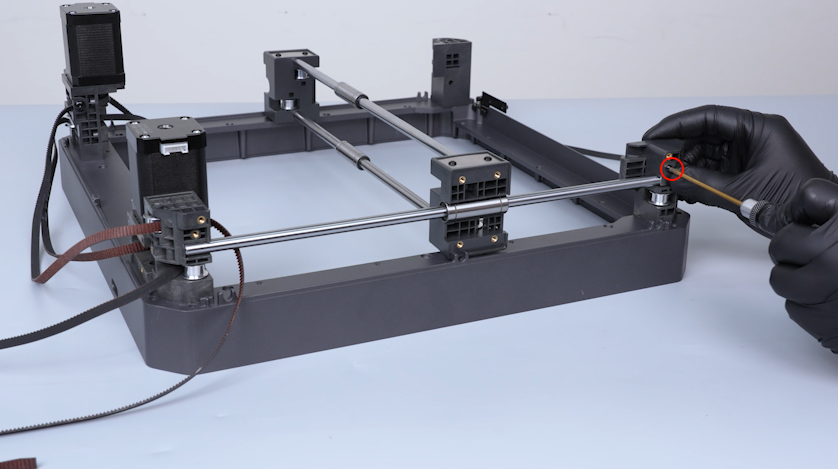
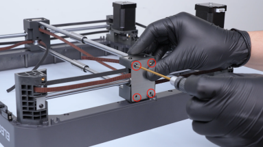
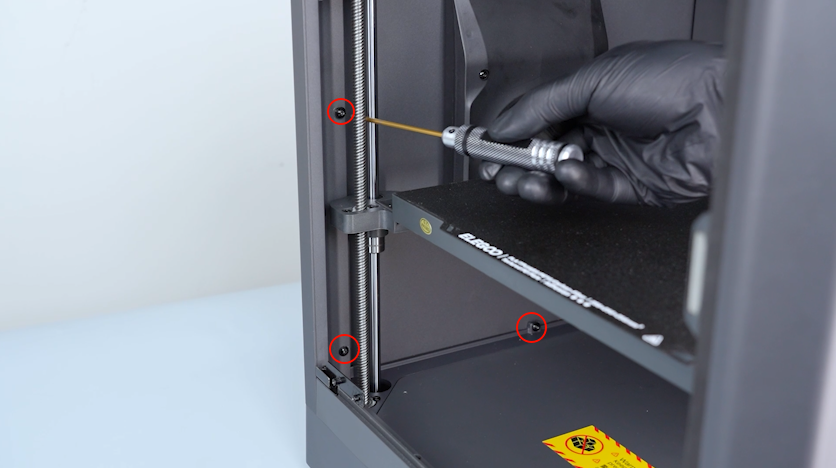
Release and remove the four screws securing the fixation board of the rod with a 2.0 mm Allen key. Remove the fixation board of the rod.
-
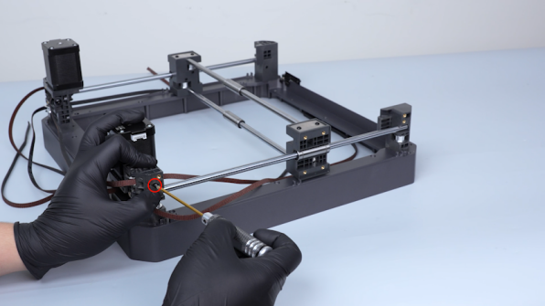
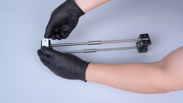
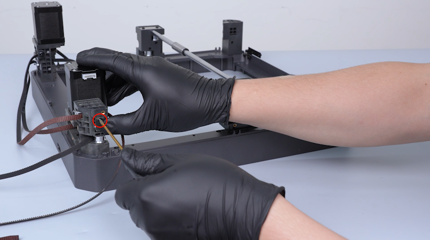
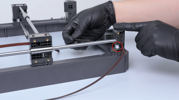
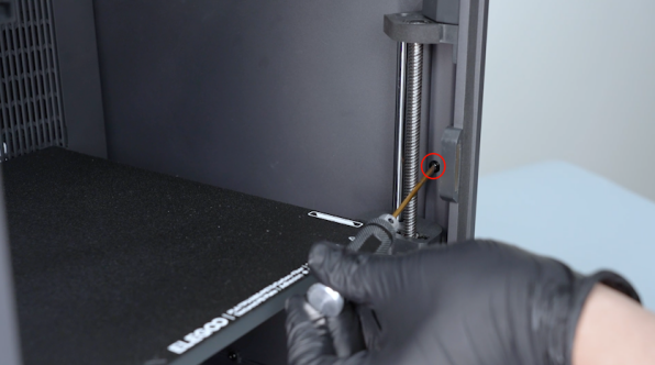
Release and remove the screw securing the Y-axis fixation plate of the rod with a 2.0 mm Allen key. Remove the Y-axis fixation plate.
-
Remove the Y-axis fixation plate of the rod on the other side in the same way.
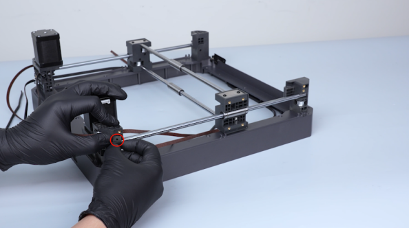
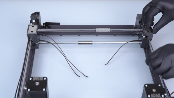
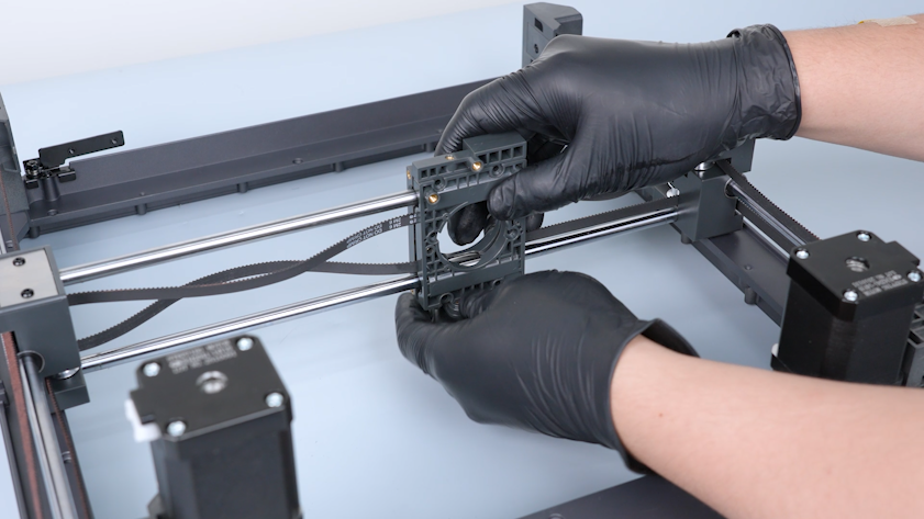
-
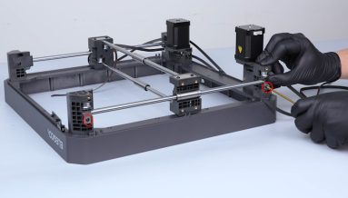
Remove the Y-axis rod and the Y-axis bearing.
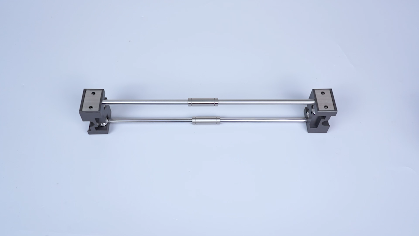
¶ Install the new Y-axis rods and bearings
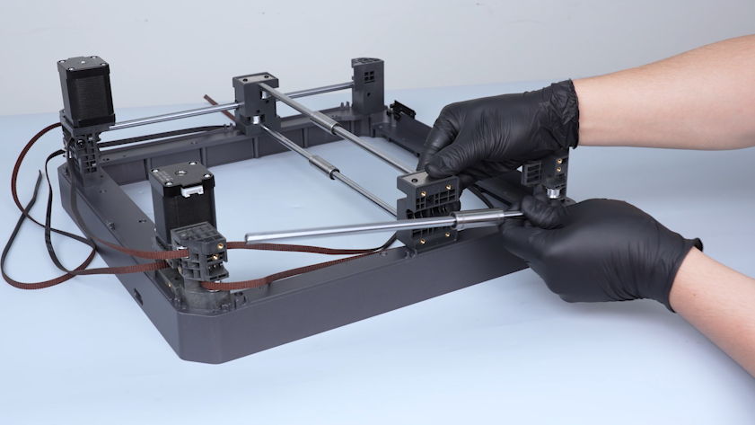
-
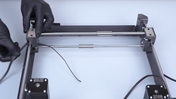
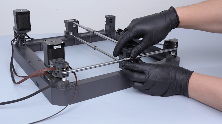
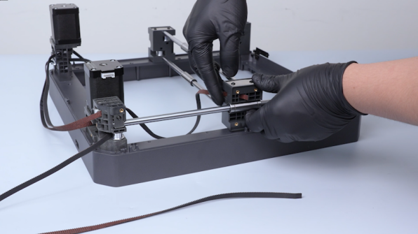
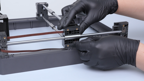
Get the new Y-axis rod and the new Y-axis bearing. Put the Y-axis rod and the Y-axis bearing in the installation position.
-
Put the fixation board of the rod in the installation position.
-
Tighten the four screws securing the fixation board.
-
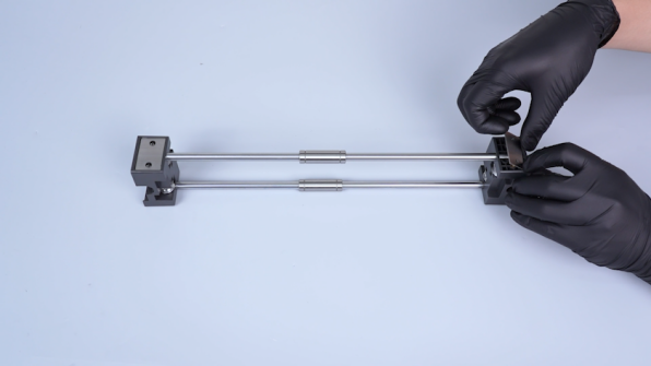
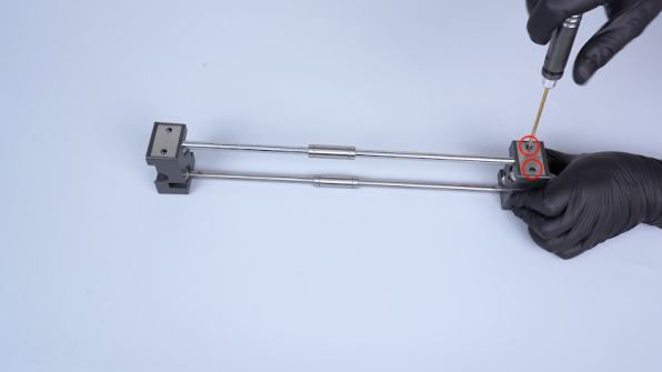
Put the fixation Y-axis rod fixation plate in the installation position and tighten the screw.
-
Install the Y-axis fixation plate of the rod on the other side in the same way.
-
Remove and install the Y-axis fixation board of the rod and the fixation plates on the other side in the same way.
¶ Replace the X-axis rods and the bearings
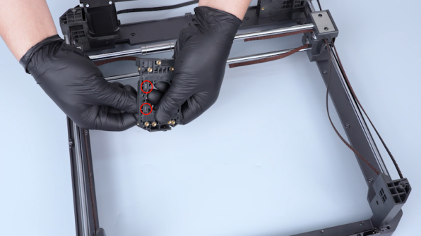
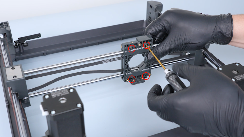
¶ Remove the old X-axis rods and the bearings
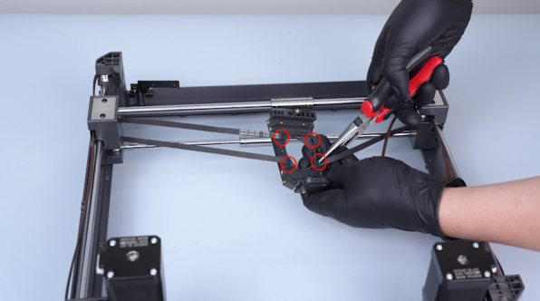
-
Release and remove the four screws securing the fixation board of the rod with a 2.0 mm Allen key. Remove the fixation board.
-
Release and remove the screws securing the Y-axis fixation plates of the rod with a 2.0 mm Allen key. Remove the Y-axis fixation plates.
-
Remove the Y-axis rod and the bearing.
-
Remove the Y-axis fixation board on the other side in the same way.
-
Remove the Y-axis fixation plates and the Y-axis rod and the bearing on the other side in the same way.
-
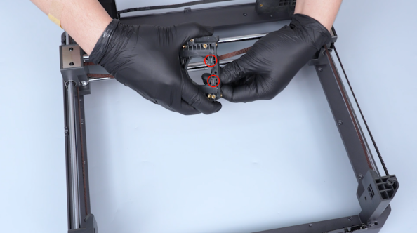
Remove the X axis and place it on the table.
-
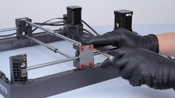
Release and remove the four screws securing the fixation board of the X-axis rod with a 2.0 mm Allen key.
-
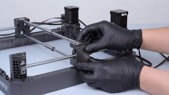
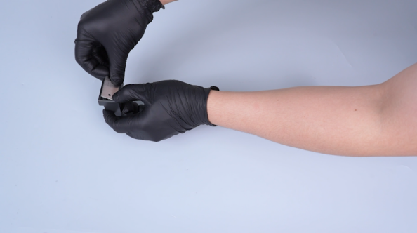
Remove the fixation boards.
-
Remove the fixation board of the X-axis rod on the other side in the same way.
-
Remove the X-axis rods and the bearings.
¶ Install the new X-axis rods and the bearings
-
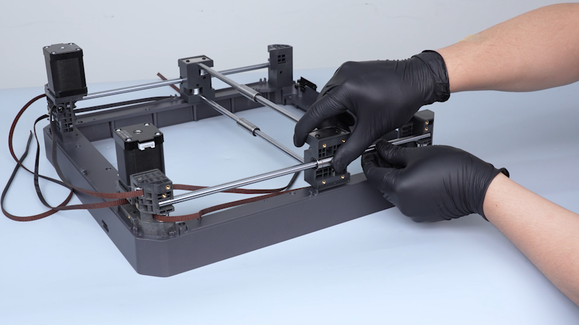
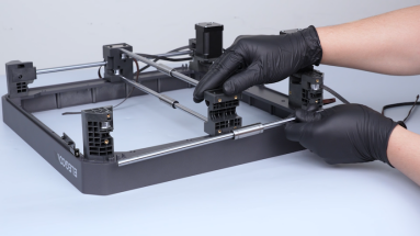
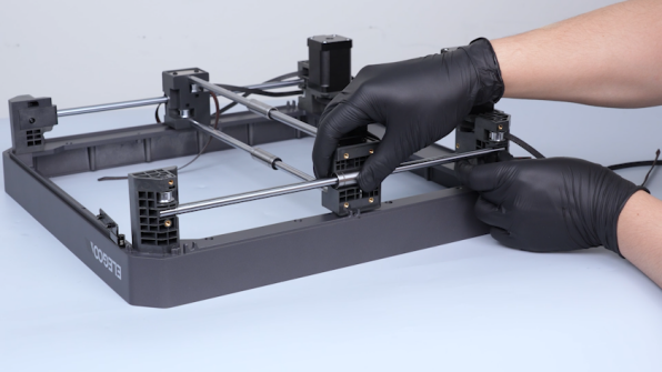
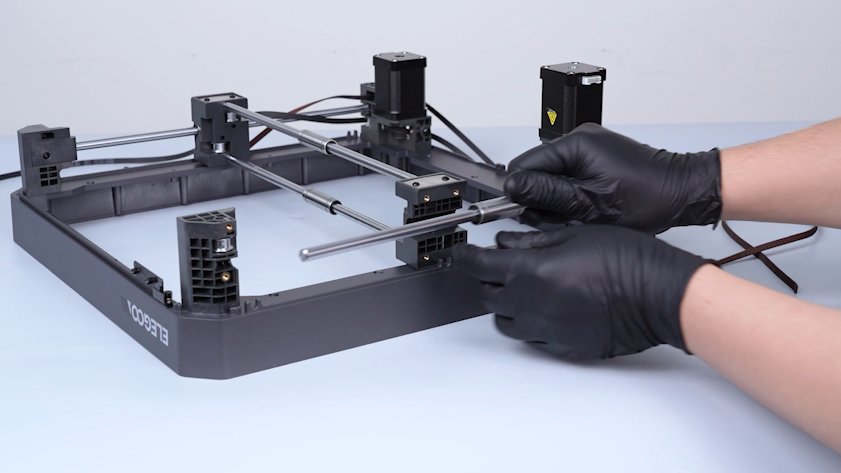
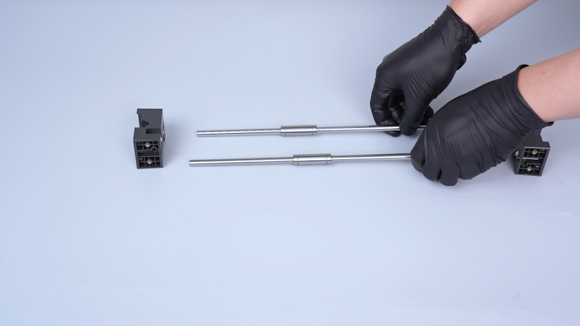
Put the new X-axis rods and the new X-axis bearings in the installation position.
-
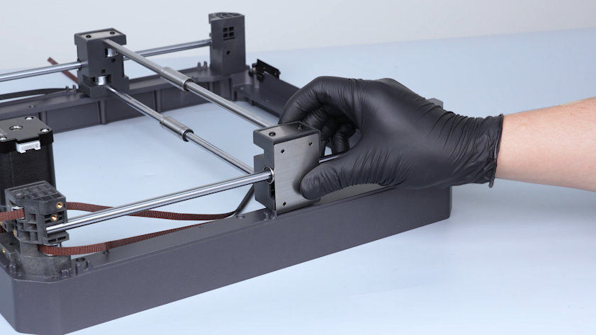
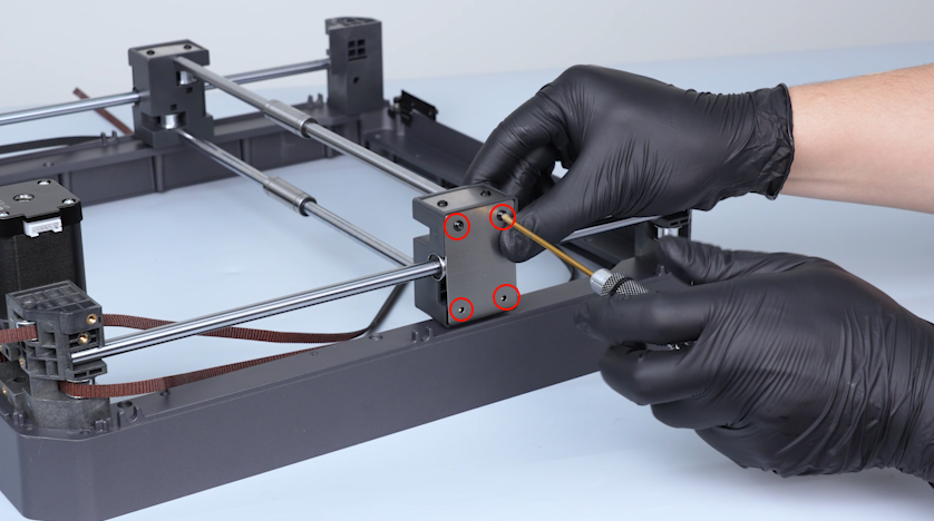
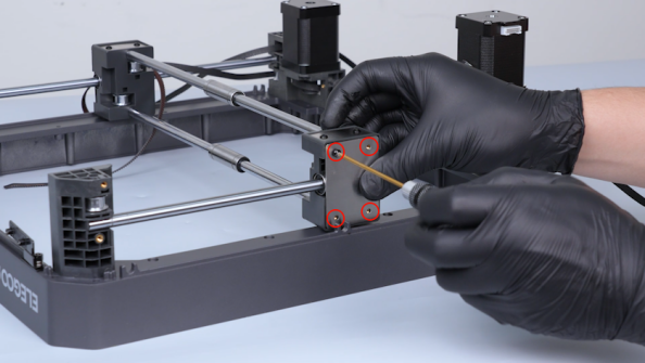
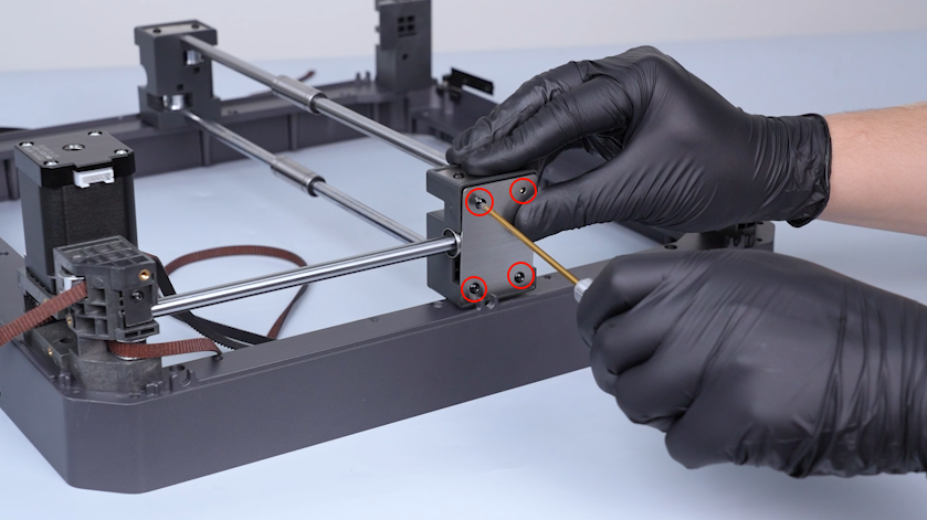
Put the fixation plates of the X-axis rods in the installation position and tighten the four screws.
-
Install the fixation plates of the X-axis rods on the other side in the same way.
-
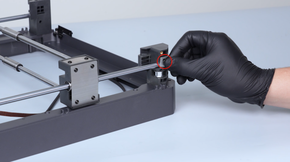
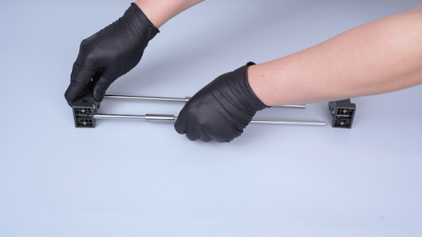
Put the X axis in the installation position.
Note: The left groove is on the upper side and the right groove is on the lower side.
-
Move the upper frame and face the Y-axis fixation board installation position.
-
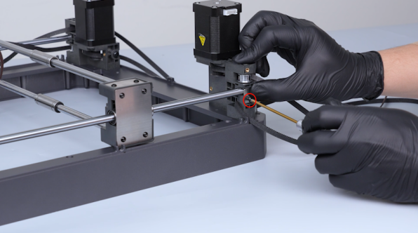
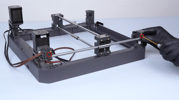
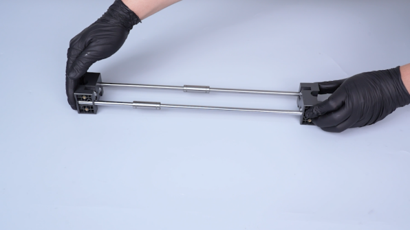
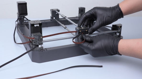
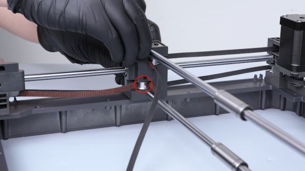
Place the Y-axis rod and the bearing in the installation position.
-
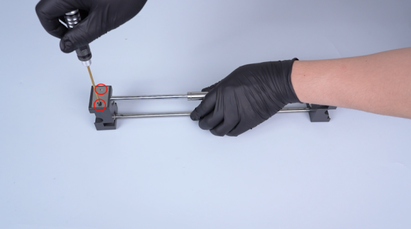
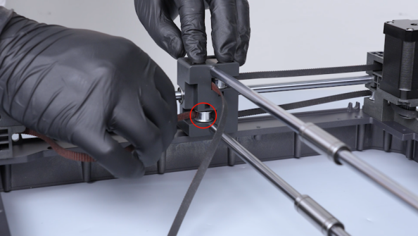
Put the fixing plate of the Y-axis rod in the installation position and tighten the screw securing the fixing plate of the Y-axis rod.
-
Install the fixation plate of the Y-axis rod on the other side in the same way.
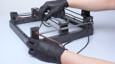
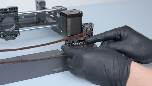
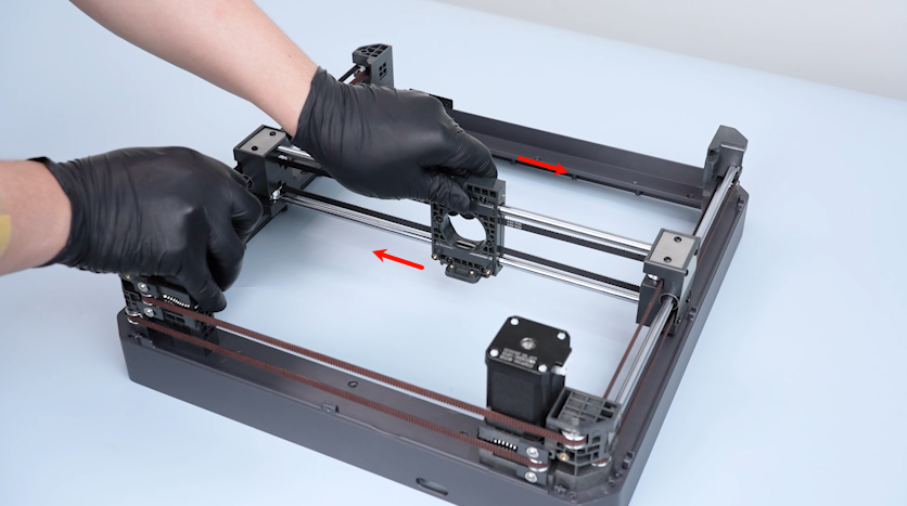
¶ Install the timing belts
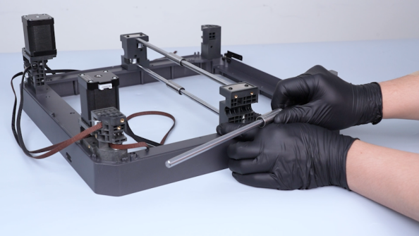
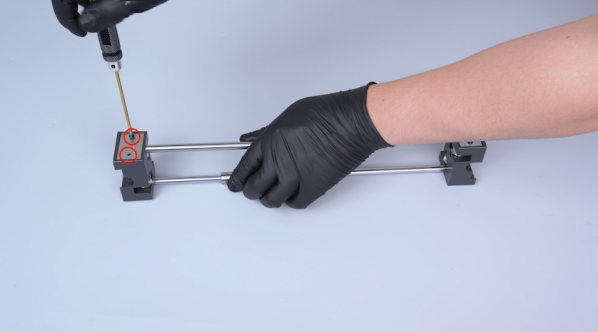
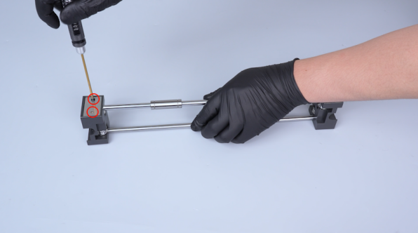
-
Pass the timing belts through the timing pulleys.
-
Tighten the four screws securing the fixation board.
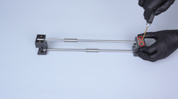
-
Install the Y-axis rod, bearing and timing belt on the other side in the same way.
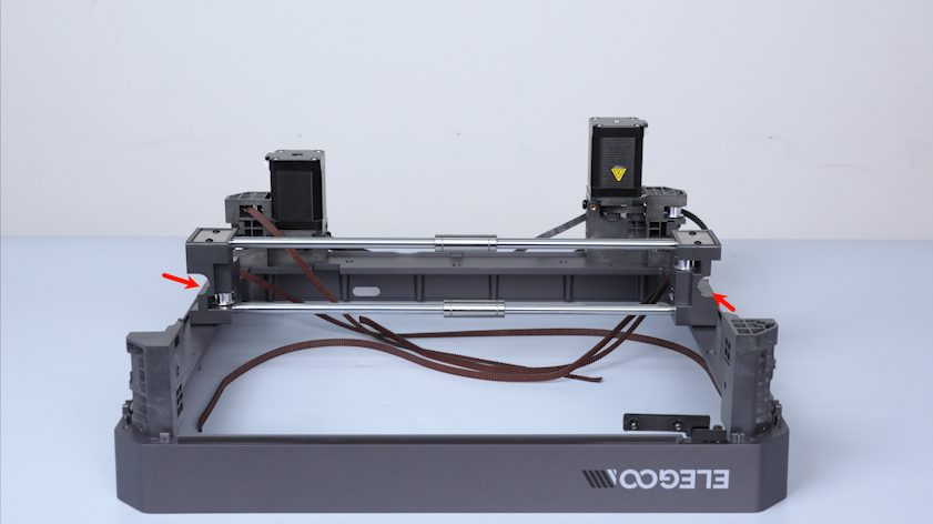
-
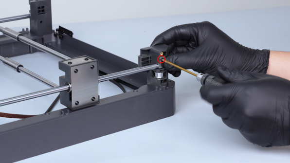
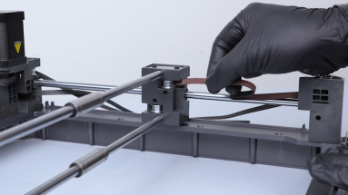
Get the back cover. Pass the end of the timing belt through the hole in the back cover and put the timing belt fixation plate in place and pull the belt tight.
-
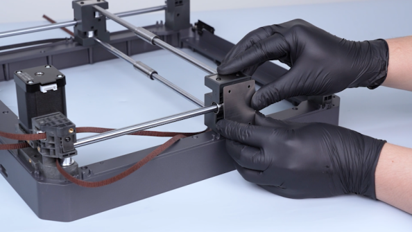
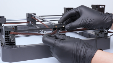
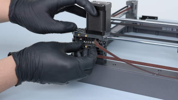
Align the slider board with the bearing and put it in the installation position.
-
Prepare the other slider board and put it in the installation position.
-
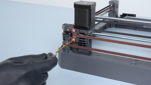
Hold the slider board. Tighten the four screws securing the slider board.
-
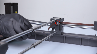
Put the springs in the installation position. Get the tensioner and put it in the installation position.
-
Press the tensioner in place. Tighten the two screws securing the tensioner.
Note: Do not tighten the screws at this time.
-
Install the tensioner on the other side in the same way.
¶ Verify the smoothness of the slider board
-
Move the slider board ro confirm that the slider board can move smoothly.
-
Tighten the four screws securing the tensioner.
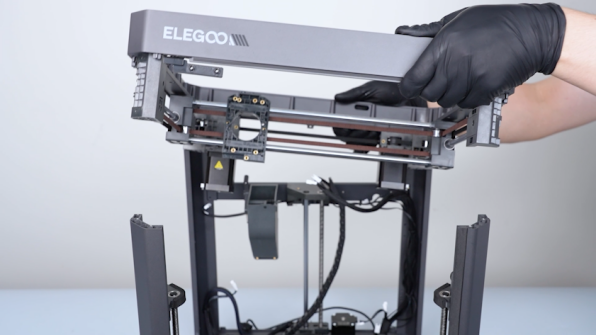
¶ Install the upper frame
-
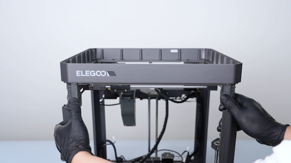
Lift the upper frame and align it with the pillars on the back side.
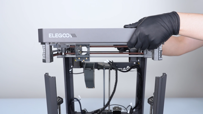
-
Install the back of the upper frame and the front side.
-
Plug in the cables of the left and right motors.
-
Tighten the eight screws securing the upper frame.
-
Tighten the two screws on the back cover.
-
Tighten the two screws on the right cover.
-
Tighten the two screws on the left cover.
-
Get the upper frame housing. Plug in the cables of the LED and the chamber thermistor.
-
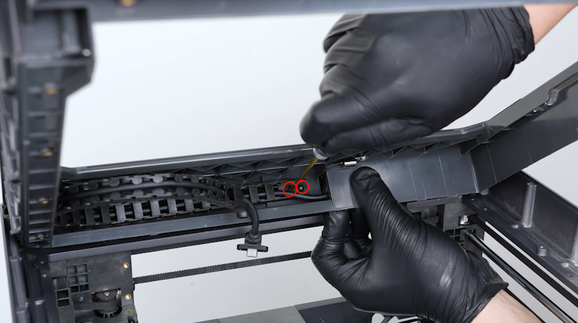
Pass the tank chain through the upper frame housing.
-
Tighten the two screws securing the tank chain.
-
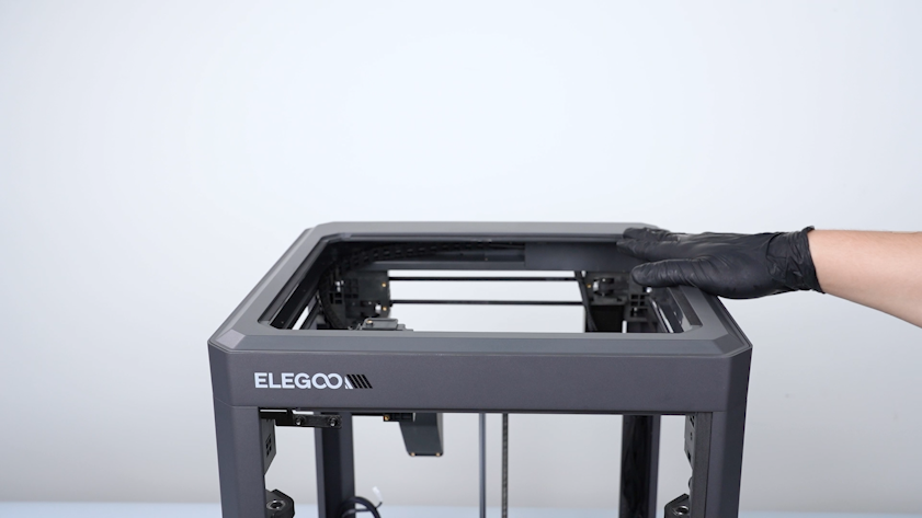
Install the upper frame housing.
-
Tighten the three screws securing the front side of the upper frame housing.
-
Tighten the four screws securing the left side of the upper frame housing.
-
Tighten the three screws securing the right side of the upper frame housing.
-
Tighten the three screws securing the back side of theupper frame housing.
¶ Install the partition, left cover and right cover
-
Get the partition and put it in the installation position.
Note: Do not tighten the screws securing the partition at this time.
-
Get the left cover. Put the left cover in the installation position.
-
Plug in the auxiliary cooling fan cable.
-
Tighten the eight screws securing the left cover.
-
Before tightening the screws on the bottom, pull the Z-axis timing belt to raise the heated bed to the middle of the printer.
-
Tighten the screws.
-
Get the right cover. Tighten the eight screws securing the right cover.

-
Plug in the servomotor detection board cable and the chamber cooling fan cable.
-
Tighten the screw securing the upper side of the partition.
-
Tighten the six screws securing the back side of the partition.
-
Tighten the two screws securing the bottom of the partition.
-
Get the touch screen. Put the touch screen in the installation position.
-
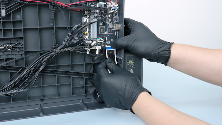
Plug in the ribbon cable of the touch screen into the port on the motherboard. Press the clip.
-
Get the tape and adhere it on the port.
¶ Install the back cover and the bottom cover
-
Get the bottom cover. Put the bottom cover in the installation position.
-
Tighten the ten screws securing the bottom cover.
-
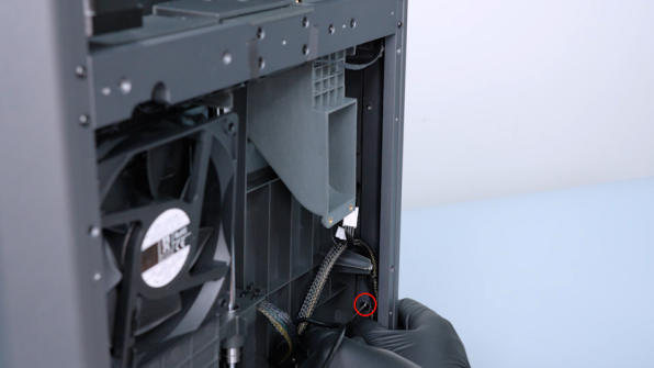
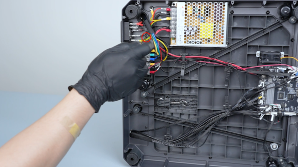
Get the back cover. Tighten the two screws securing the CANVAS extension cable.
-
Lift the back cover. Put the CANVAS extension cable into the gap besides the chamber cooling fan.
-
Close the back cover.
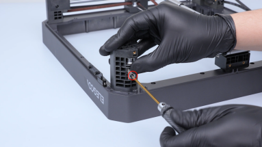
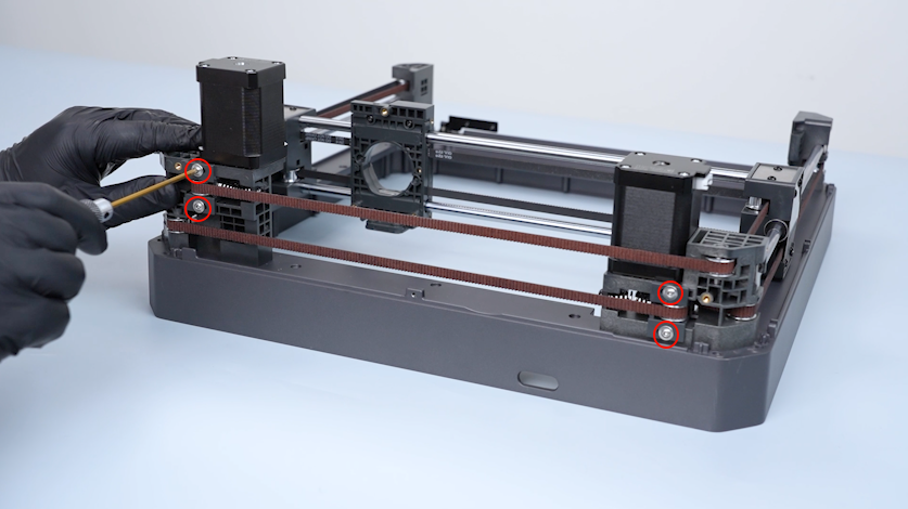
-
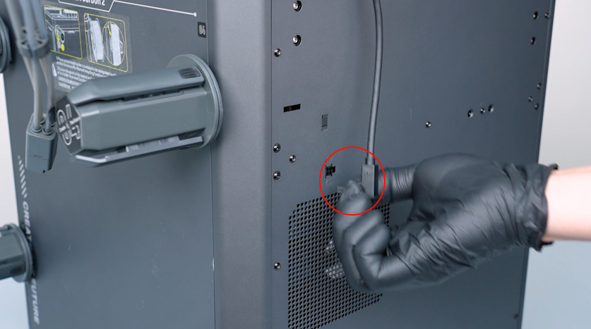
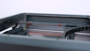
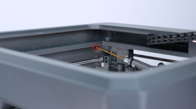
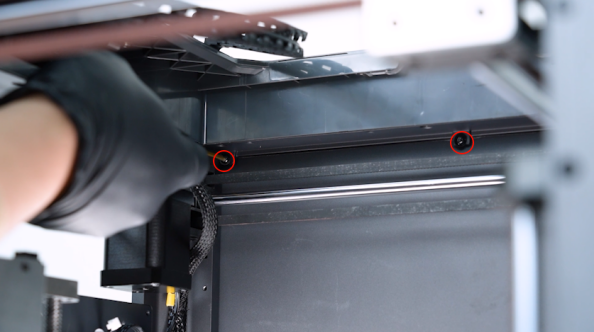
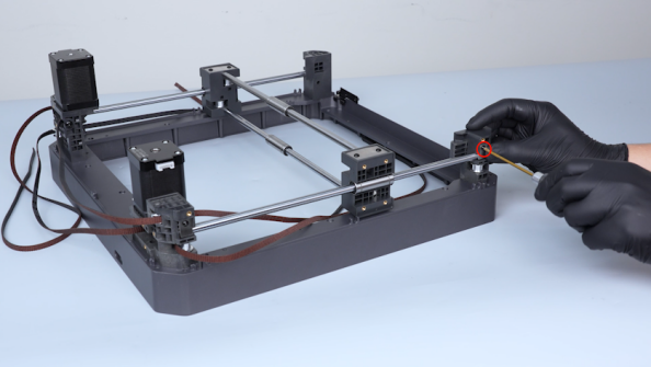
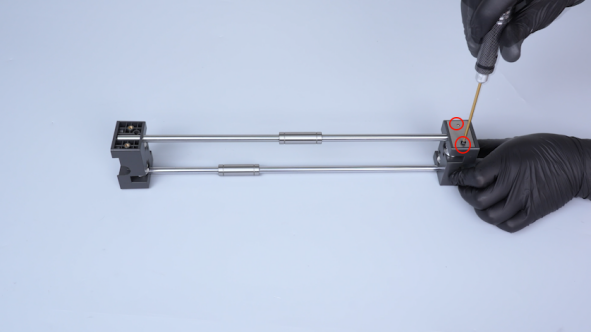
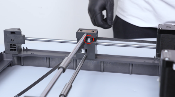
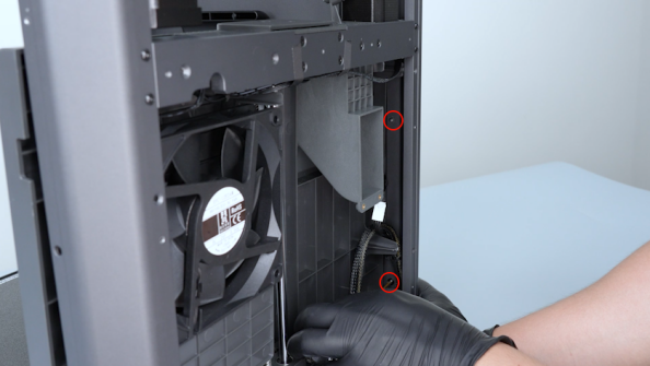
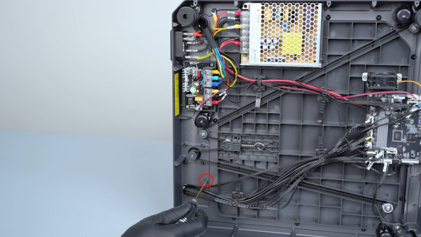
Tighten the sixteen screws securing the back cover.
Note: Screws labeled by the red circle are M3 x 4. Screws labeled by the yellow circle are M3 x 8.
¶ Install the gearbox assembly
-
Get the E motor.
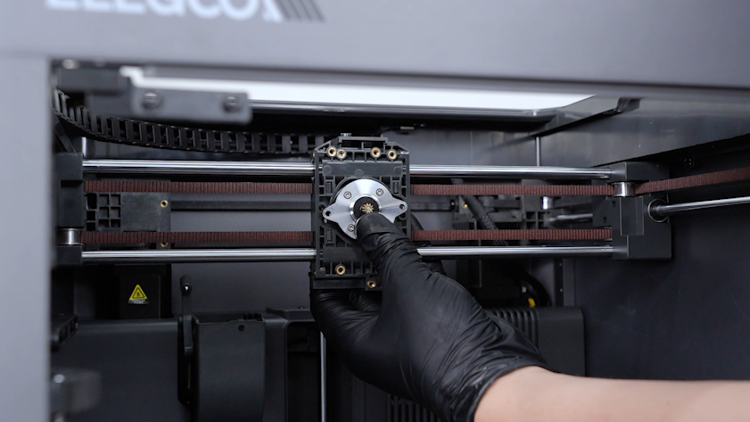
-
Put the E motor in the installation position. Tighten the two screws securing the E motor.
-
Get the communication board. Tighten the three screws securing the communication board.
-
Plug in the E motor cable and the cables of the communication board and the model cooling fan.
-
Organize the cables. Put the cable into the groove of the slider board.
-
Install the tool head board.
-
Tighten the screw securing the tool head board.
-
Get the back cover and put it in the installation position. Tighten the three screws securing the back cover of the tool head.
-
Get the gearbox and put it in the installation position.
-
Tighten the two screws securing the gearbox.
¶ Install the 4-in-1 hub holder and the tool head
-
Get the 4-in-1 hub holder and put it in the installation position. Tighten the two screws.
-
Plug in the heat break cooling fan cable. Tighten the screw securing the fan.
-
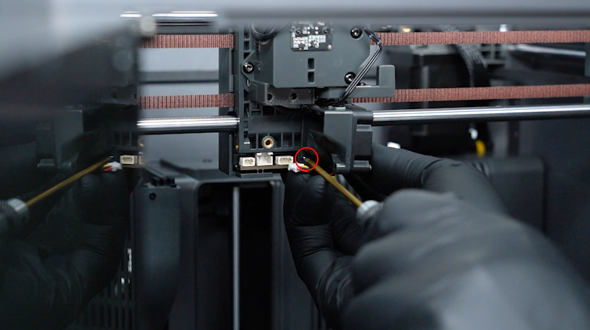
Plug in the cables of the ceramic heating plate and the hotend thermistor.
-
Tighten the two screws securing the hotend.
-
Plug in the communication board adapter cable and the cutter detection board cable into the ports on the filament detection board.
-
Put the tool head housing in the installation position.
-
Tighten the four screws securing the tool head housing with a 2.0 mm Allen key.

-
Get the model cooling fan. Plug in the model cooling fan cable.
-
Install the front cover of the tool head.
¶ Install the 4-in-1 hub, CANVAS and the CANVAS holder
-
Get the CANVAS holder and put it in the installation position. Tighten the two screws with a 2.0 mm Allen key.
-
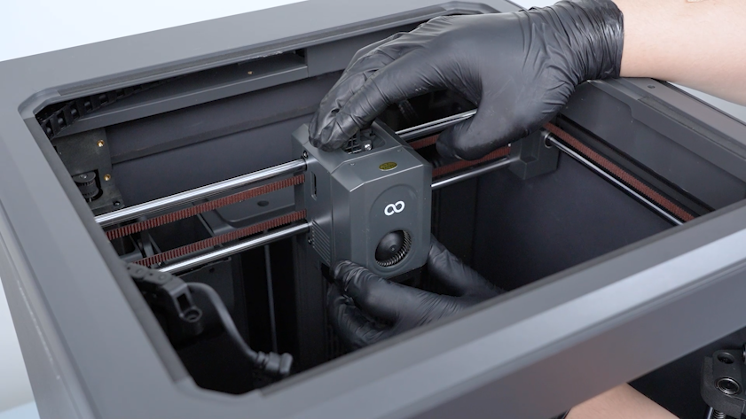
Get the CANVAS and put it in the installation position.
-
Tighten the three screws.
-
Plug in the communication cable of CANVAS.
-
Install the 4-in-1 hub onto the tool head. Tighten the two screws.
-
Tighten the two screws securing the CAN bus.
-
Tighten the screw securing the tank chain.
-
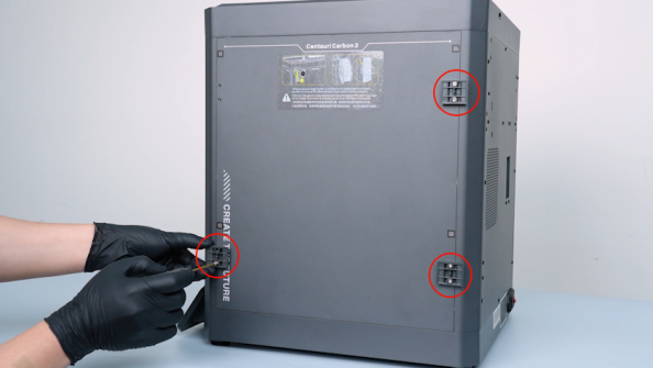
Get the spool holder pallet. Tighten the two screws securing the spool holder pallet.
-
Install the other spool holder pallets in the same way.
-
Install the spool holders.
-
Get the front door and put it in the installation position.
-
Install the silicone stoppers and tighten the screws.
¶ Verification
-
Plug in the power supply cable. Turn the power switch ON (symbol "|") .
-
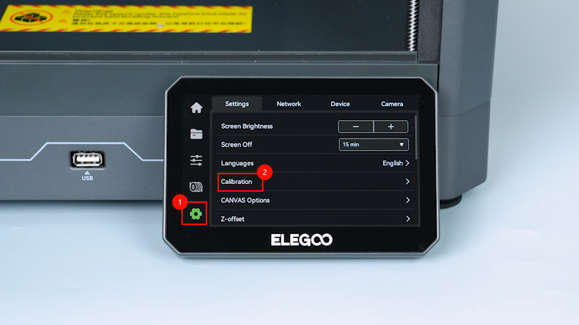
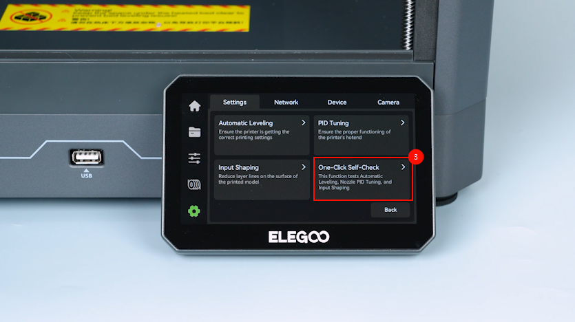
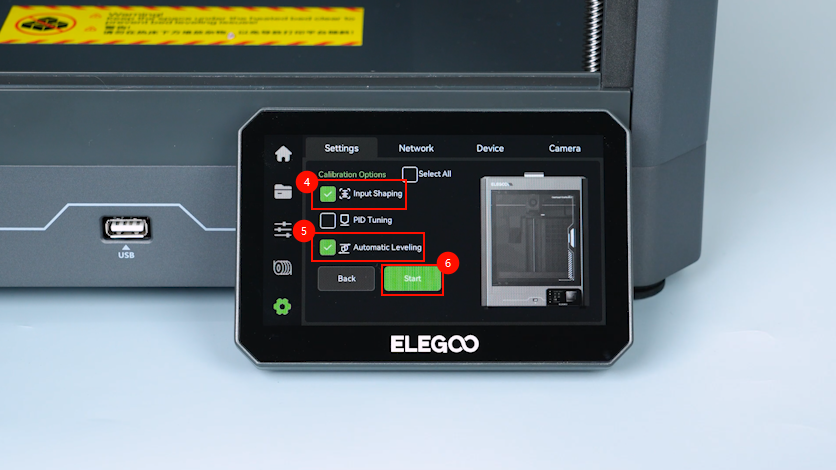
On the touchscreen, select Settings - Calibrate - One-click Self-check - Input Shaping - Auto Levelling.
-
The printer is then ready for use after the calibration.
¶ Help us improve
If you have any ideas about the wiki pages, please let us know via ELEGOO official feedback channel