¶ Operation Steps for Each Model
The steps below are based on Centauri Carbon 2 Combo. For other models, skip the steps related to parts that are not installed.
| Model | Action | Steps to Skip |
|---|---|---|
| Centauri Carbon 2 Combo | Follow all steps | None |
| Centauri Carbon 2 | Skip enclosure and CANVAS-related steps |
|
| Centauri 2 Combo | Skip enclosure-related steps only if the enclosure is not installed |
|
| Centauri 2 | Skip enclosure and CANVAS-related steps |
|
If your printer has optional accessories installed, such as CANVAS or an enclosure, follow the steps related to those parts.
¶ Tools and Materials
-
A 2.0 mm Allen key
-
A pair of tweezers
-
A pair of pliers
-
A new upper frame board
¶ Instruction
¶ Preparation
-
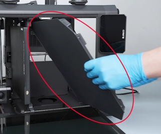
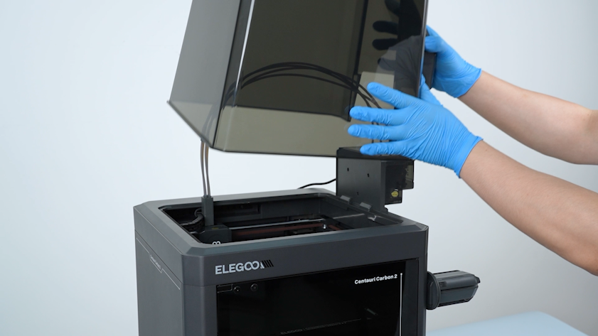
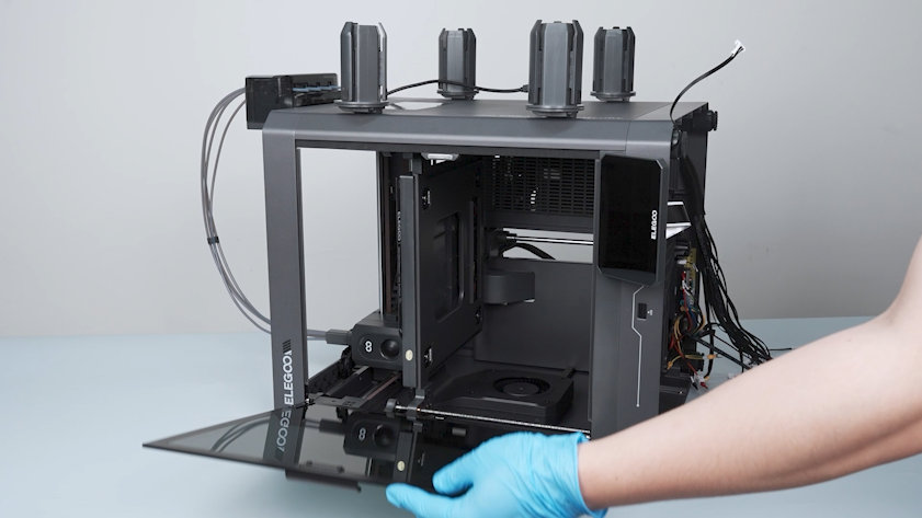
Remove the lid.
-
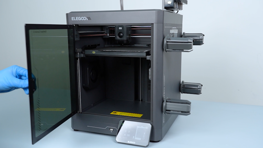
Plug in the power supply cable and turn the power switch ON (symbol "|").
-
Open the front door.
-
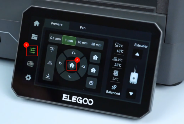
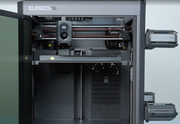
On the touch screen, select Control - Homing. Wait for the homing process of the tool head to complete.
-
Turn the power switch OFF (symbol "〇") and unplug the power supply cable.
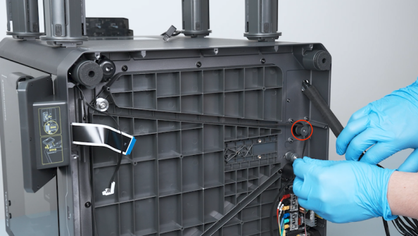
¶ Remove the back cover, partition and bottom cover
-
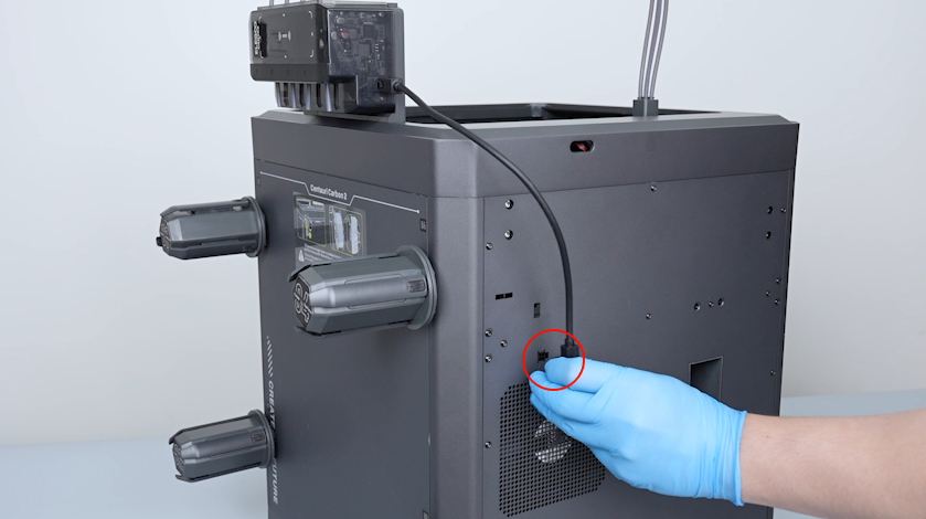
Unplug the CANVAS communication cable.
-
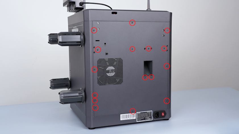
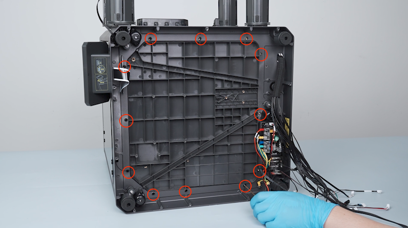
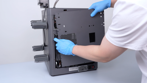
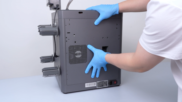
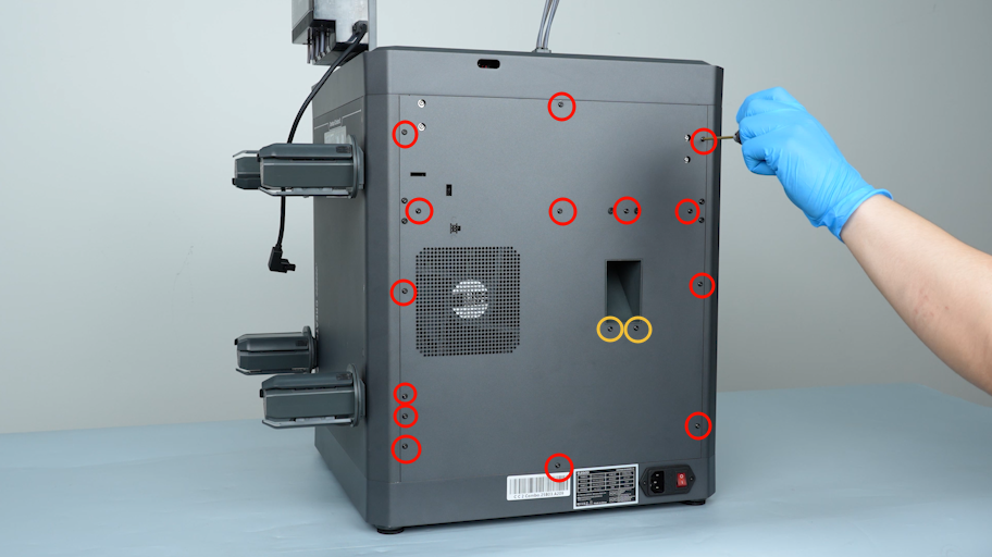
Release and remove the sixteen screws securing the back cover with a 2.0 mm Allen key.
-
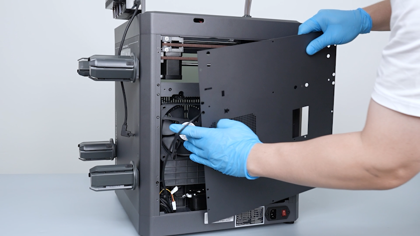
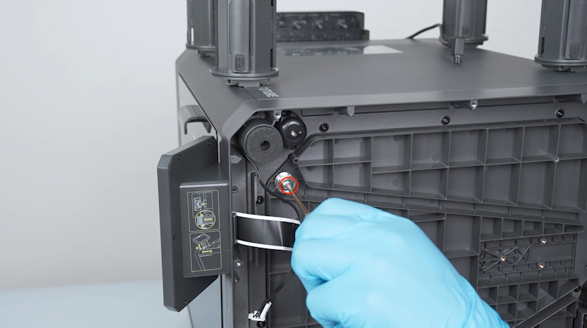
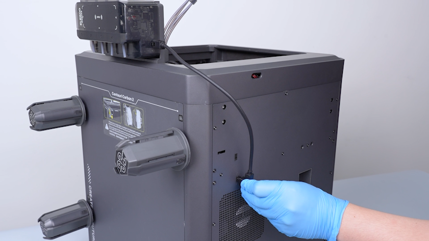
Remove the CANVAS extension cable from the gap on the chamber cooling fan side.
-
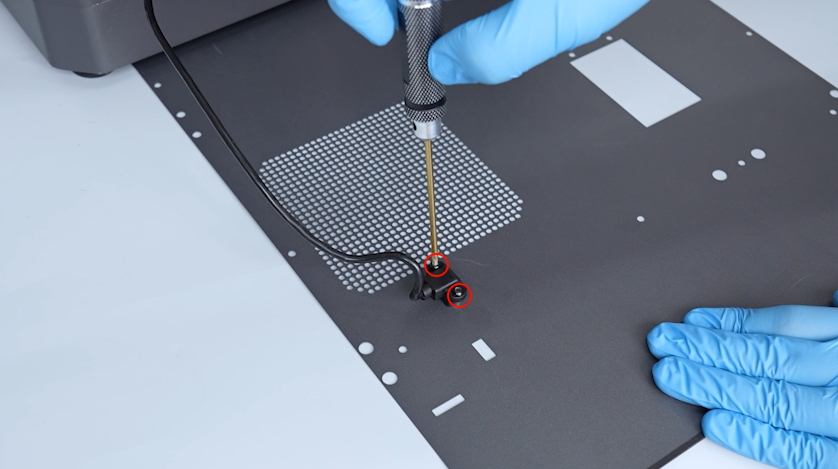
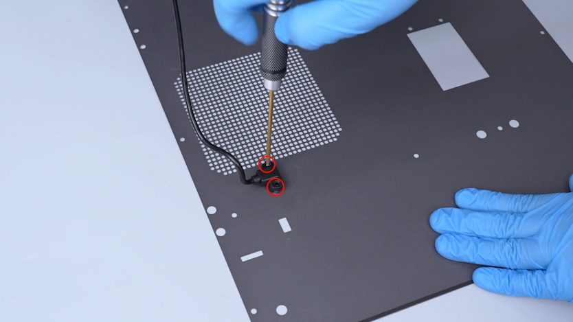
Release and remove the two screws securing the CANVAS extension cable with a 2.0 mm Allen key.
-
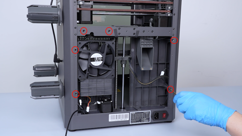
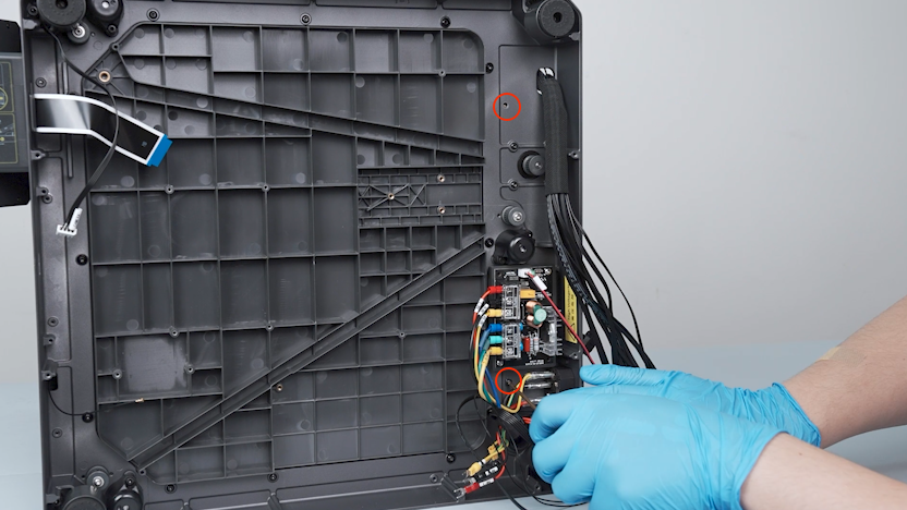
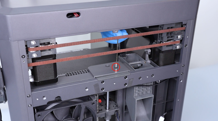
Release and remove the screw on the partition with a 2.0 mm Allen key.
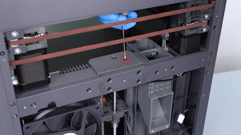
-
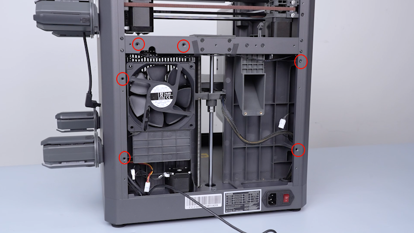
Release and remove the six screws on the back side of the partition with a 2.0 mm Allen key.
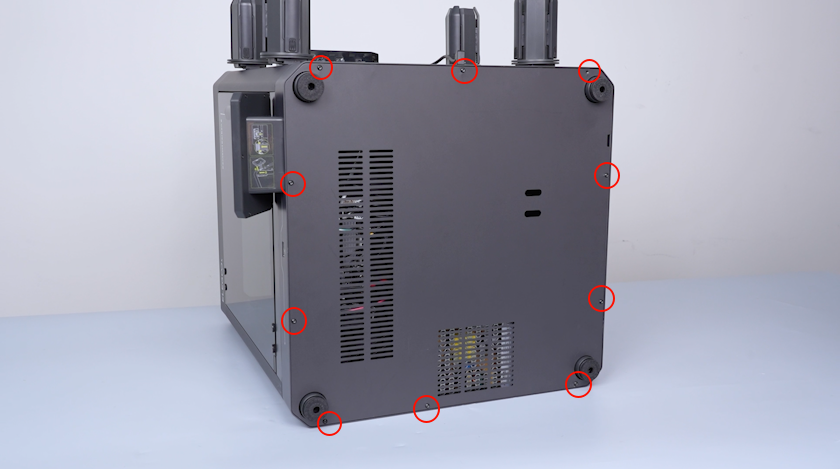
-
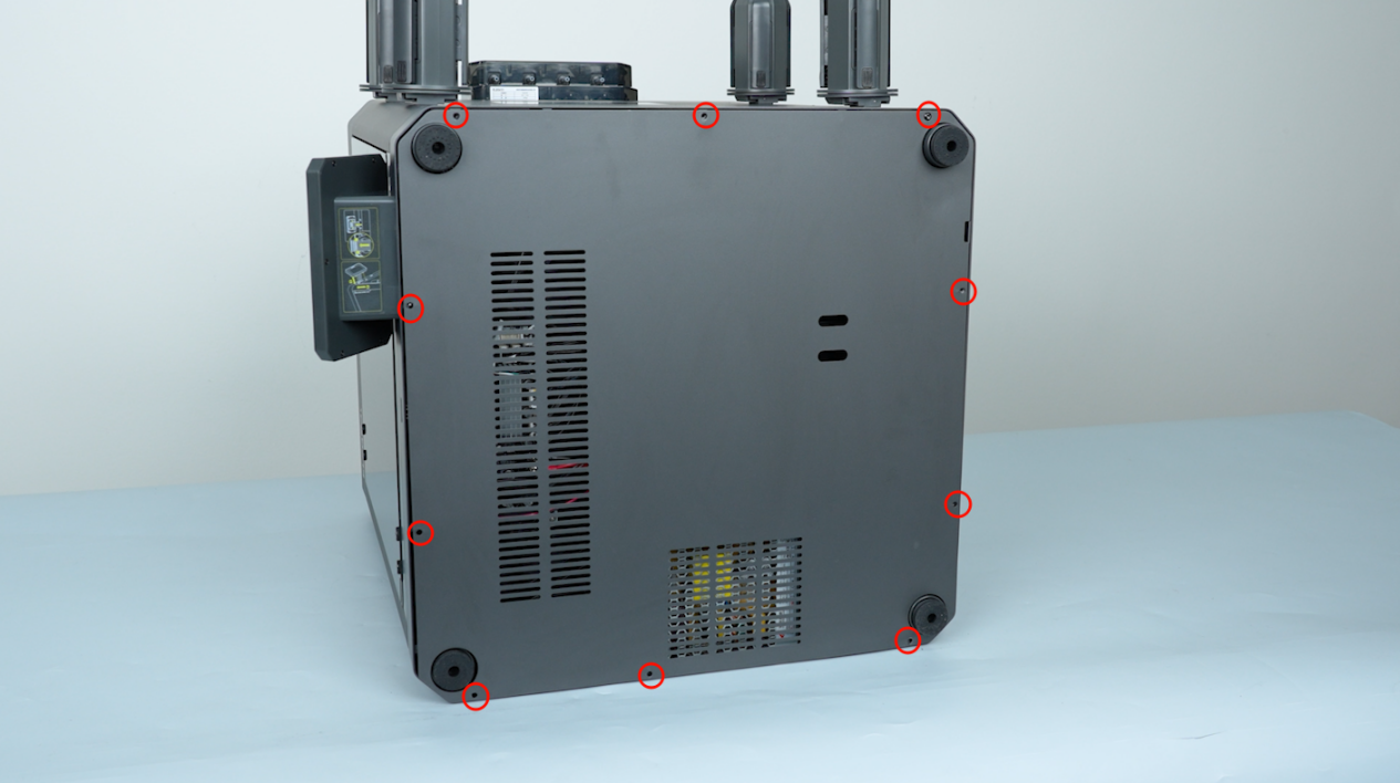
Release and remove the ten screws securing the bottom cover with a 2.0 mm Allen key and remove the bottom cover.
¶ Remove the motherboard and the motherboard cooling fan
-
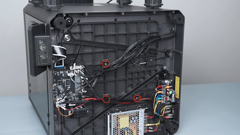
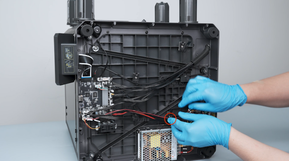
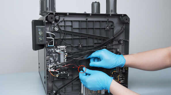
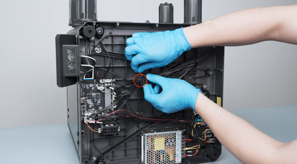
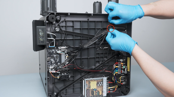
Loosen the four cable ties securing the power wires.
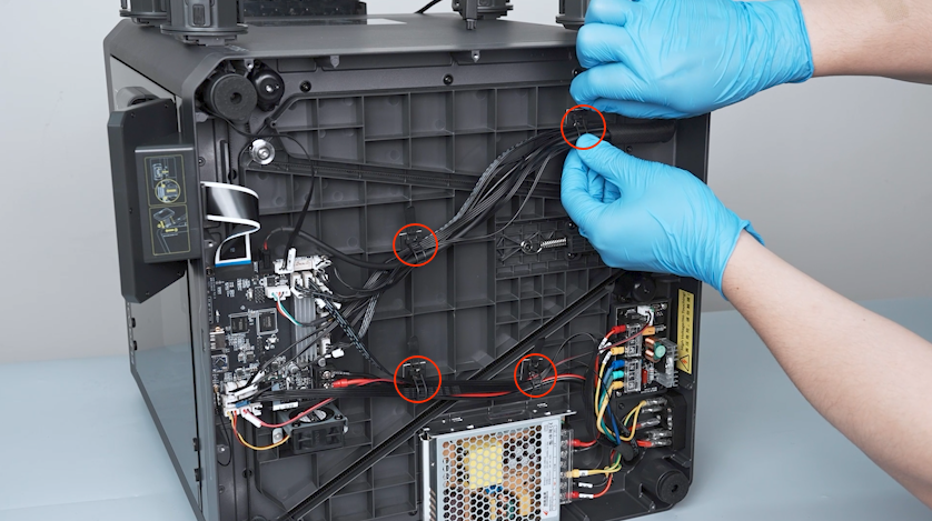
-
Release and remove the screw securing the cable tie with a 2.0 mm Allen key and remove the cable tie.
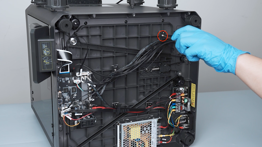
-
Remove the other three cable ties in the same way.
-
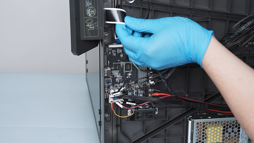
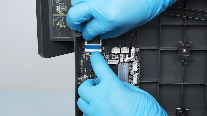
Remove the tape securing the touch screen ribbon cable.
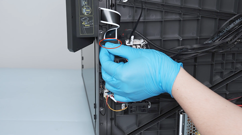
-
Lift the clip of the touch screen cable port on the motherboard.
-
Unplug the touch screen ribbon cable.
Note: The cable connected to the motherboard has a clip. If it cannot be easily removed, use a pair of tweezers to lift the clip and try to remove the clip again. Unplugging the cable forcibly without lifting the clip may damage the port on the motherboard.
-
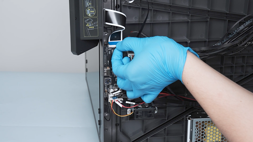
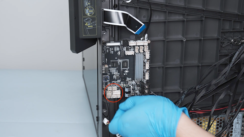
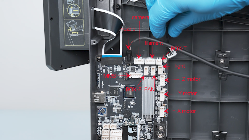
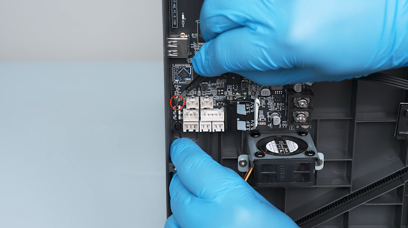
Remove the plugs on the upper and right sides of the motherboard.
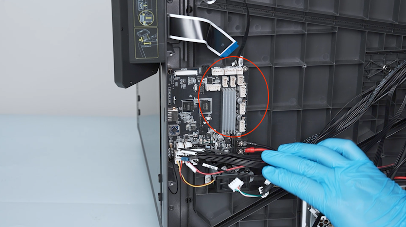
-
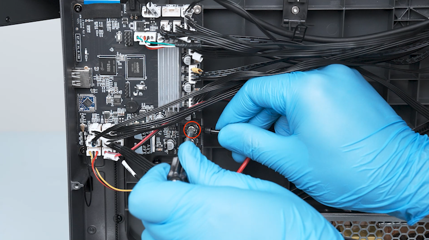
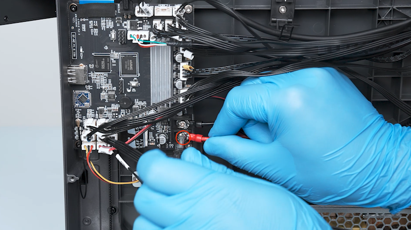
Loosen the two screws securing the power wires with a Phillips screwdriver.
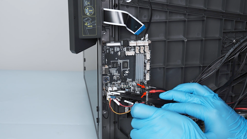
-
Unplug the power wires.
-
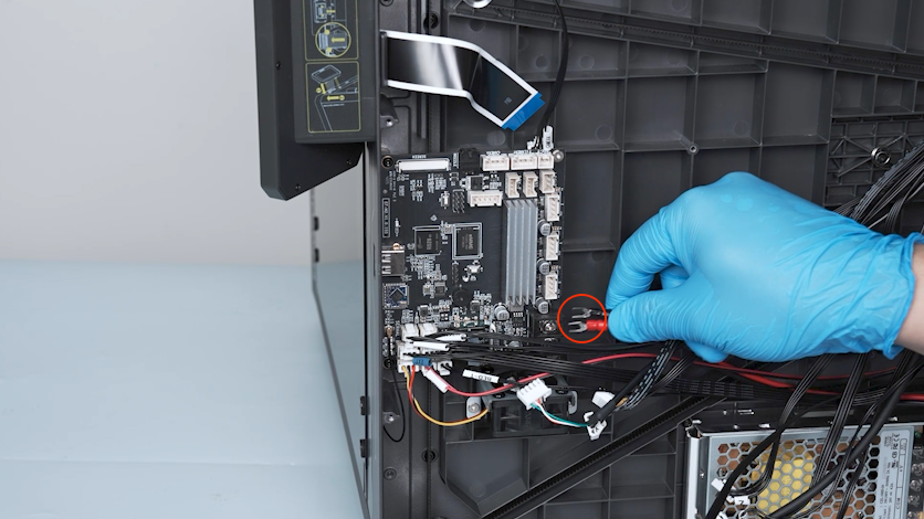
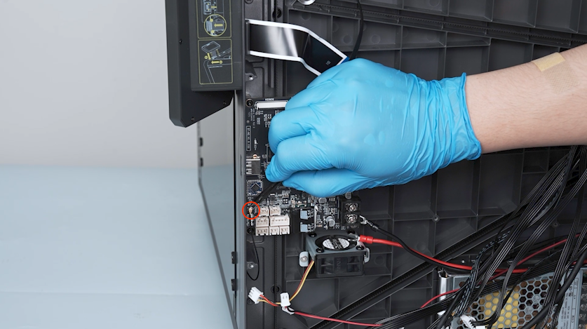
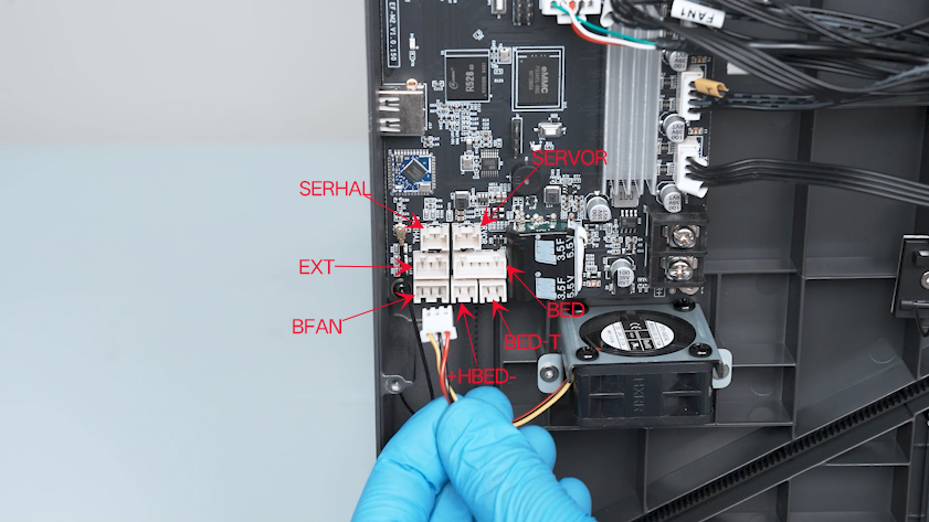
Remove the plugs on the lower side of the motherboard.
-
Unplug the Wi-Fi antenna with a pair of tweezers.
-
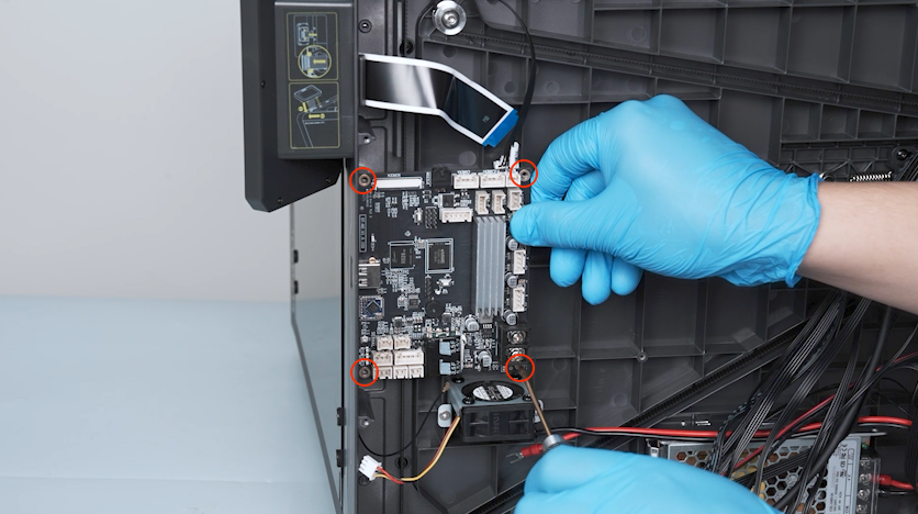
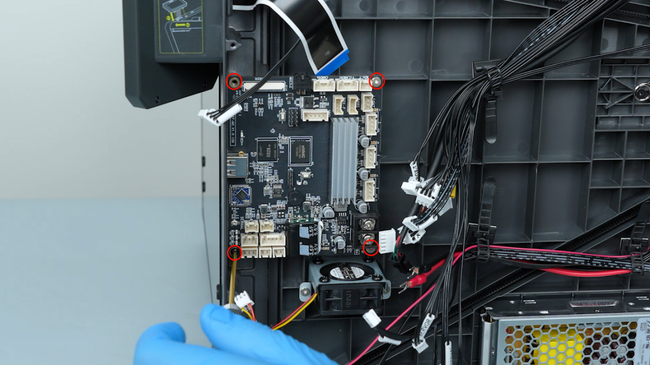
Release and remove the four screws securing the motherboard with a 2.0 mm Allen key and remove the motherboard.
Note: Hold the motherboard when releasing the last screw.
-
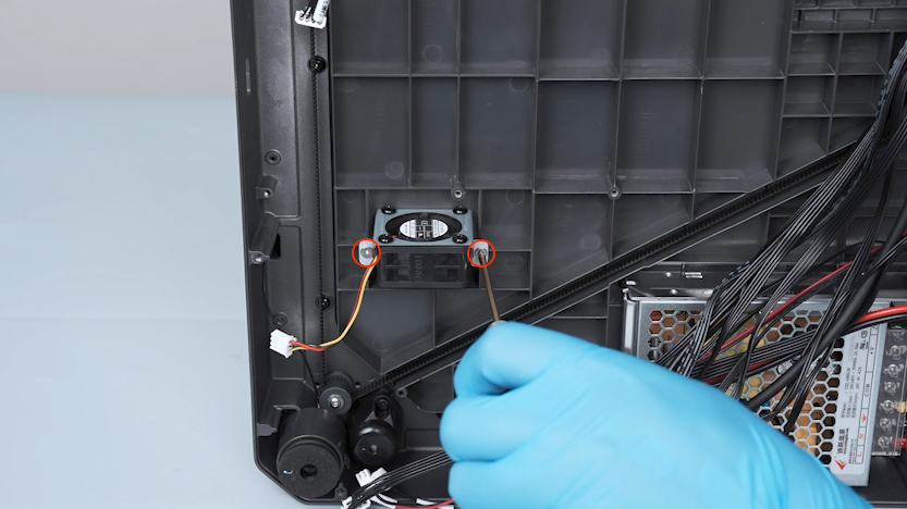
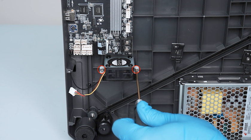
Release and remove the two screws securing the motherboard cooling fan with a 2.0 mm Allen key and remove the motherboard cooling fan.
¶ Remove the power supply
-
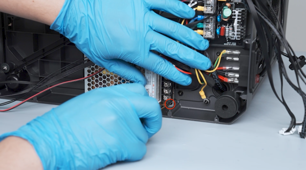
Lift the cover of the power wires and loosen the five screws securing the power wires with a Phillips screwdriver.

-
Unplug the power wires.
-
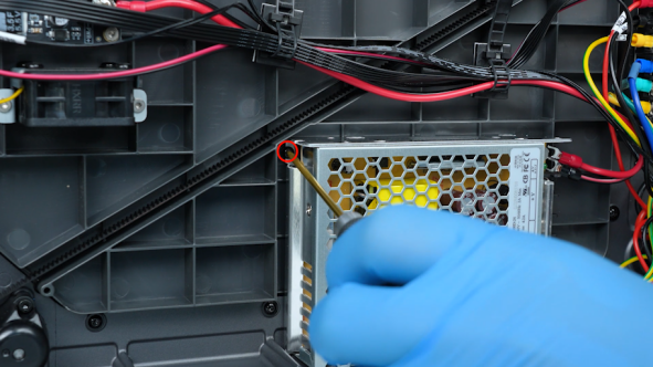
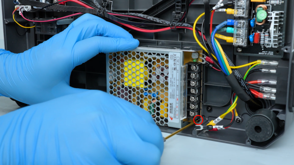
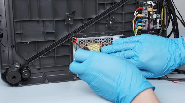
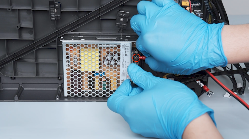
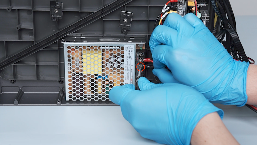
Release and remove the two screws securing the power supply with a 2.0 mm Allen key.
-
Remove the power supply.
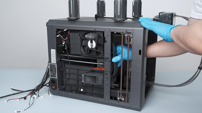
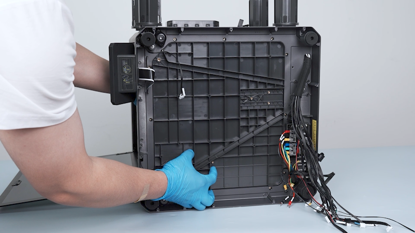
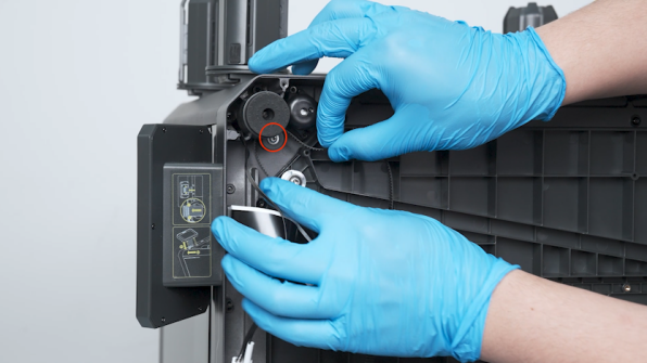
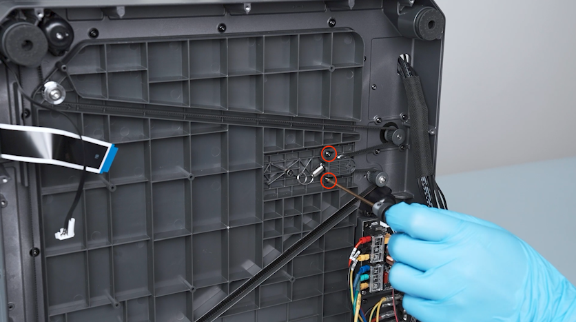
¶ Remove the Z-axis timing belt and the Z-axis timing pulley
-
Release and remove the two screws securing the Z-axis timing belt tensioner with a 2.0 mm Allen key.
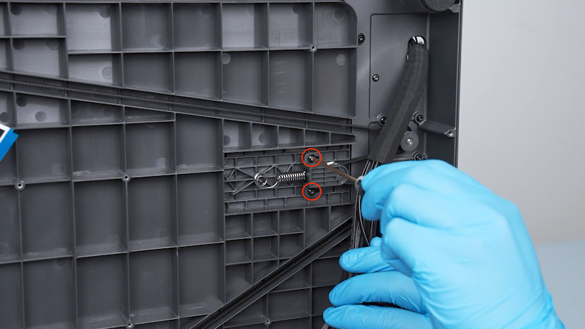
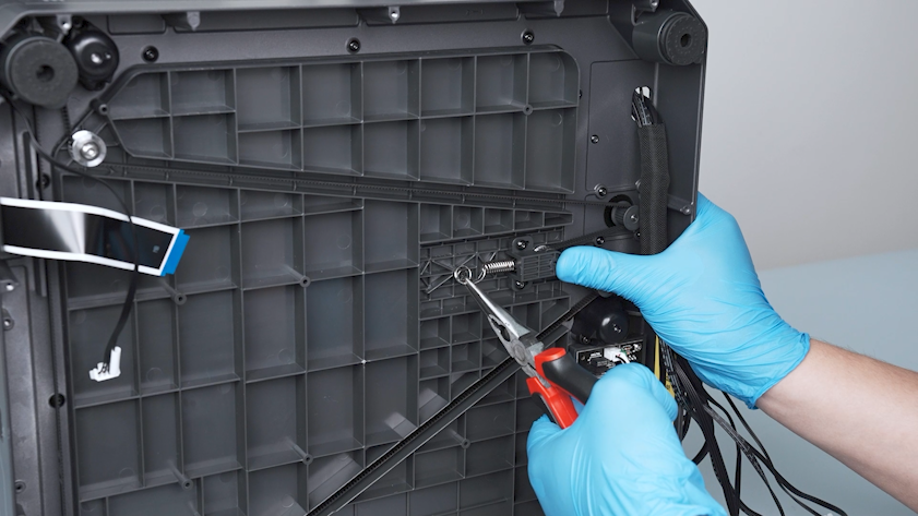
-
Remove the spring with a pair of pliers and remove the spring.
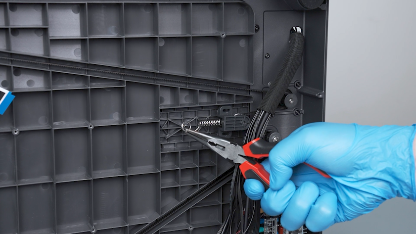
-
Remove the Z-axis timing belt.
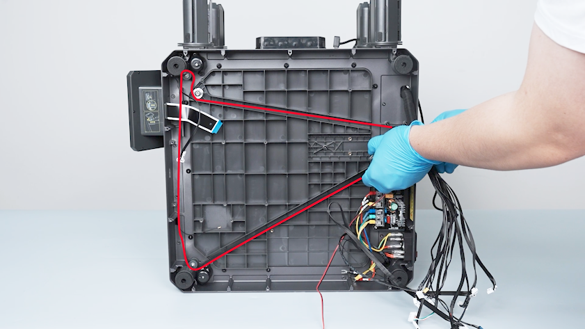
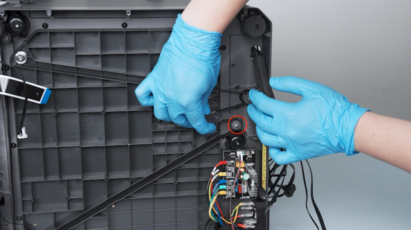
-
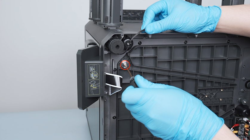
Release and remove the screw securing the spring with a 2.0 mm Allen key.
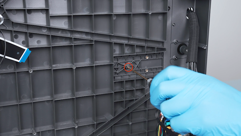
-
Release and remove the screw securing the Z-axis timing pulley with a 2.5 mm Allen key and remove the Z-axis timing pulley.
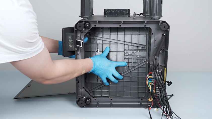
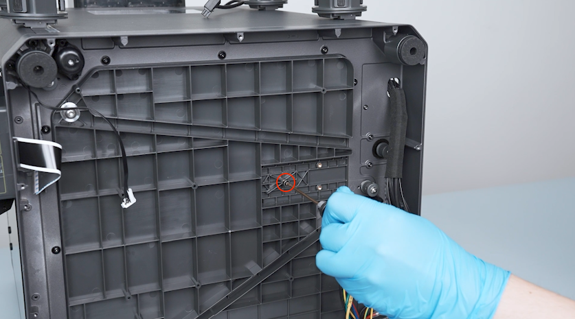
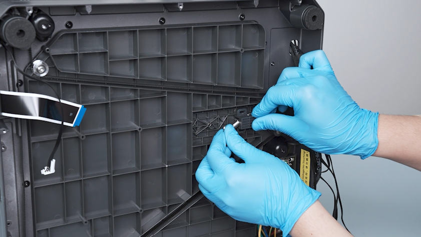
¶ Remove the old upper frame board
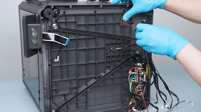
-
Release and remove the two screws on the lower side of the partition with a 2.0 mm Allen key.
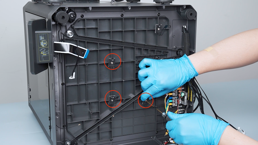
-
Release and remove the twelve screws securing the upper frame board with a 2.0 mm Allen key.
-
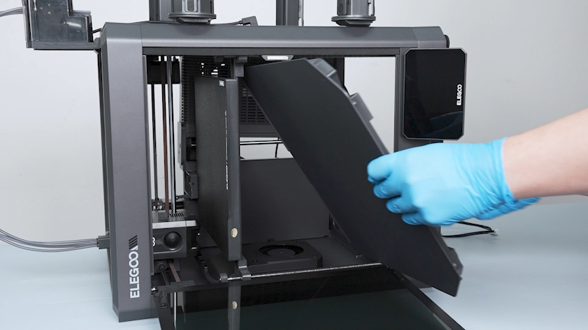
Open the front door.
-
Move the partition slightly to the right.
-
Gently push the upper frame board towards the chamber.
-
Lift the upper frame board from the front door side.
¶ Install the new upper frame board
-
Install the new upper frame board from the front door side.
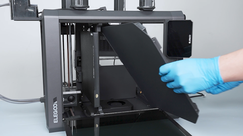
-
Adjust the position of the upper frame board and align it with the screw holes.
-
Tighten the twelve screws securing the upper frame board.
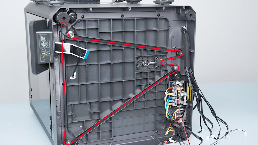
¶ Install the Z-axis timing belt and the Z-axis timing pulley
-
Tighten the two screws securing the bottom of the partition.
-
Tighten the Z-axis timing pulley.
-
Tighten the screw securing the spring.
-
Install the Z-axis timing belt onto the timing pulleys one by one.

-
Put the spring in the installation position.
-
Install the two screws securing the Z-axis timing belt.
Note: Do not tighten the screws at this time.
-
Press the tensioner of the Z-axis timing belt and pull the spring taut to its original position with a pair of pliers.
-
Tighten the two screws securing the Z-axis timing belt tensioner.
-
Put the cable tie in the installation position and tighten the screw securing the cable tie.
-
Install the other three cable ties in the same way.
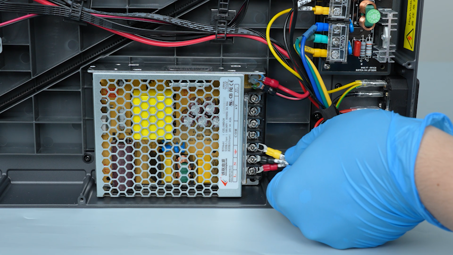
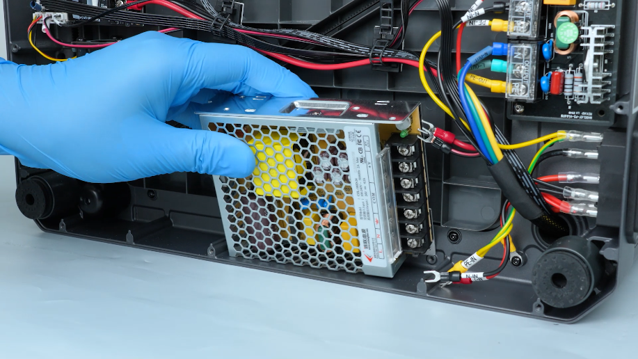
¶ Install the power supply
-
Put the power supply in the installation position and tighten the two screws securing the power supply.
-
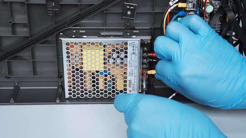
Insert the red wire into the V+ port and secure the screw securing the wire.
-
Insert the black wire to the COM port and secure the screw securing the wire.
-
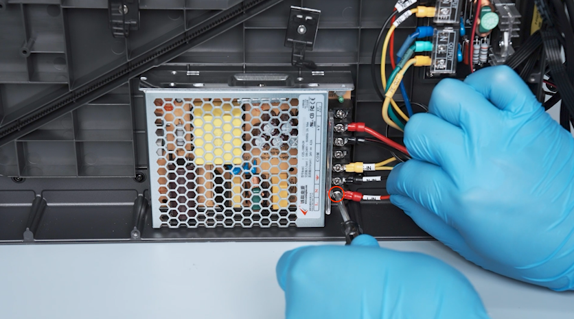
Insert the wire with the PE-IN terminal into the grounding port and secure the screw securing the wire.
-
Insert the wire with the N-IN terminal into the N port and secure the screw securing the wire.

-
Insert the wire with the L-IN terminal into the L port and secure the screw securing the wire.
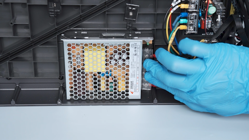
-
Close the power supply cover.
¶ Install the motherboard
-
Put the motherboard in the installation position and tighten the four screws securing the motherboard.
-
Put the motherboard cooling fan in the installation position and tighten the two screws securing the motherboard cooling fan.
-
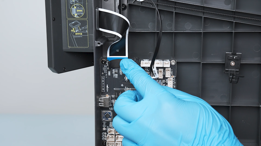
Plug in the touch screen ribbon cable and press the clip.
-
Secure the touch screen ribbon cable with tape.
-
Insert the plugs on the upper and right sides of the motherboard.
-
Plug in the Wi-Fi antenna onto the motherboard.
-
Insert the plugs on the lower side of the motherboard.
-
Insert the black wire into the PWR- port on the motherboard and secure the screw securing the fuse of the power wire.
-
Insert the red wire into the PWR+ port on the motherboard ans secure the screw securing the fuse of the power wire.
-
Secure the wires with cable ties.
¶ Install the bottom cover, back cover and partition
-
Put the bottom cover in the installation position and tighten the ten screws securing the bottom cover with a 2.0 mm Allen key.
-
Tighten the screw securing the upper part of the partition.
-
Tighten the six screws securing the back side of the partition.
-
Get the back cover and lay it flat on the table. Tighten the two screws securing the CANVAS extension cable with a 2.0 mm Allen key.
-
Lift the back cover and put the CANVAS extension cable into the gap on the chamber cooling fan side.
-
Put the back cover in the installation position and tighten the sixteen screws securing the back cover.
Note: Screws labelled by the red circle are M3 x 8, and those labelled by the yellow circle are M3 x 4.
-
Plug in the communication cable of the CANVAS.
¶ Verification
-
Plug in the power supply cable and turn the power switch ON (symbol "|").
-
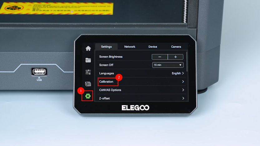
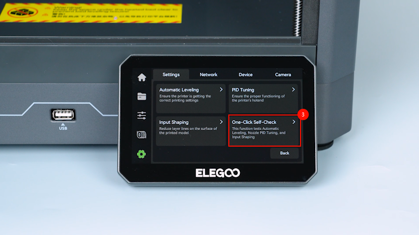
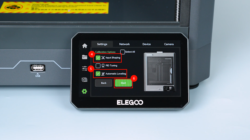
On the touch screen, select Settings - Calibrate - One-Click Self-Check - Input Shaping - Auto Leveling - Confirm.
-
The printer is ready for use after the self check.
¶ Help us improve
If you have any ideas about the wiki pages, please let us know via ELEGOO official feedback channel