¶ Operation Steps for Each Model
The steps below are based on Centauri Carbon 2 Combo. For Centauri Carbon 2, skip the steps related to parts that are not installed.
| Model | Action | Steps to Skip |
|---|---|---|
| Centauri Carbon 2 Combo | Follow all steps | None |
| Centauri Carbon 2 | Skip steps related to CANVAS components |
|
| Centauri 2 Combo | Skip enclosure-related steps only if the enclosure is not installed |
|
| Centauri 2 | Skip steps related to CANVAS components |
|
If your printer has optional accessories installed, such as CANVAS or an enclosure, follow the steps related to those parts.
¶ Tools and Materials
-
A 1.5 mm Allen key
-
A 2.0 mm Allen key
-
A pair of tweezers
-
A new LED strip
¶ Tutorial Video
https://www.youtube.com/watch?v=E2oG2h3fCGE&feature=youtu.be
¶ Instruction
¶ Preparation
-
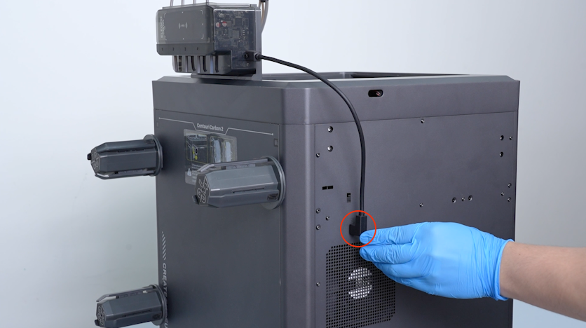
Plug in the power supply cable and turn the power switch ON (symbol "|").
-
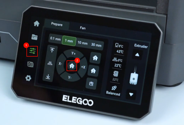
On the touch screen, select Control - Homing.
-
Wait for the printer to complete the homing process.
-
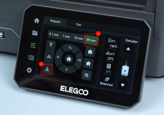
On the touch screen, select ↓ and lower the heated bed to the bottom.
-
Turn the power switch OFF (symbol "〇") and unplug the power supply cable.
¶ Remove the Old LED Strip
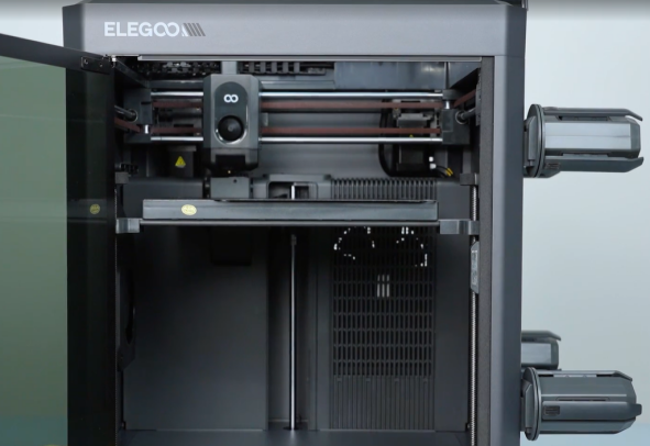
¶ Remove the Upper Frame Components
-
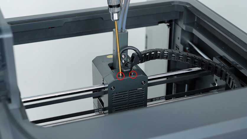
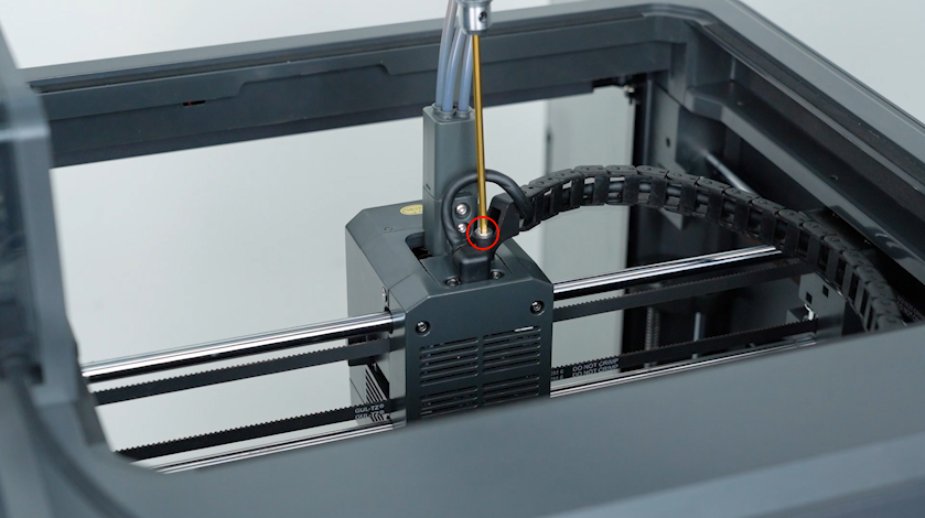
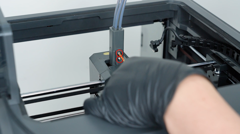
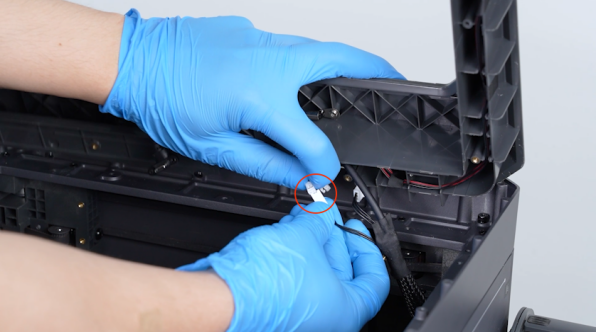
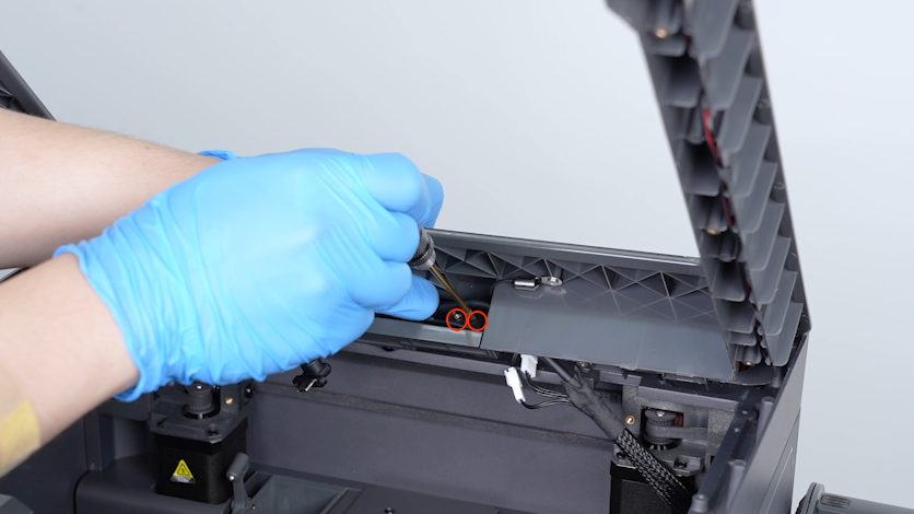
Release and remove the two screws securing the CAN bus with a 1.5 mm Allen key and unplug the CAN bus.
-
Release and remove the screw securing the tank chain with a 2.5 mm Allen key and remove the tank chain.
-
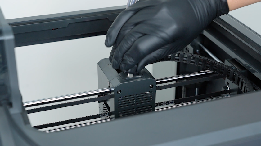
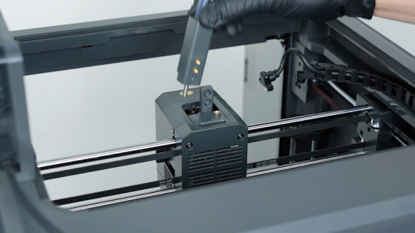
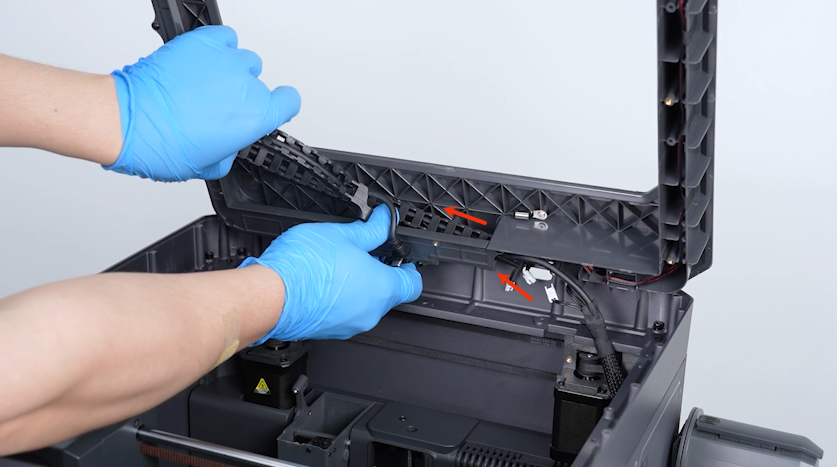
Release and remove the two screws securing the 4-in-1 hub with a 2.0 mm Allen key and remove the 4-in-1 hub.
-
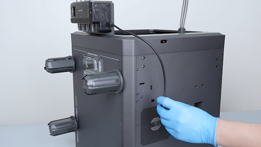
Unplug the CANVAS communication cable.
-
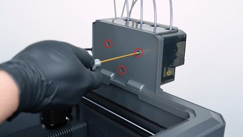
Release and remove the three screws securing the CANVAS with a 2.0 mm Allen key.
Note: Hold the CANVAS when releasing the last screw.
-
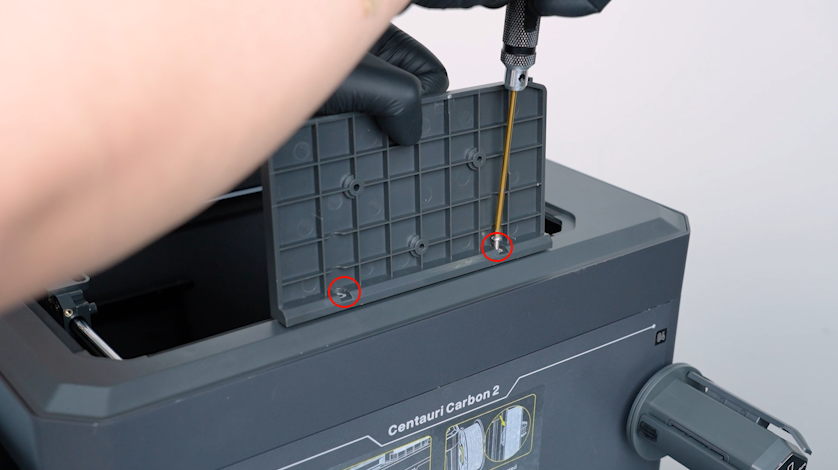
Release and remove the two screws securing the CANVAS holder with a 2.0 mm Allen key and remove the CANVAS holder.
¶ Remove the Upper Frame Housing
-
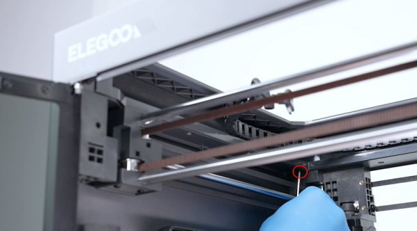
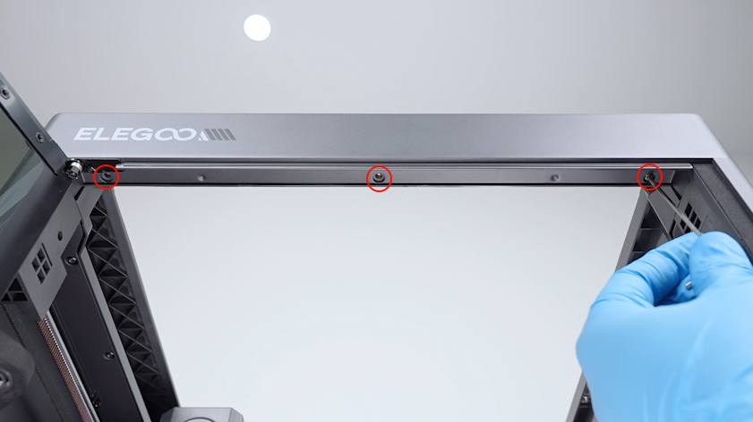
Release and remove the three screws securing the front side of the upper frame housing with a 2.0 mm Allen key.
-
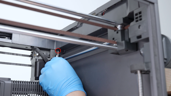
Release and remove the four screws securing the left side of the upper frame housing with a 2.0 mm Allen key.
-
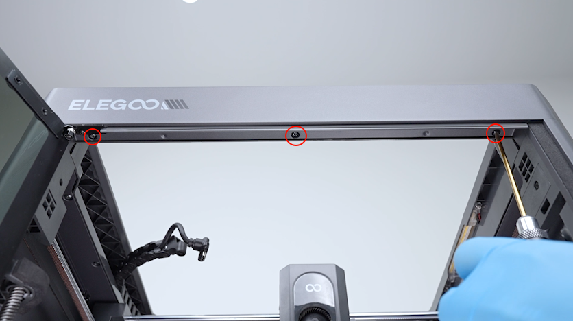
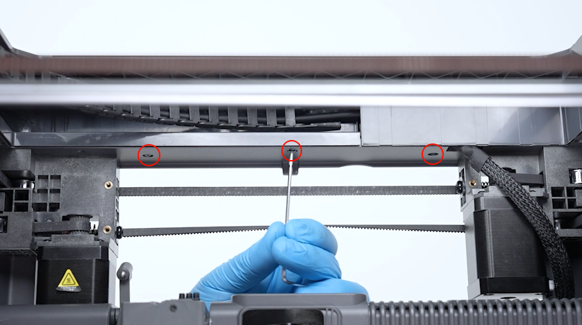
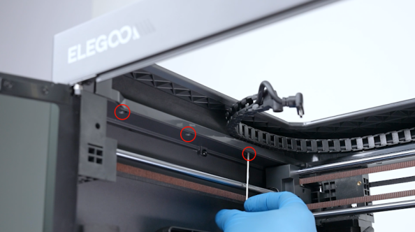
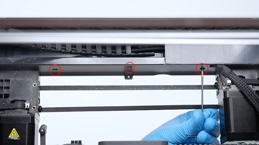
Release and remove the three screws securing the back side of the upper frame housing with a 2.0 mm Allen key.
-
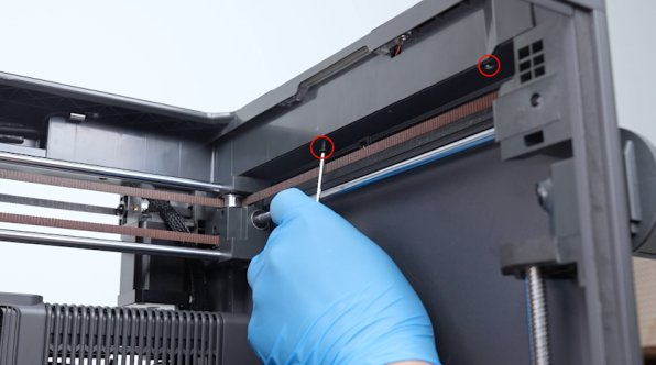
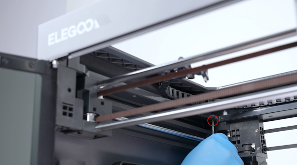
Release and remove the three screws securing the right side of the upper frame housing with a 2.0 mm Allen key.
-
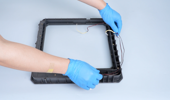
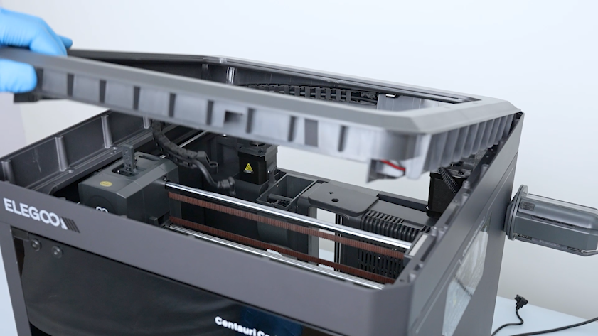
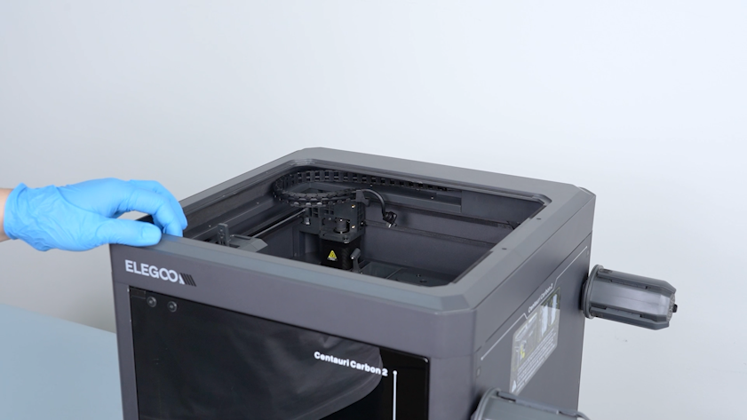
Lift the upper frame housing.
¶ Remove the Old LED Strip
-
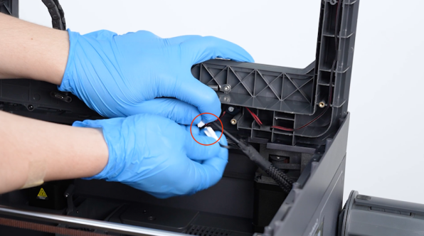
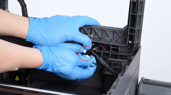
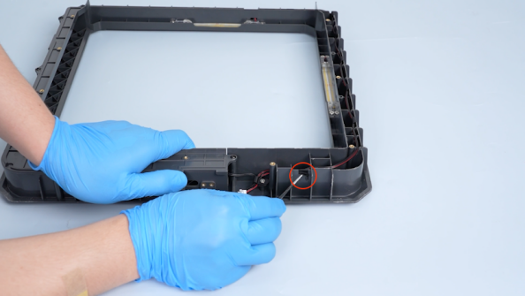
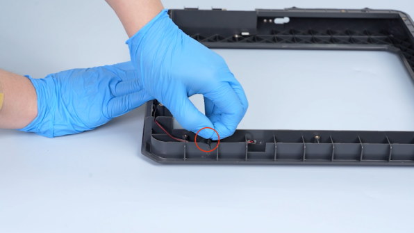
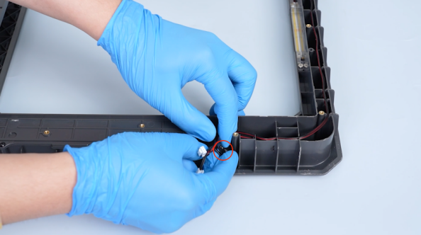
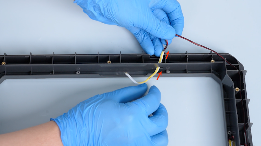
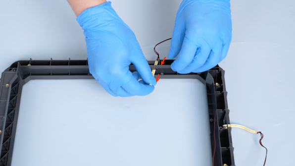
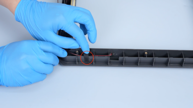
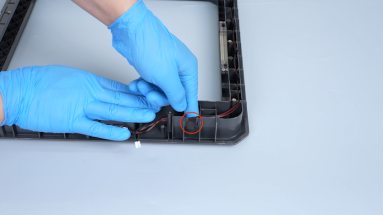
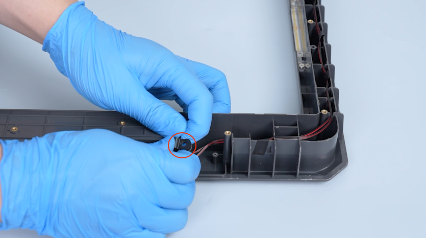
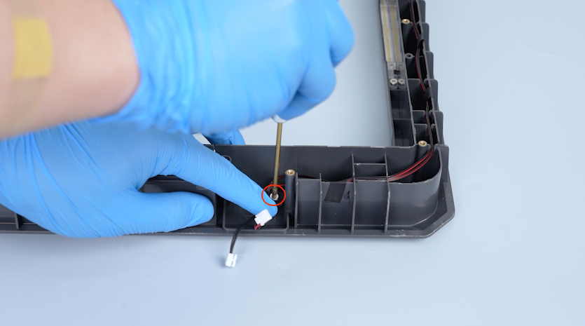
Remove the LED strip plug and the chamber thermistor adapter plug.
-
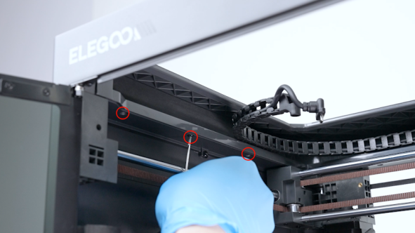
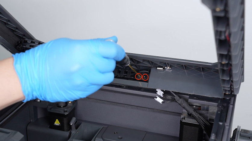
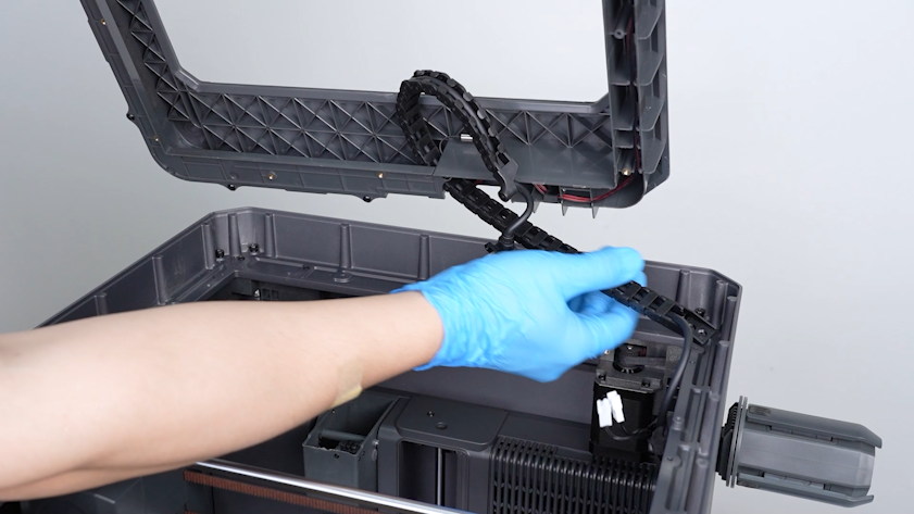
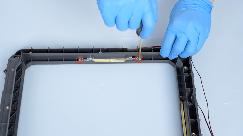
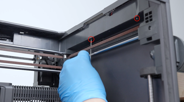
Release and remove the two screws securing the tank chain with a 2.0 mm Allen key.
-
Pull the tank chain out from the groove of the upper frame housing.
-
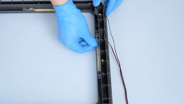
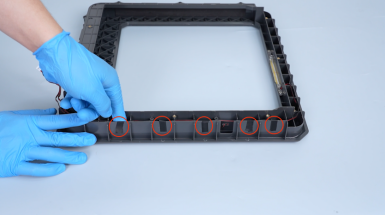
Remove the tape securing the LED strip wires.
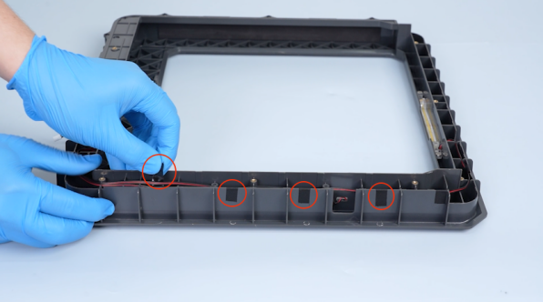
-
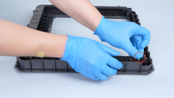
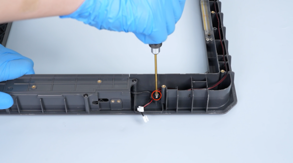
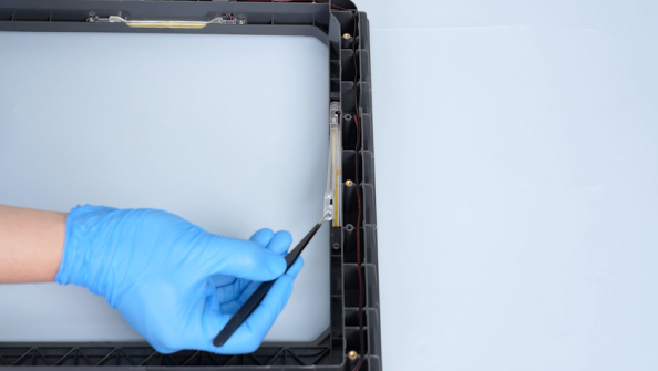
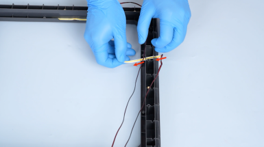
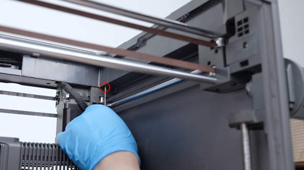
Release and remove the screw securing the clip with a 2.0 mm Allen key and remove the clip.
-
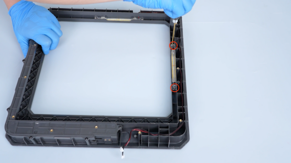
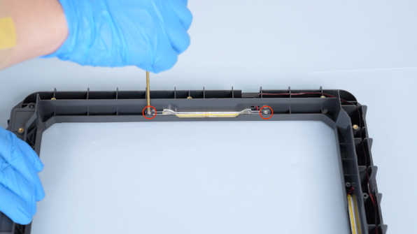
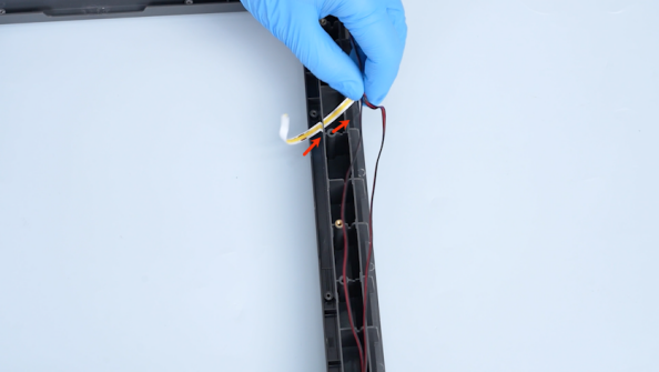
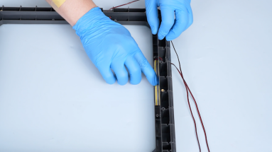
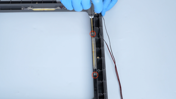
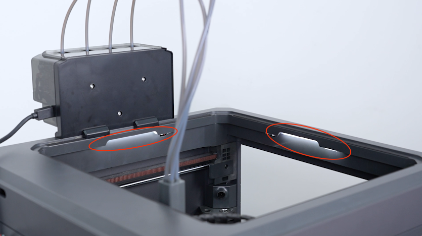
Release and remove the two screws securing the LED strip cover with a 2.0 mm Allen key and remove the LED strip cover with tweezers.
-
Remove the LED strip cover on the other side in the same way.
-
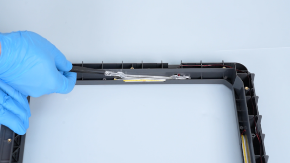
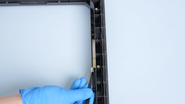
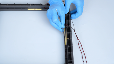
Remove the LED strip along the edge with tweezers.
-
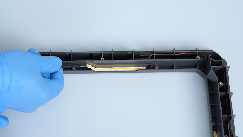
Remove the LED strip from the slot.
-
Remove the LED strip on the other side in the same way.
-
Remove the LED strip.
¶ Install the New LED Strip
¶ Install the LED Strip and Covers
-
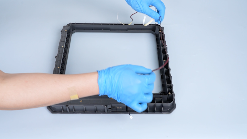
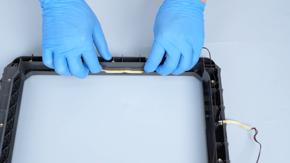
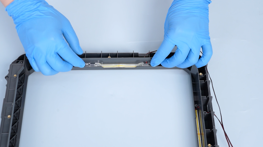
Pass the LED strip through the slot and put the new LED strip in the installation position.
-
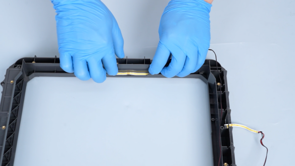
Adhere the LED strip to the back cover of the upper frame housing and press the LED strip with tweezers.
-
Install the LED strip on the other side in the same way.
-
Put the LED strip cover in the installation position.
-
Tighten the two screws securing the LED strip cover.
-
Install the LED strip cover on the other side in the same way.
¶ Reinstall the Upper Frame Components
-
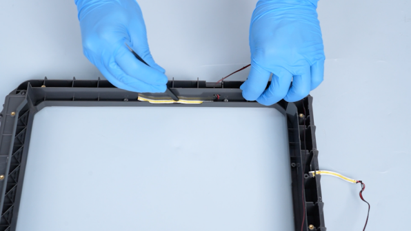
Adhere the tape.
-
Secure the wires with a clip.
-
Tighten the screw securing the clip with a 2.0 mm Allen key.
-
Place the upper frame housing on the top of the printer.

-
Pass the tank chain through the groove of the upper frame housing.
-
Insert the LED strip plug and the chamber thermistor plug.

-
Tighten the two screws securing the tank chain.
¶ Secure the Upper Frame Housing
-
Install the upper frame.
-
Tighten the three screws securing the front side of the upper frame housing.
-
Tighten the four screws securing the left side of the upper frame housing.
-
Tighten the three screws securing the back side of the upper frame housing.
-
Tighten the three screws securing the right side of the upper frame housing.
¶ Reinstall the CANVAS and CAN Bus
-
Put the CANVAS holder in the installation position and tighten the two screws.
-
Put the CANVAS in the installation position and tighten the three screws.
-
Plug in the communication cable of the CANVAS.
-
Install the 4-in-1 hub and tighten the two screws.
-
Plug in the CAN bus and tighten the two screws with a 1.5 mm Allen key.
-
Put the tank chain in the installation position and tighten the screw.
¶ Verification
-
Plug in the power supply cable and turn the power switch ON (symbol "|").
-
On the touch screen, turn on the LED strip.
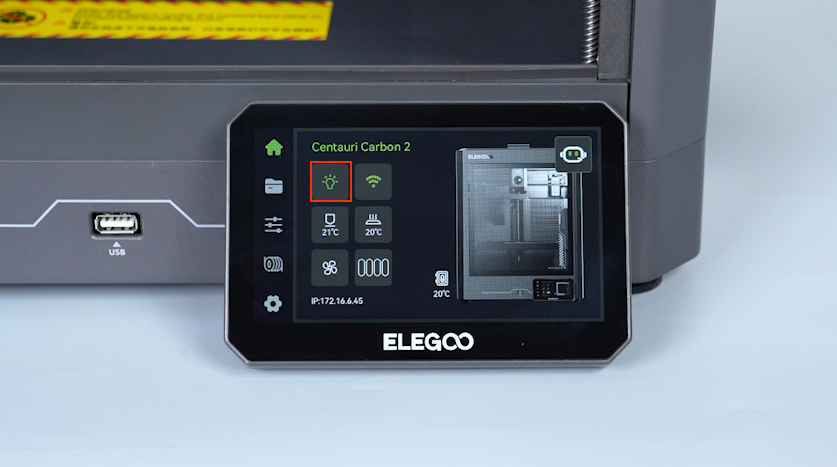
-
Confirm that the LED strip lights up normally. The LED strip is replaced successfully.
¶ Help us improve
If you have any ideas about the wiki pages, please let us know via ELEGOO official feedback channel