¶ Operation Steps for Each Model
The steps below are based on Centauri Carbon 2 Combo. For other models, skip the steps related to parts that are not installed.
| Model | Action | Steps to Skip |
|---|---|---|
| Centauri Carbon 2 Combo | Follow all steps | None |
| Centauri 2 Combo | Skip enclosure-related steps only if the enclosure is not installed |
|
| Centauri Carbon 2 | Skip CANVAS / 4-in-1 hub related steps |
|
| Centauri 2 | Skip enclosure and CANVAS / 4-in-1 hub related steps if they are not installed |
|
If your printer has optional accessories installed, such as CANVAS or an enclosure, follow the steps related to those parts.
¶ Tools and Materials
- 1.5 mm Allen key
- 2.0 mm Allen key
- 2.5 mm Allen key
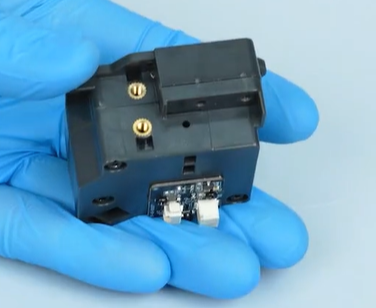
- A new gearbox
¶ Tutorial Video
https://www.youtube.com/watch?v=0XCBpwRAjXE&feature=youtu.be
¶ Instructions
¶ Prepare the Printer
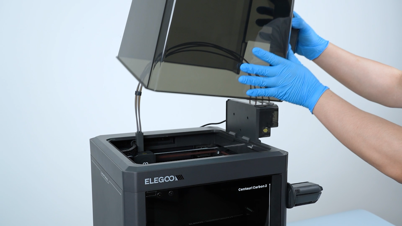
- Remove the lid.
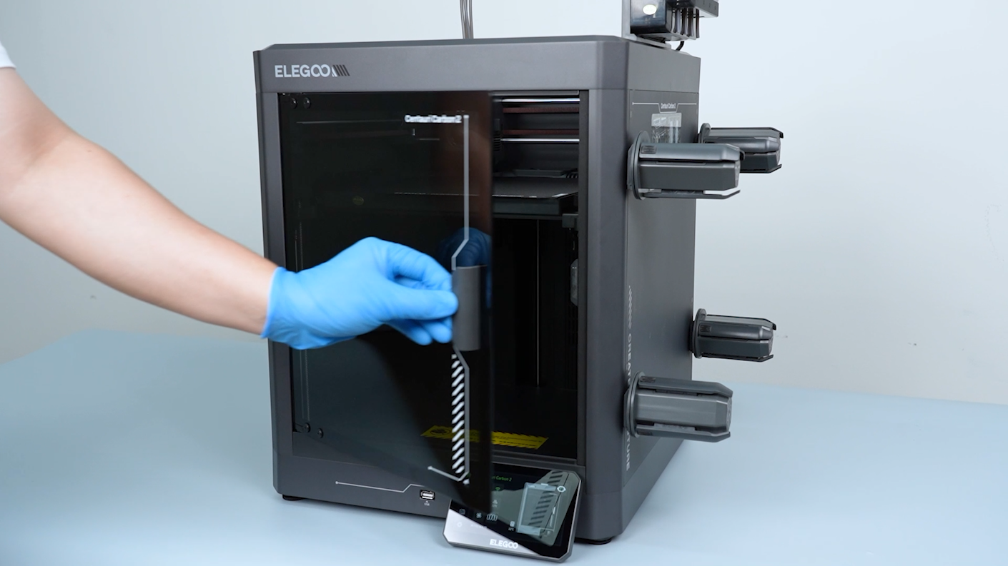
- Open the front door.
- On the touch screen, select Control - Homing. Wait for the XYZ homing process to complete.
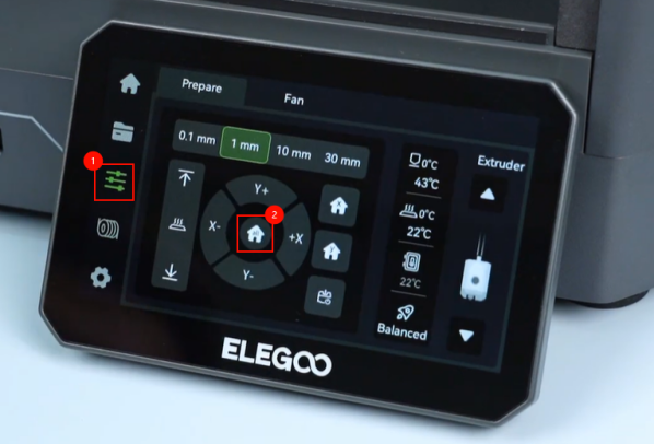

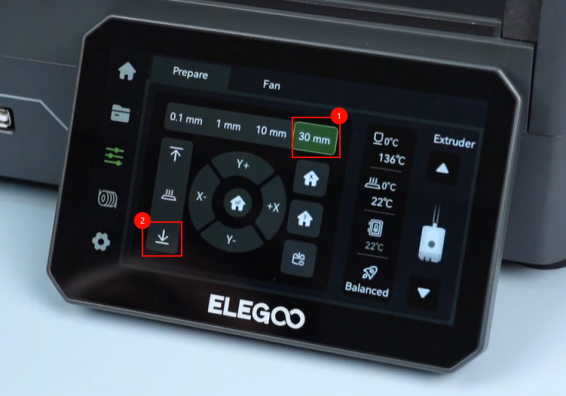
- On the touch screen, select 30 mm as the motor movement distance. Select ↓ to lower the heated bed to the bottom.
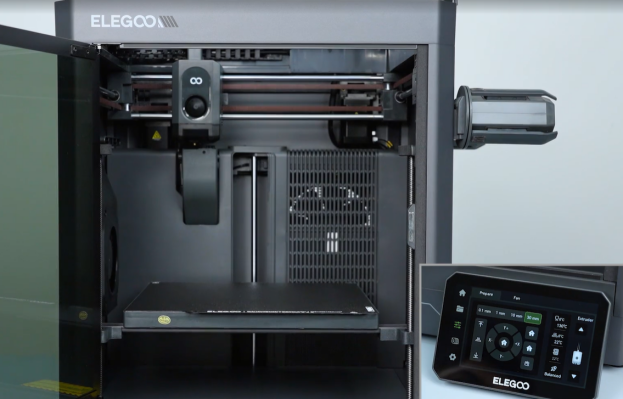
- Turn the power switch OFF (symbol 〇) and unplug the power supply cable.
¶ Remove the Extruder Communication Cable and Drag Chain
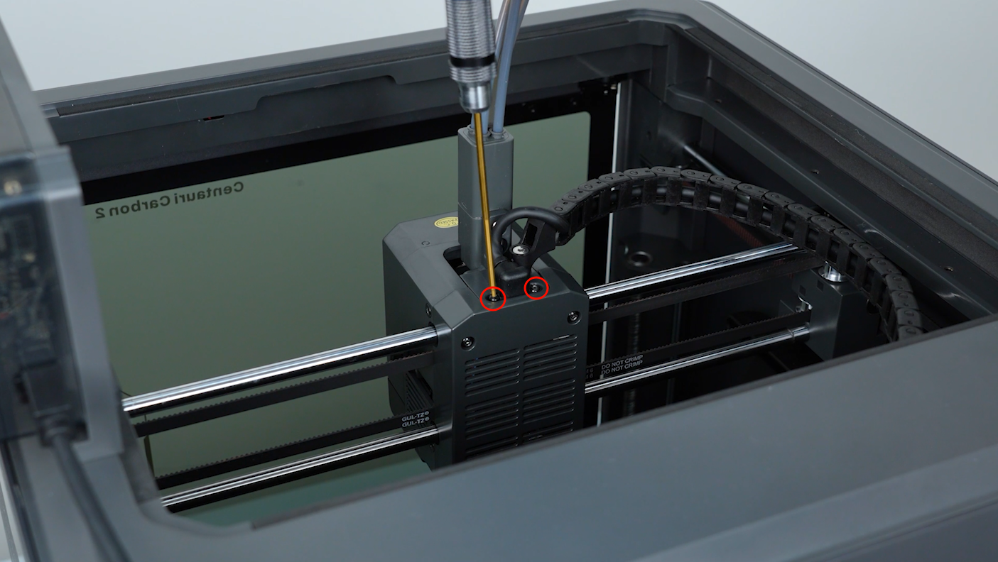
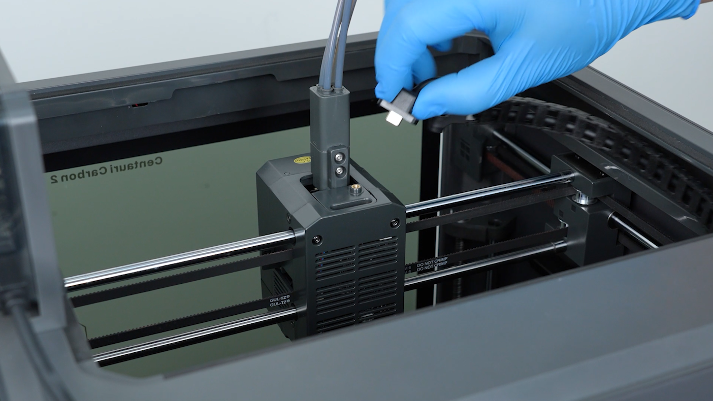
- Loosen the two screws securing the extruder communication cable with a 1.5 mm Allen key. Remove the screws with a pair of tweezers.
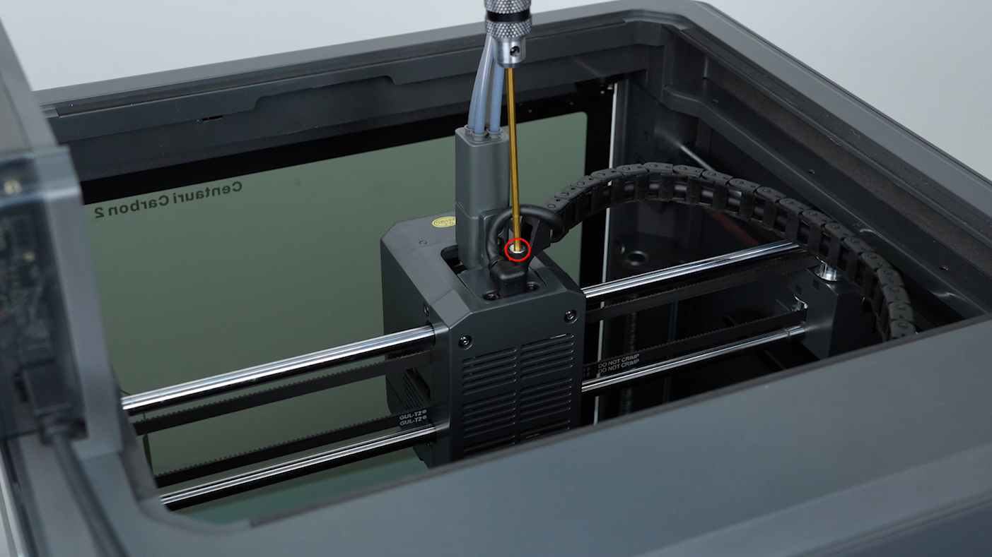
- Loosen the screws securing the drag chain with a 2.5 mm Allen key. Remove the screws with a pair of tweezers.
- Unplug the extruder communication cable.
¶ Remove the 4-in-1 Hub
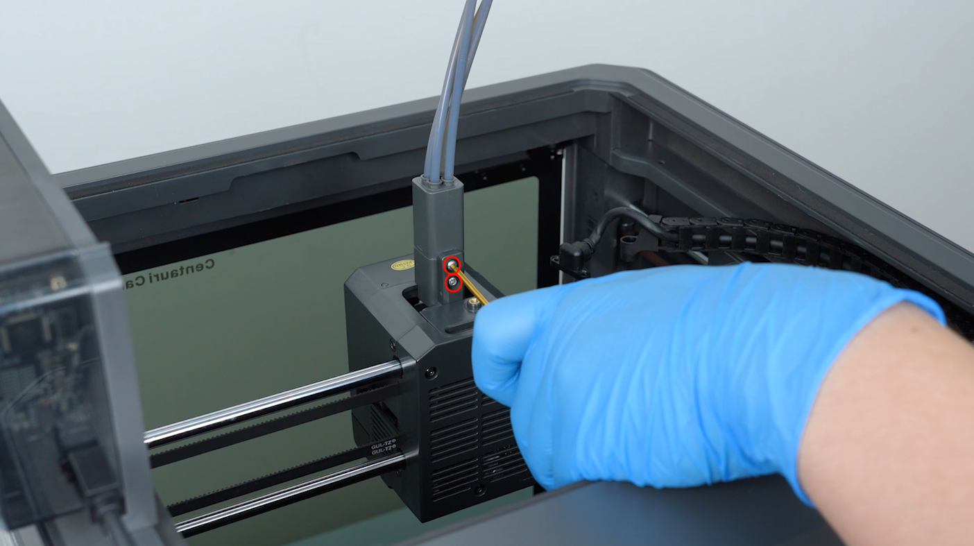
- Loosen the two screws securing the 4-in-1 hub with a 2.0 mm Allen key. Remove the screws with a pair of tweezers.
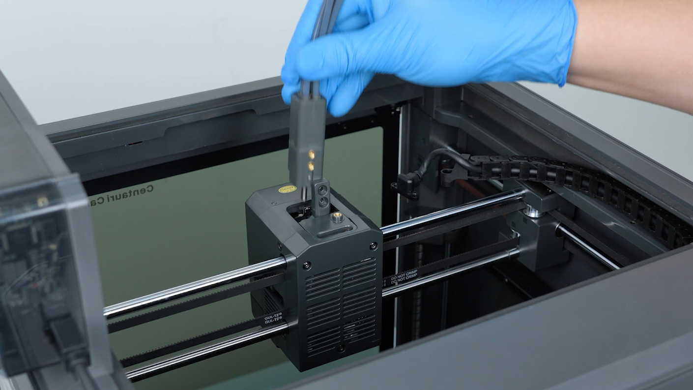
- Remove the 4-in-1 hub.
¶ Remove the Tool Head Cover and Housing
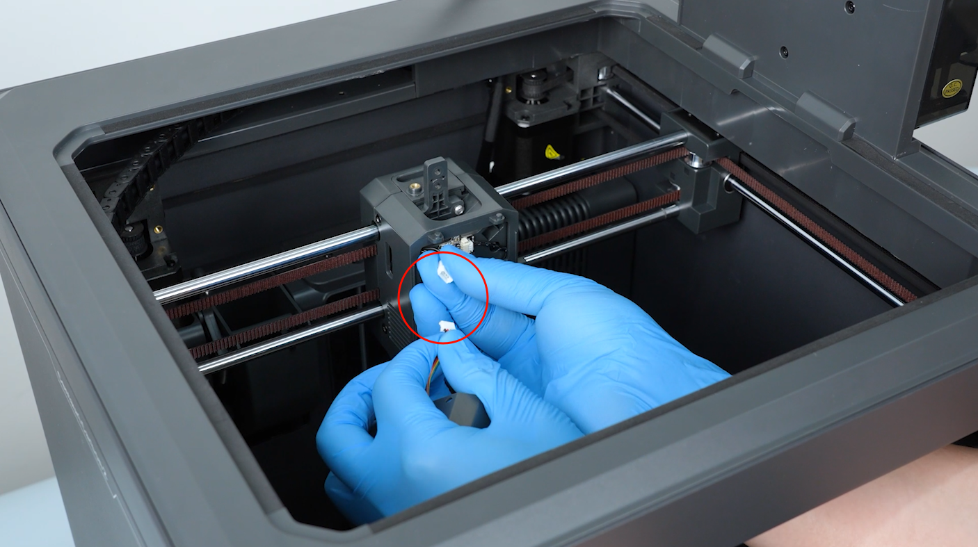
- Open the front cover of the tool head. Unplug the cable of the model cooling fan.
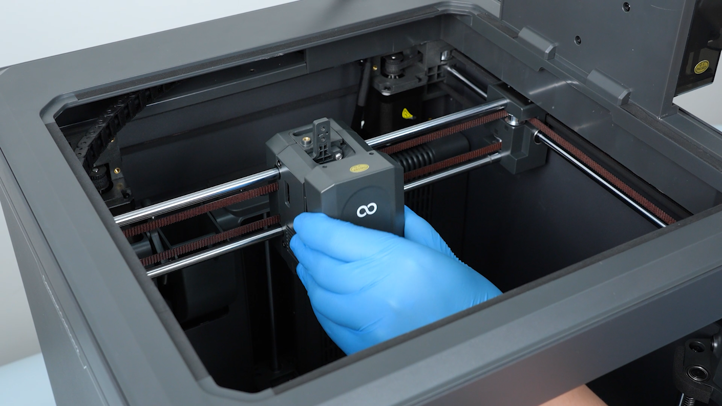
- Remove the front cover of the tool head.
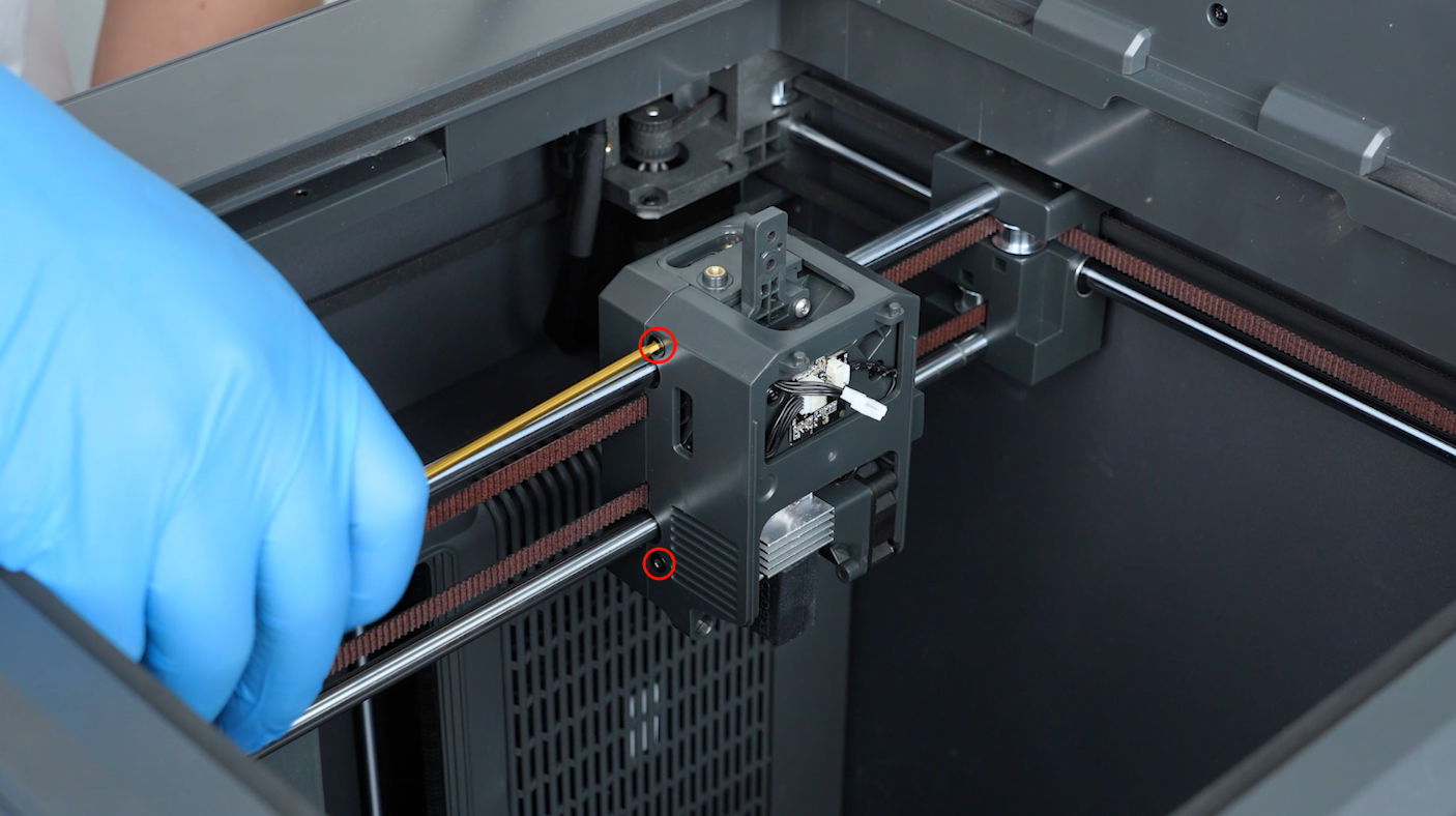
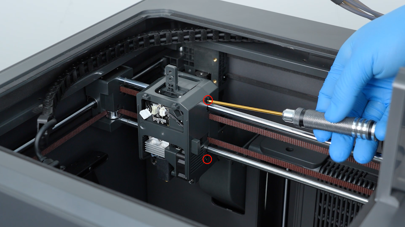
- Release and remove the four screws securing the tool head housing with a 2.0 mm Allen key.
- Remove the tool head housing.
¶ Remove the Hotend and 4-in-1 Hub Holder
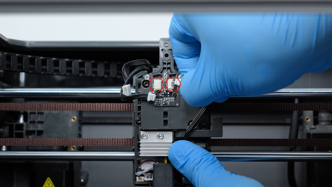
- Remove the two plugs on the filament sensor board.
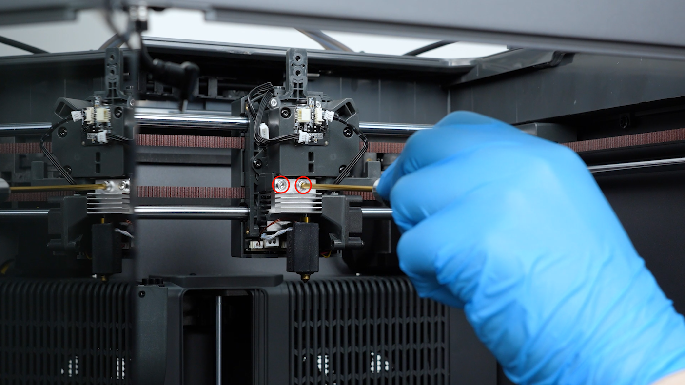
- Loosen the two screws securing the hotend with a 2.5 mm Allen key. Remove the screws with a pair of tweezers. Remove the hotend.
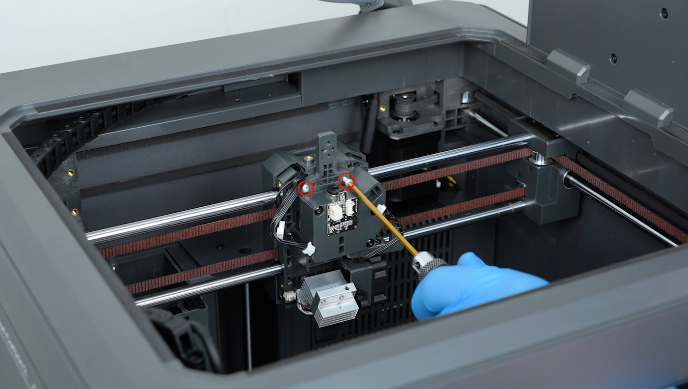
- Loosen the two screws securing the 4-in-1 hub holder with a 2.0 mm Allen key. Remove the screws with a pair of tweezers. Remove the 4-in-1 hub holder.
¶ Remove the Old Gearbox
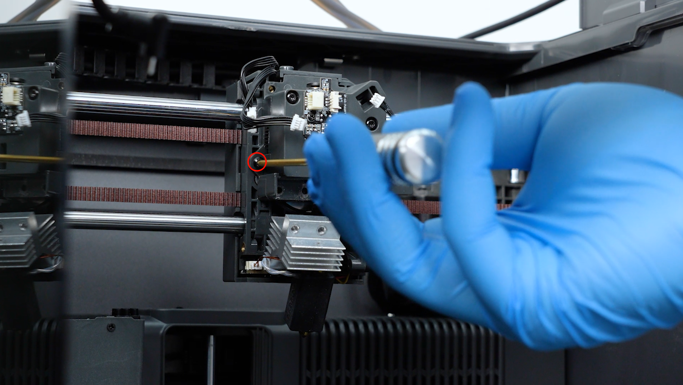
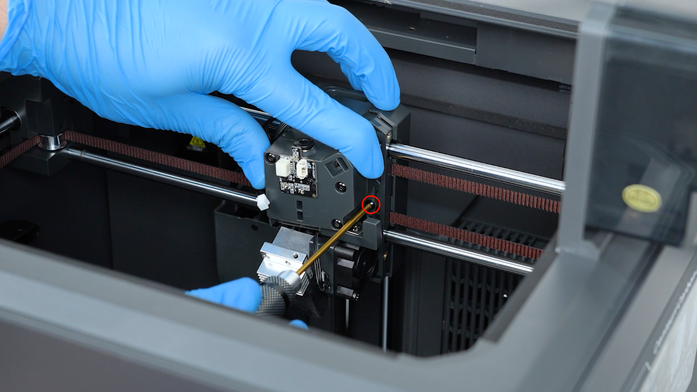
- Loosen the screws securing the gearbox with a 2.0 mm Allen key. Remove the screw with a pair of tweezers.
- Remove the gearbox.
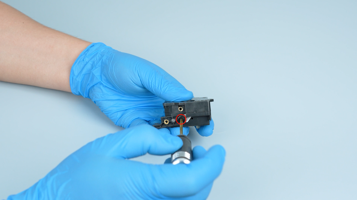
- Release and remove the screw securing the spring with a 2.0 mm Allen key. Remove the spring.

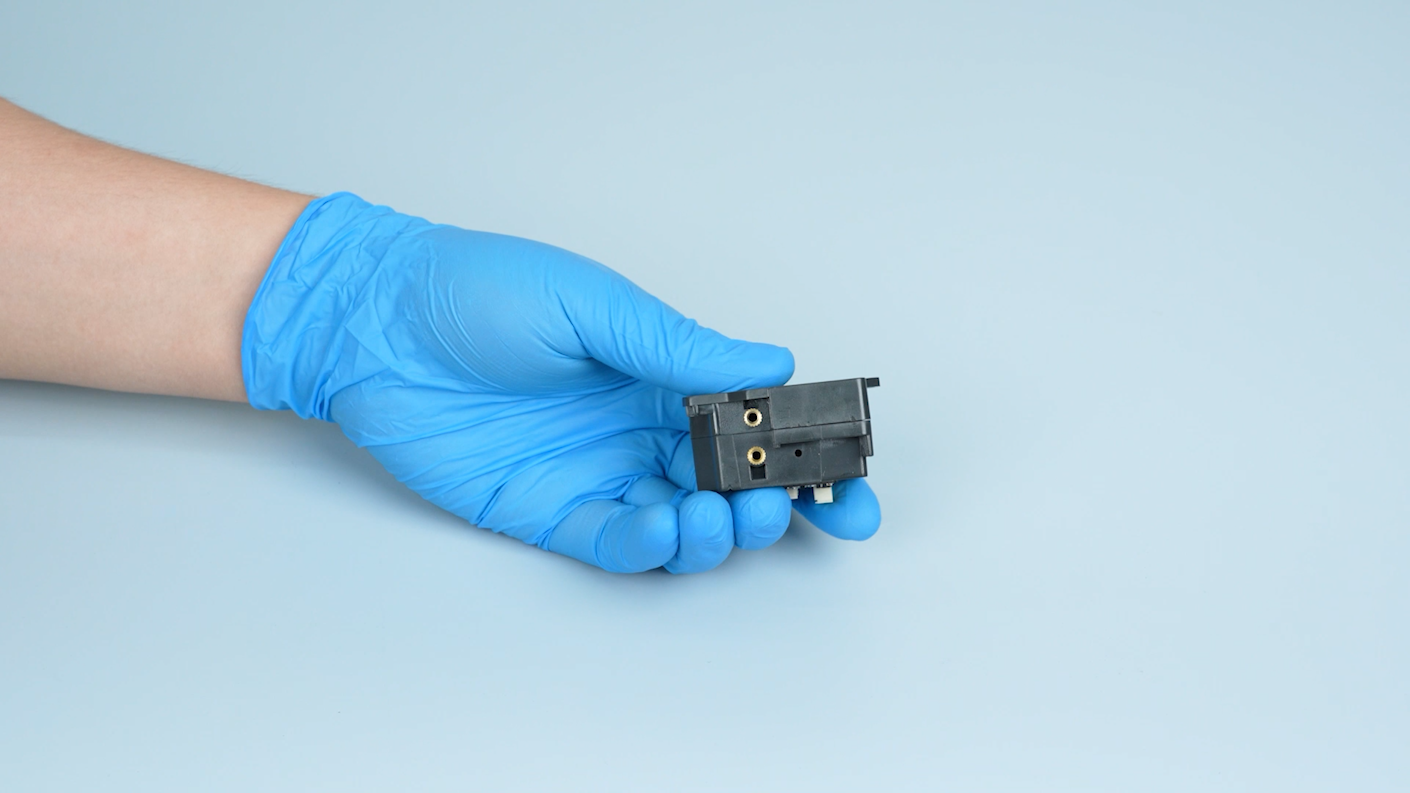
- Release and remove the two screws securing the cutter assembly with a 2.0 mm Allen key. Remove the cutter assembly. Remove the old gearbox.
The blade is sharp. Take care not to cut your fingers when removing it.
¶ Install the Cutter Assembly
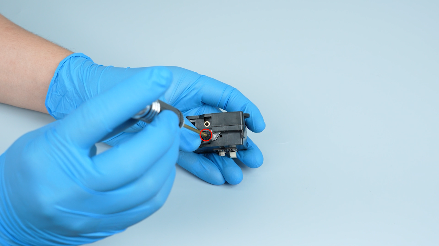
- Get the new gearbox. Put the cutter assembly in the installation position and tighten the screw to secure it.
¶ Install the Spring
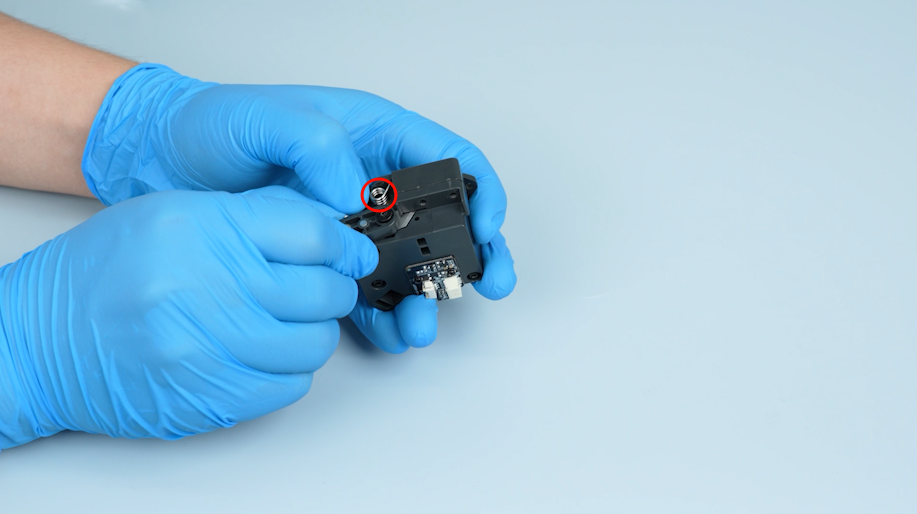
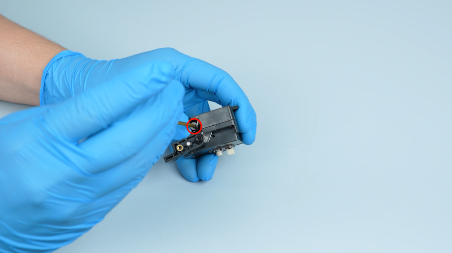
- Put the spring in the installation position. Tighten the screw to secure the spring.
¶ Install the New Gearbox
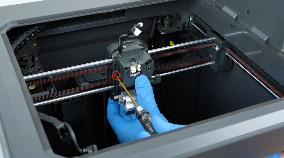
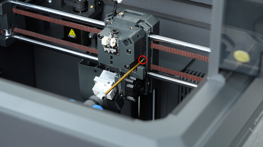
- Put the gearbox in the installation position and tighten the screws.
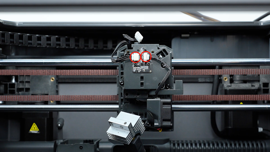
- Insert the plugs into the filament sensor board.
¶ Reinstall the Hotend and 4-in-1 Hub Holder
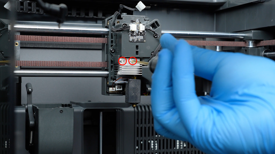
- Put the hotend in the installation position. Tighten the two screws securing the hotend with a 2.5 mm Allen key.
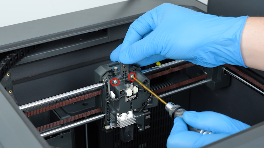
- Put the 4-in-1 hub holder in the installation position. Tighten the screws to secure the holder.
¶ Reinstall the Tool Head Housing and Front Cover
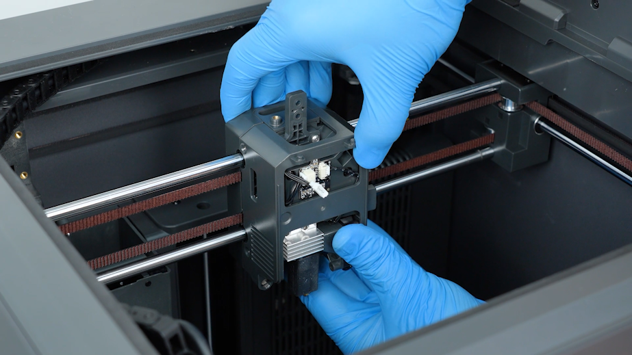
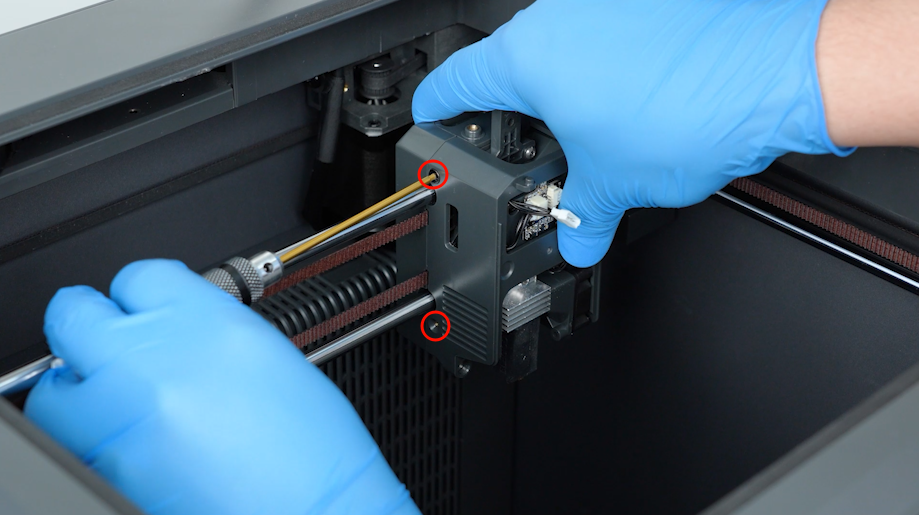
- Put the tool head housing in the installation position. Tighten the screws to secure the housing.
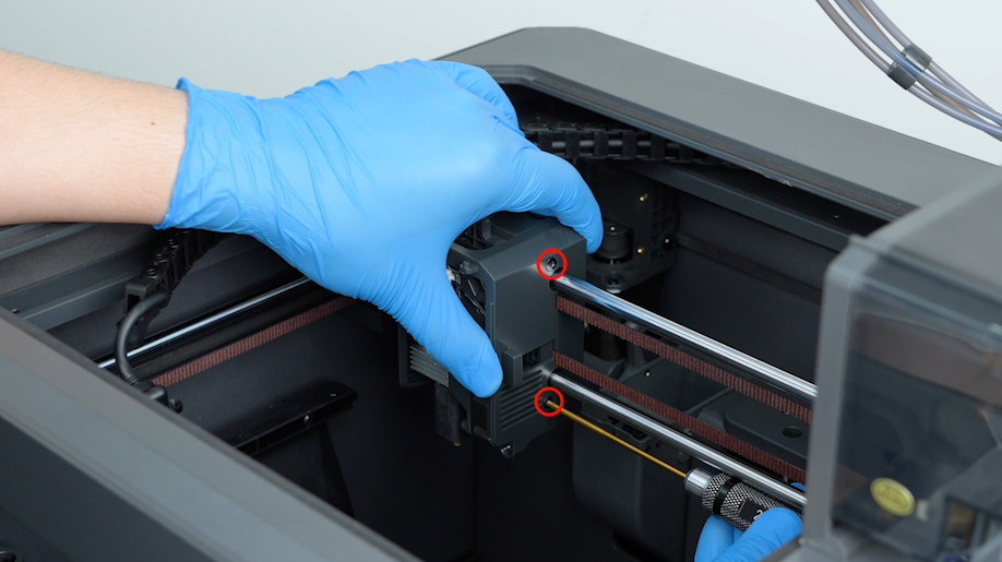
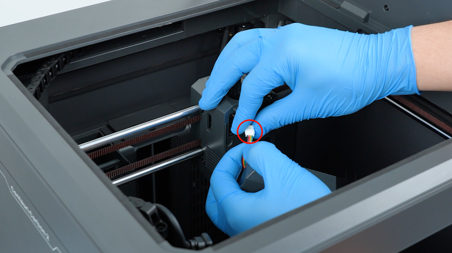
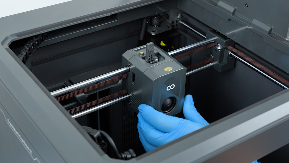
- Plug in the model cooling fan cable. Install the front cover of the tool head.
¶ Reinstall the 4-in-1 Hub, Extruder Communication Cable, and Drag Chain
- Put the 4-in-1 hub in the installation position and tighten the two screws securing it.
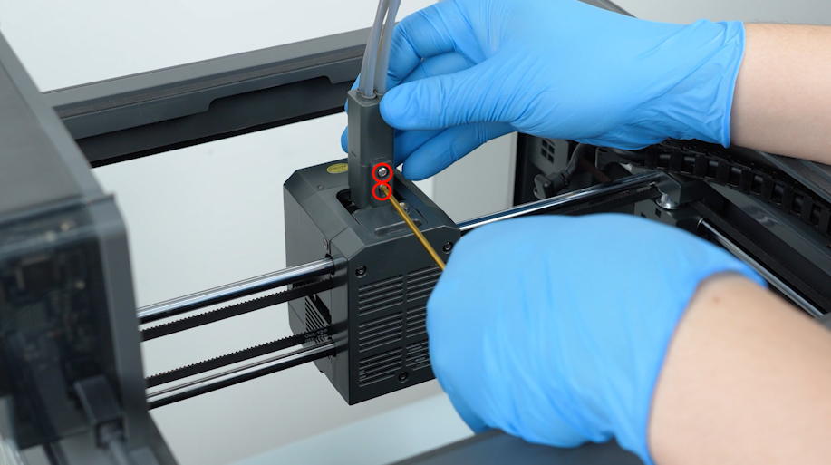
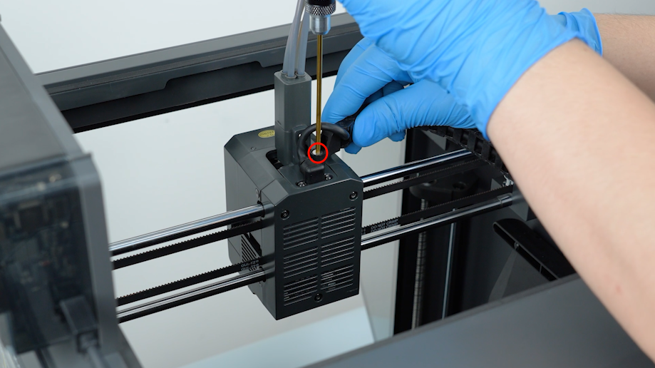
- Plug in the extruder communication cable and tighten the screws. Secure the extruder communication cable.
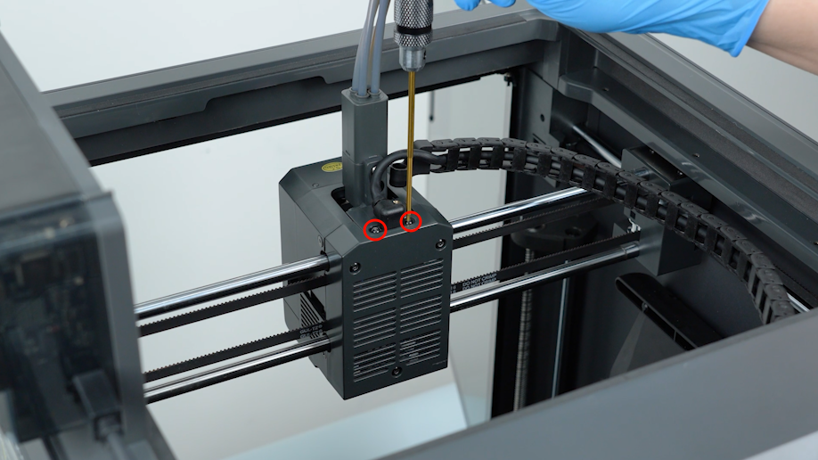
- Put the drag chain in the installation position. Tighten the screws securing the drag chain.
¶ Verification
¶ Load the Filament
-
Plug in the power supply cable. Turn the power switch ON (symbol |).
-
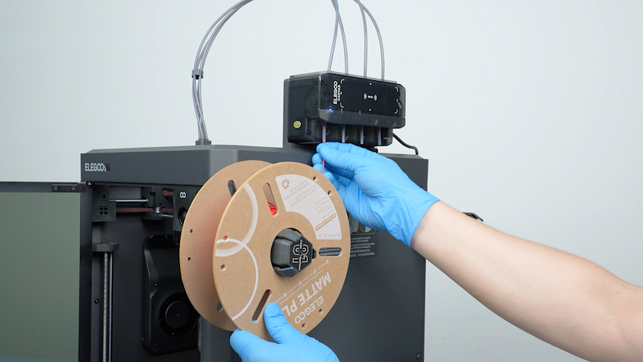
Install the filament into the spool. Feed the filament into the PTFE tube of the CANVAS.
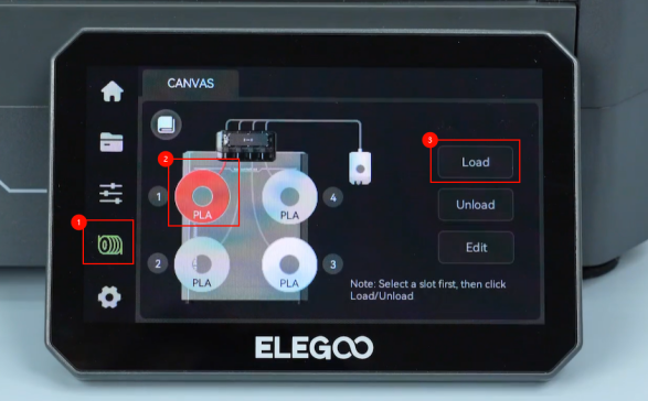
- On the touch screen, select Filament - Spool - Load.
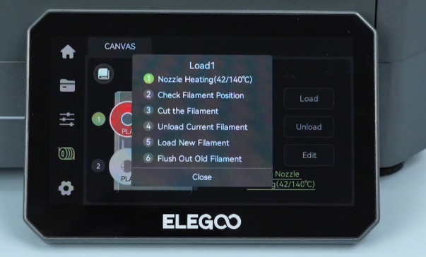
- After loading the filament, check whether the filament can be extruded normally.
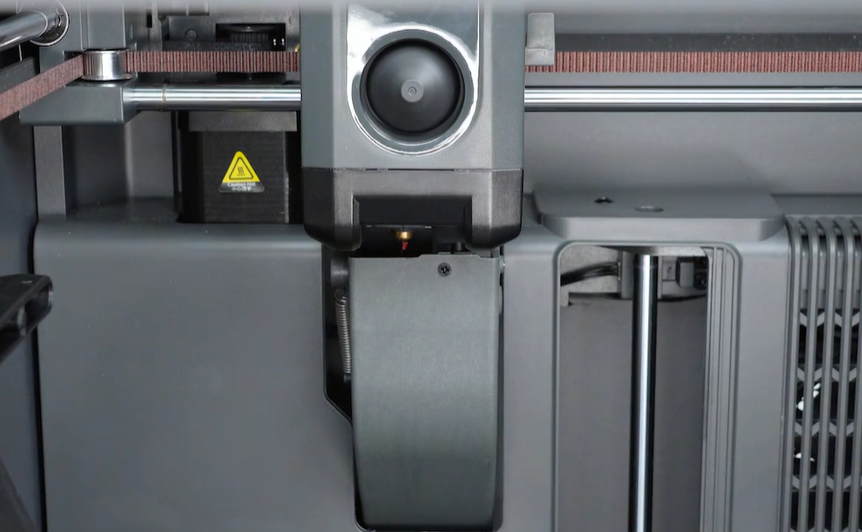
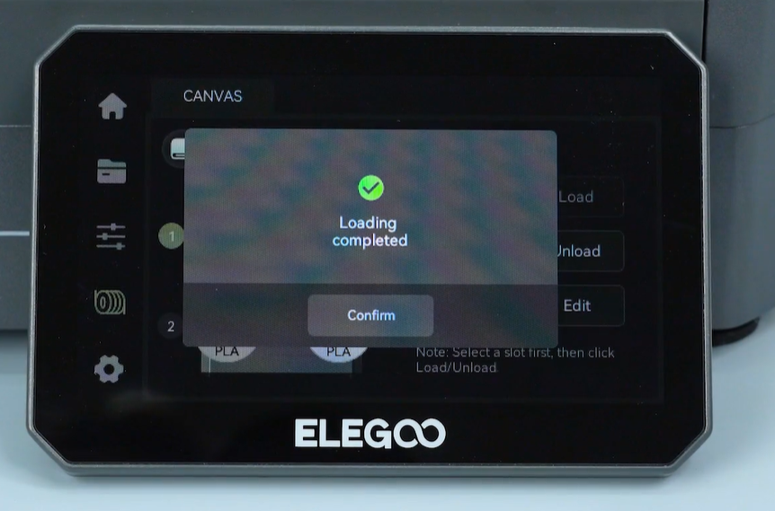
- Confirm that the filament can be extruded normally, and then tap Confirm.
¶ Run Self-check
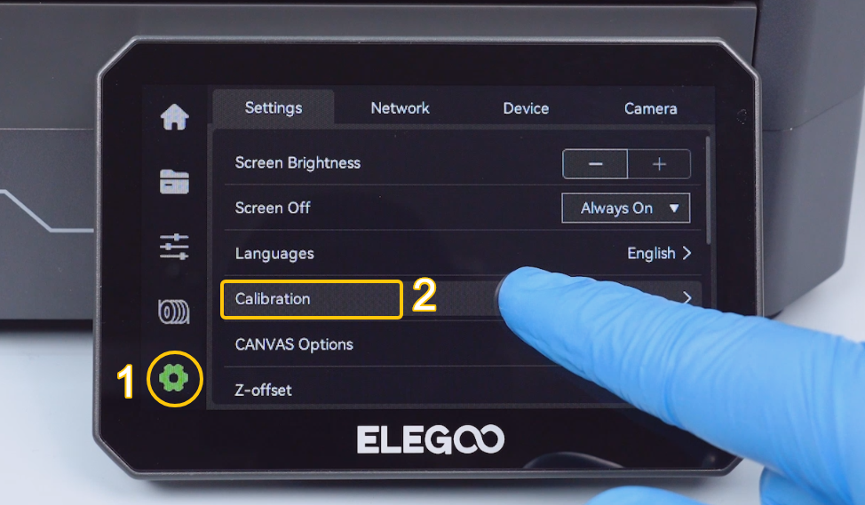
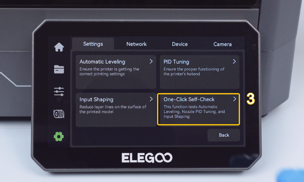
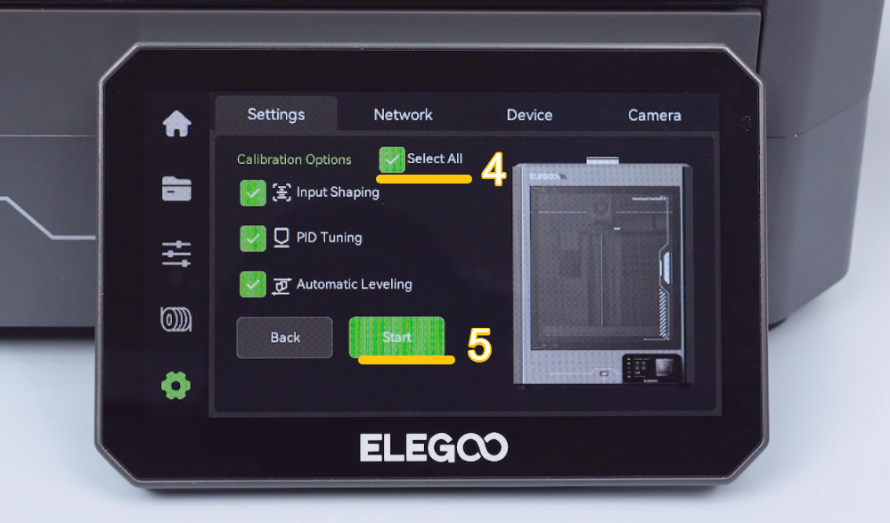
- On the touch screen, select Settings - Calibration - One-Click self-check - All - Start. The printer is ready for use after the self-check is complete.
¶ Help us improve
If you have any ideas about the wiki pages, please let us know via ELEGOO official feedback channel.