¶ Operation Steps for Each Model
The steps below are based on Centauri Carbon 2 Combo. For other models, skip the steps related to parts that are not installed.
| Model | Action | Steps to Skip |
|---|---|---|
| Centauri Carbon 2 Combo | Follow all steps | None |
| Centauri Carbon 2 | Skip CANVAS-related steps |
|
| Centauri 2 Combo | Skip enclosure-related steps only if the enclosure is not installed |
|
| Centauri 2 | Skip CANVAS-related steps |
|
If your printer has optional accessories installed, such as CANVAS or an enclosure, follow the steps related to those parts.
¶ Tools and Materials
-
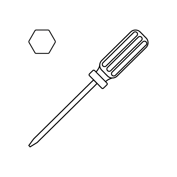
A 2.0 mm Allen key
-
A 2.5 mm Allen key
-
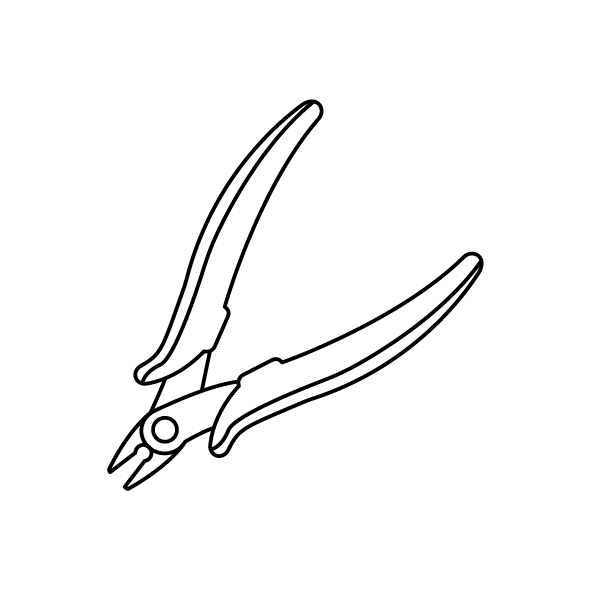
A pair of pliers
-
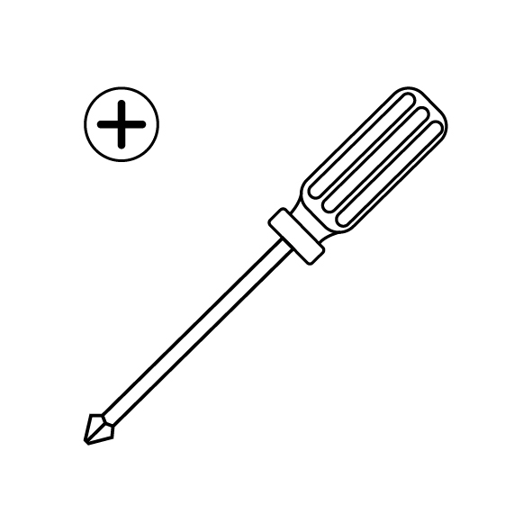
A Phillips screwdriver
-
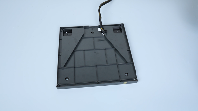
A new heated bed
¶ Tutorial Video
¶ Intruction
¶ Preparation
-
Plug in the power supply cable. Turn the power switch ON (symbol "|").
-
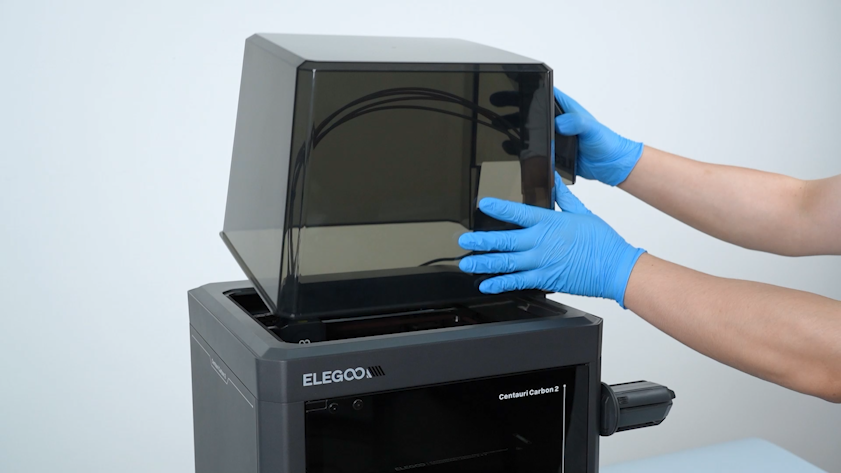
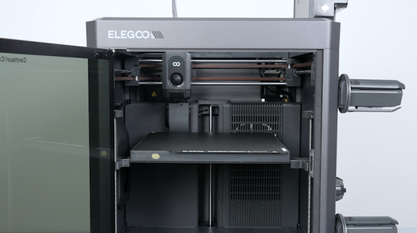
Remove the lid.
-
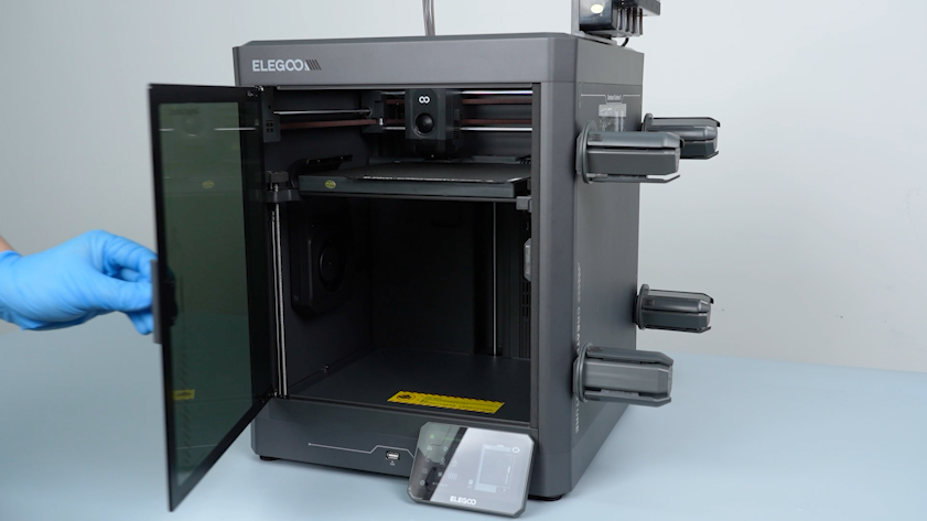
Open the front glass door.
-
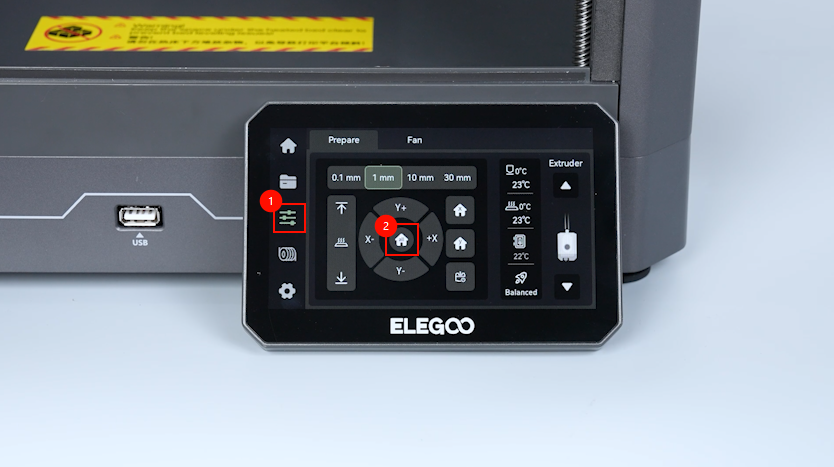
On the touch screen, select Control - Homing.
-
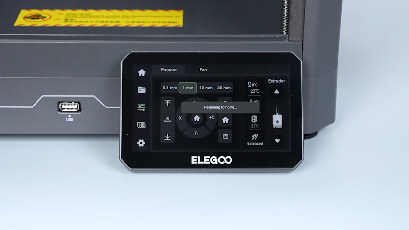
Wait for the homing process of the tool head to complete.
-
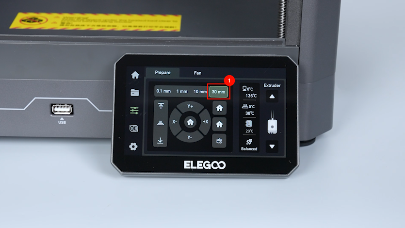
On the touch screen, select 30 mm as the motor movement distance.
-
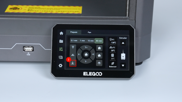
On the touch screen, select ↓ to lower down the heated bed by 60 mm.
-
Turn the power switch OFF (symbol "〇"). Unplug the power supply cable.
-
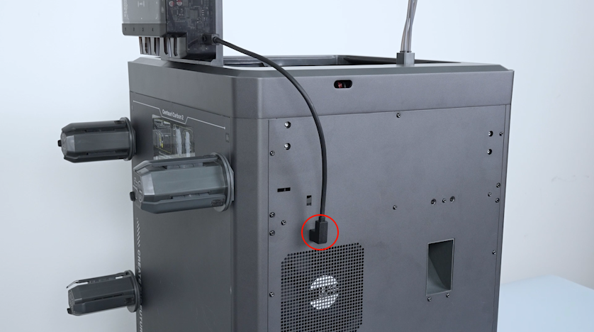
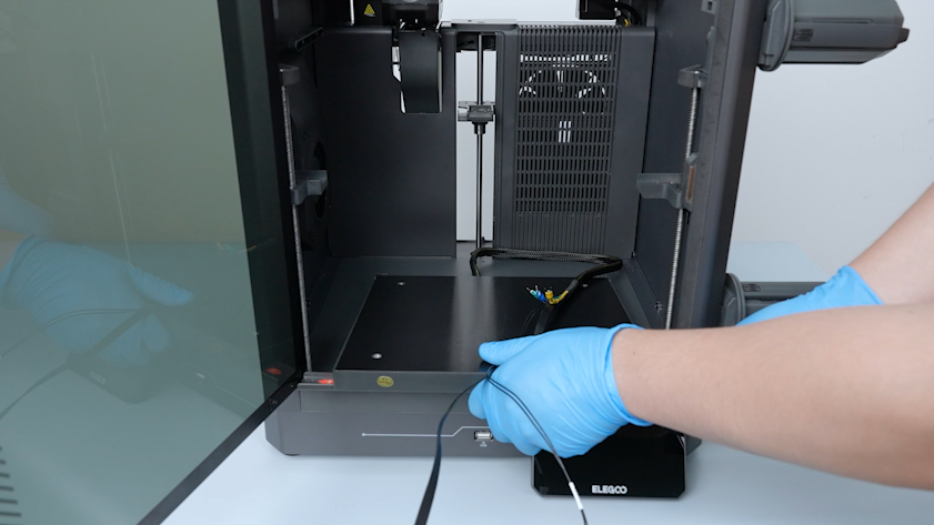
Unplug the CANVAS communication cable.
¶ Remove the bottom cover and the back cover
-
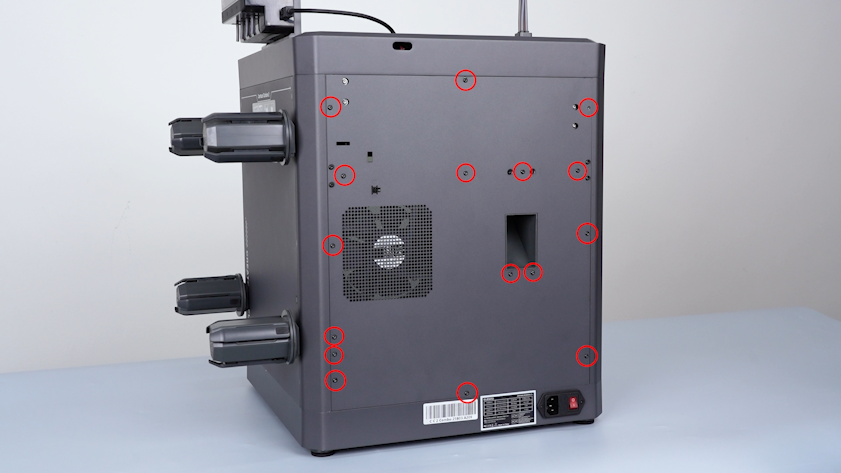
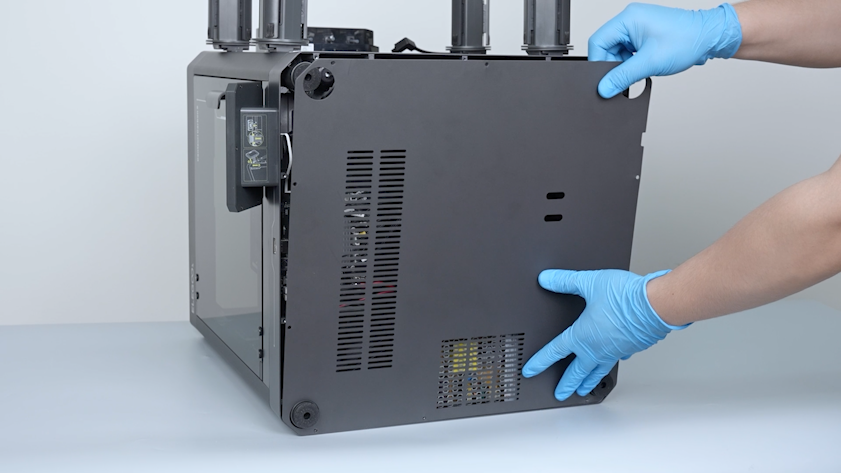
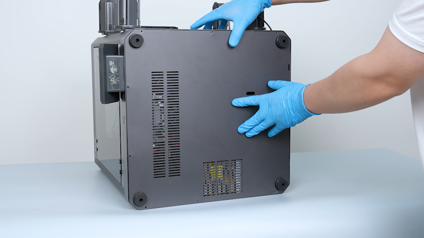
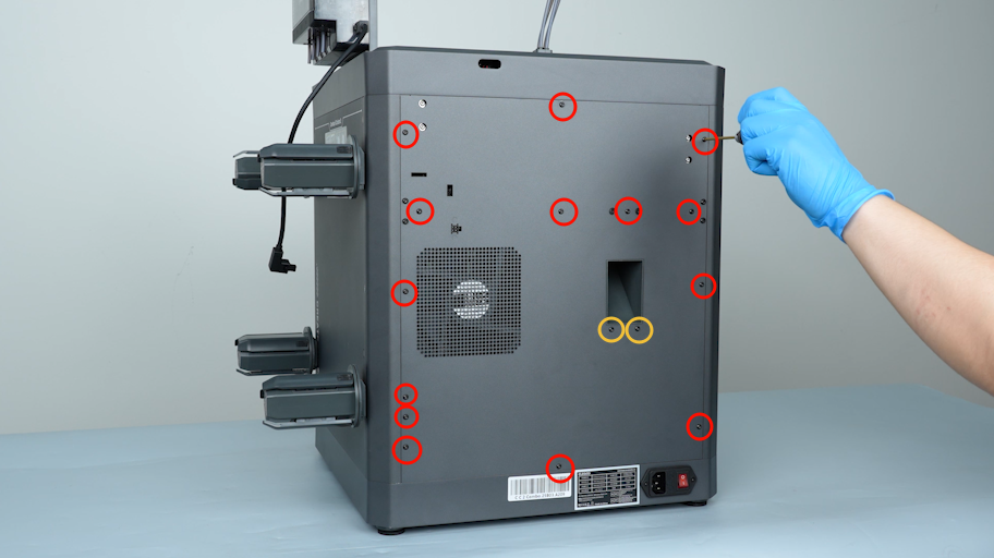
Release and remove the sixteen screws securing the back cover with a 2.0 mm Allen key.
-
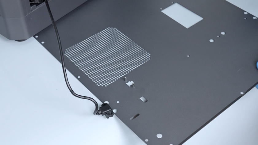
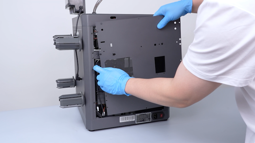
Carefully open the back cover and remove the CANVAS extension cable from the gap on the chamber cooling fan side.
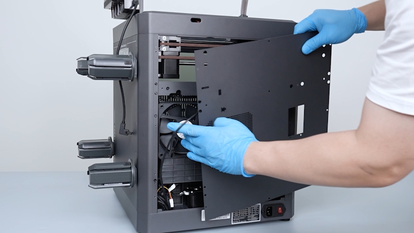
-
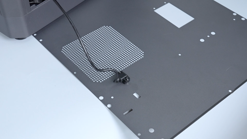
Lay the back cover flat on the table.
-
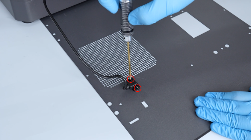
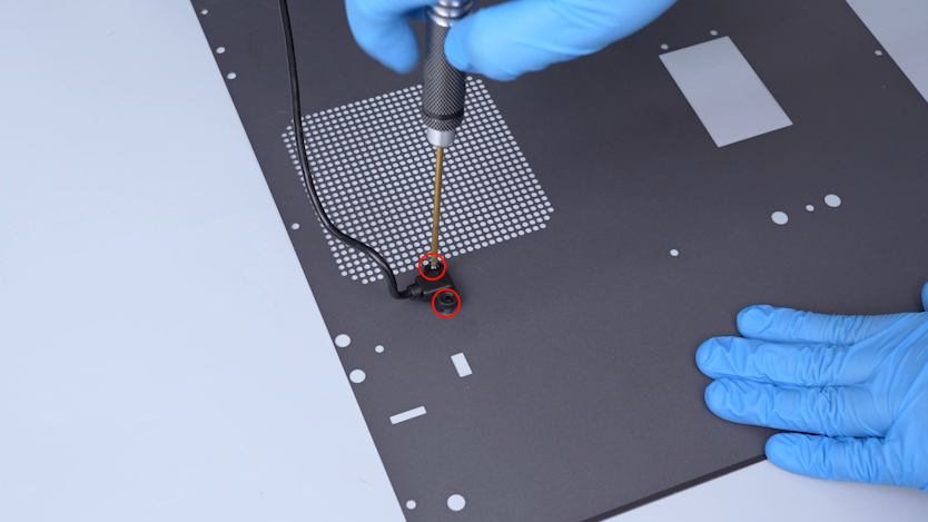
Release and remove the screws securing the CANVAS extension cable with a 2.0 mm Allen key.
-
Remove the CANVAS extension cable and the back cover.
-
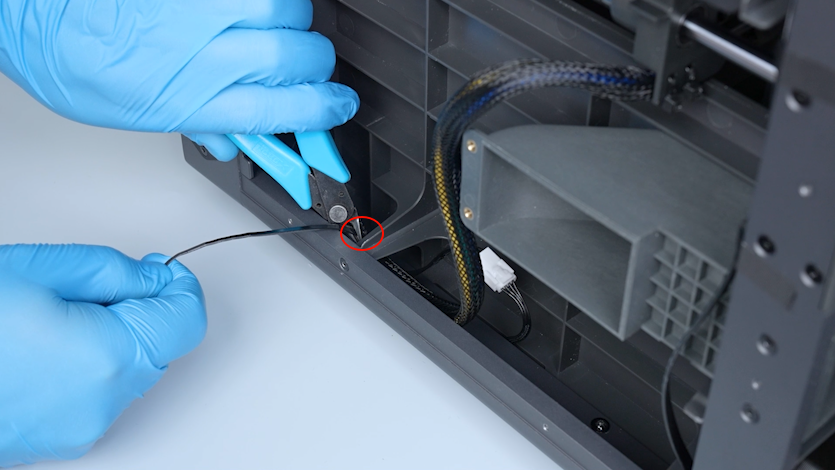
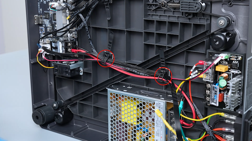
Cut off the cable ties securing the heated bed cable a pair of pliers.
-
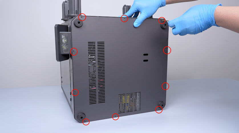
Release and remove the ten screws securing the bottom cover with a 2.0 mm Allen key.
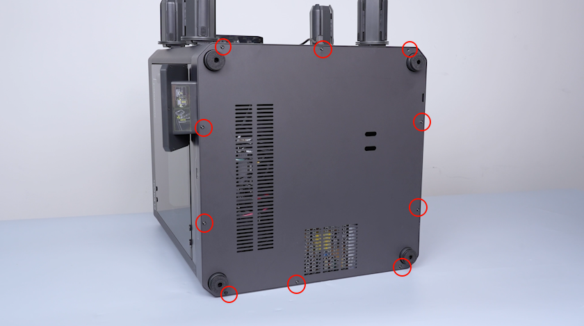
-
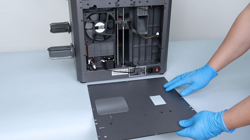
Remove the bottom cover.
¶ Pull out the heated bed wires
-
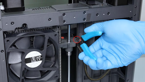
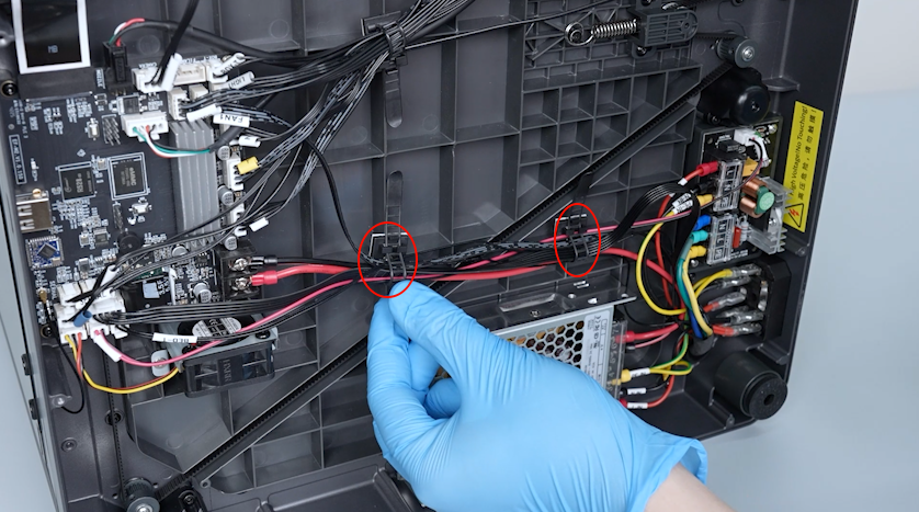
Release the two cable ties securing the wire.
-
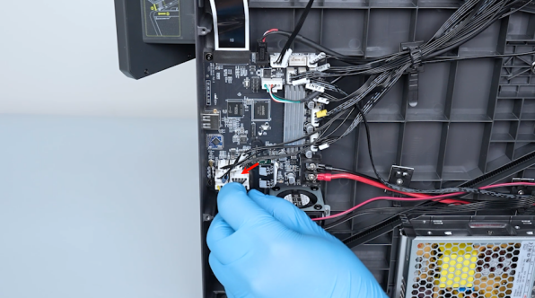
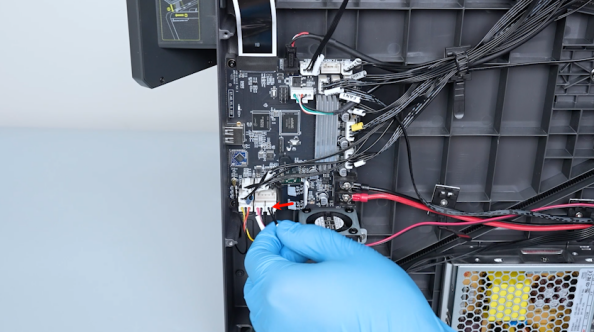
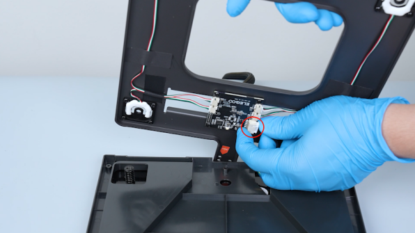
Unplug the cables of the pressure sensor and the heated bed thermistor.
-
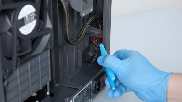
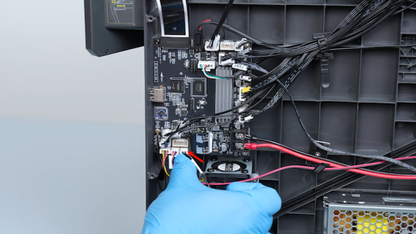
Open the heated bed control board cover.
-
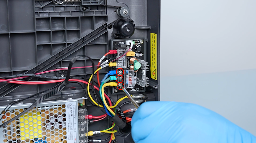
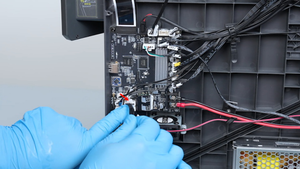
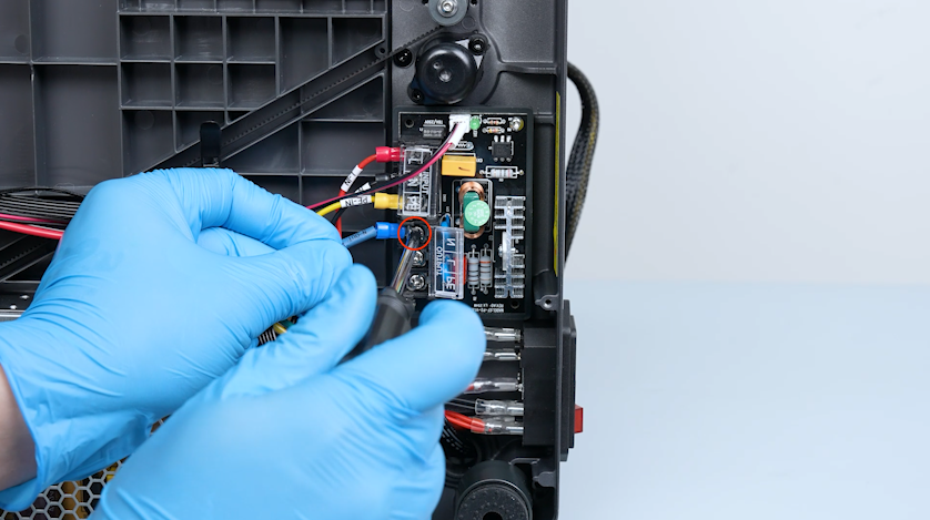
Loosen the screws securing the heated bed wires with a Phillips screwdriver.
-
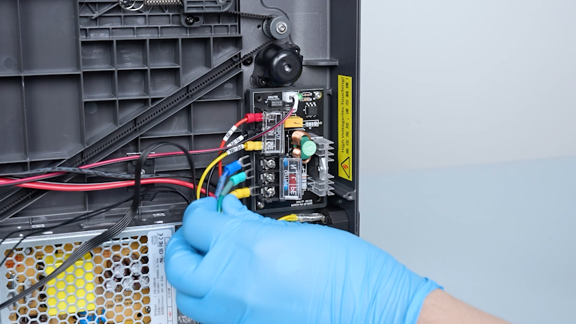
Unplug the heated bed wires.
-
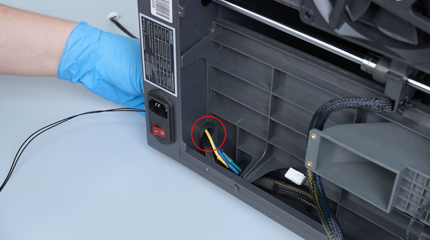
Pull the heated bed wires out through the base hole.
¶ Remove the old heated bed
-
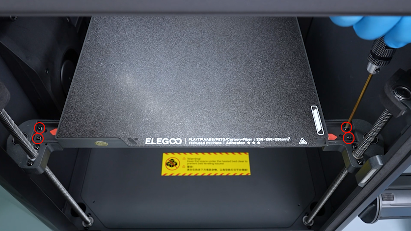
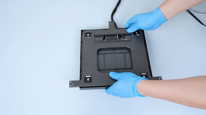
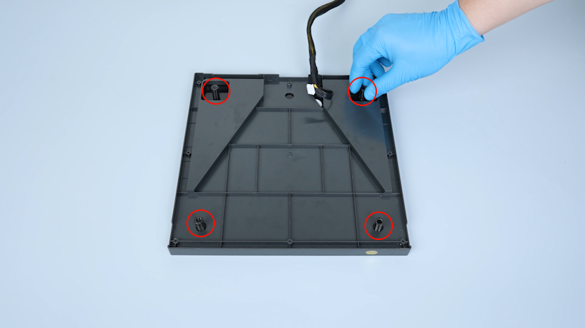
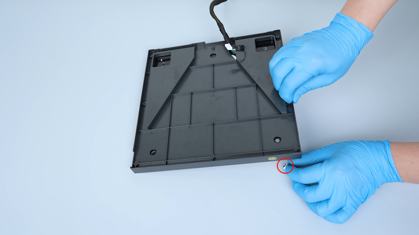
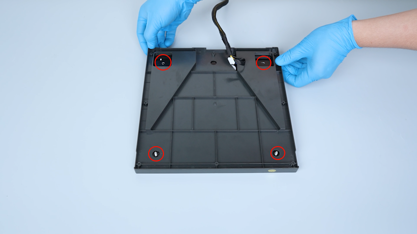
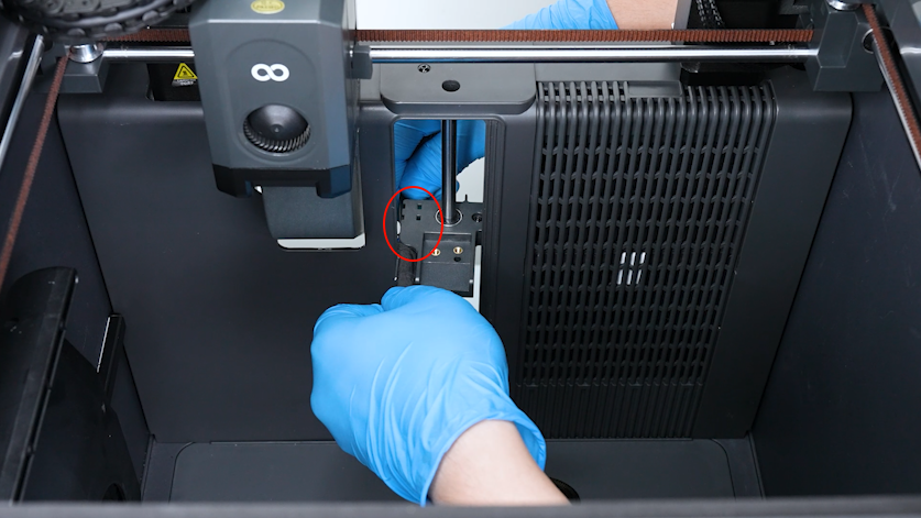
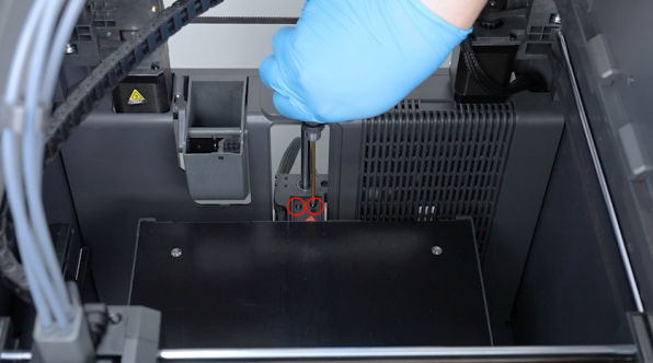
Release and remove the six screws securing the heated bed pallet with a 2.0 mm Allen key.
-
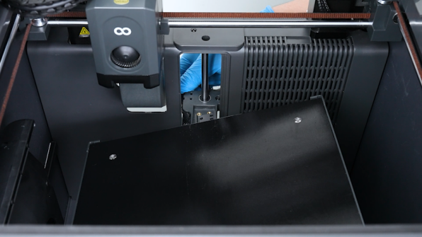
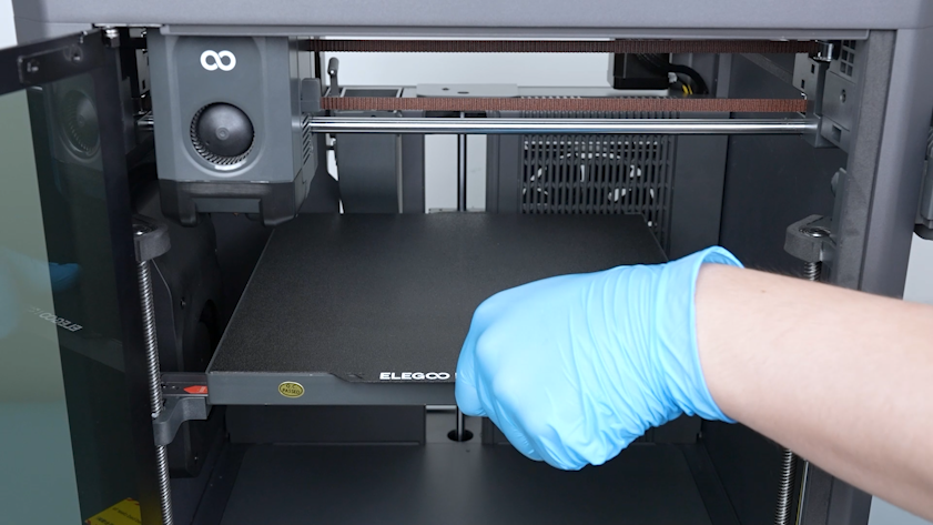
Remove the heated bed and place it temporarily at the bottom of the chamber.

-
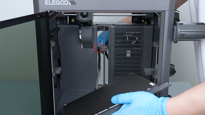
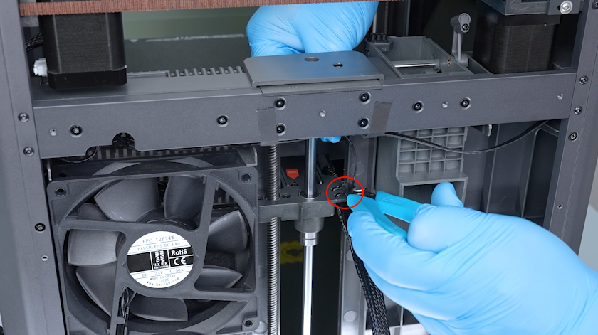
Pull the heated bed cable out of the fixation slot of the build plate connection unit behind the Z axis.
-
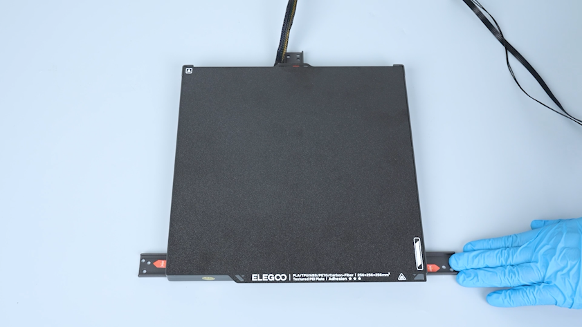
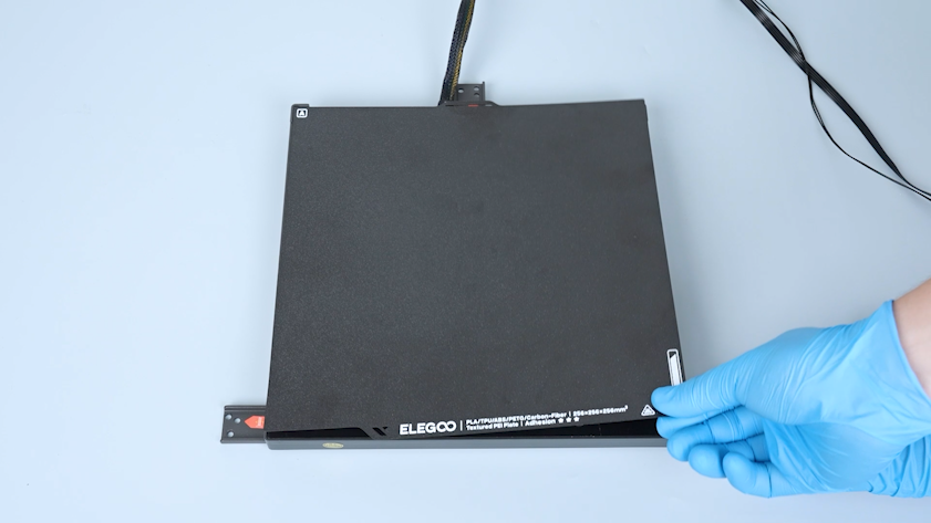
Lay the heated bed flat on the table.
-
Remove the PEI plate.
-
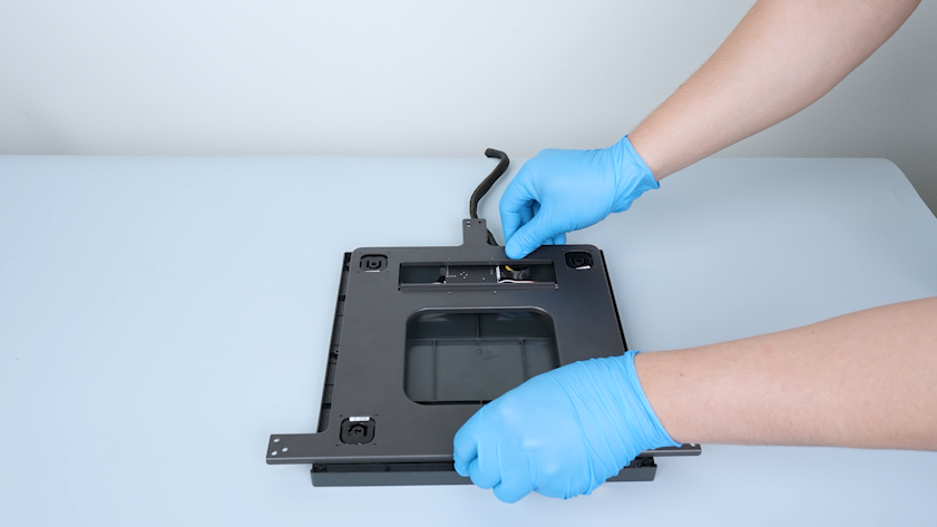
Turn the heated bed over.
-
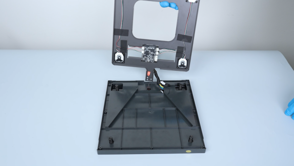
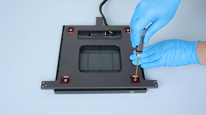
Release and remove the four screws securing the heated bed with a 2.5 mm Allen key.
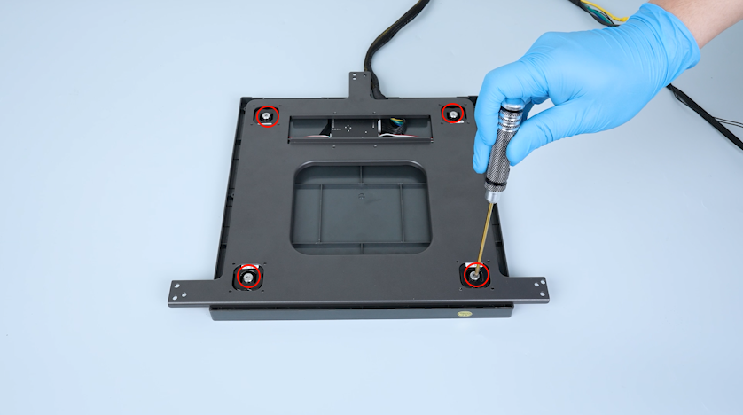
-
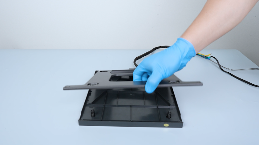
Lift the heated bed pallet.
-
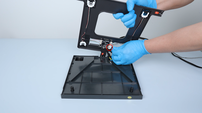
Unplug the connection wire of the pressure sensor.
-
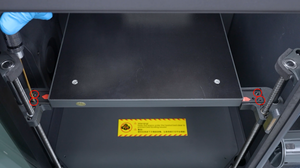
Remove the four springs and four screws.
¶ Install the new heated bed
-
Prepare the new heated bed and lay it flat on the table.
-
Put the four screws in the installation position.
-
Put the four springs in the installation position.
-
Prepare the heated bed pallet and plug in the connection wire of the pressure sensor.
-
Lay the heated bed pallet flat.
-
Secure the four screws slightly. After the screws are secured, tighten the four screws securely.
-
Put the heated bed at the bottom of the chamber.
-
Pull the heated bed cable through the fixation slot of the build plate connection unit behind the Z axis.
-
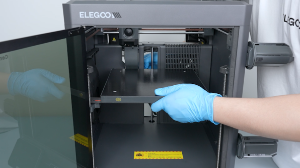
Put the heated bed on the connection units of the Z-axis build plate.
-
Tighten the six screws securing the heated bed pallet.
-
Put the PEI plate on the heated bed.
¶ Install the heated bed wires
-
Secure the heated bed cable with cable ties. Cut off the excess parts of the cable ties and remove them.
-
Pass the heated bed wires through the partition gap.
-
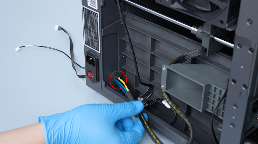
Pass the heated bed wire through the base hole.
-
Secure the wires with cable ties.
-
Plug in the pressure sensor connection wire and the heated bed thermistor cable.
-
Organize the wires and secure the cable ties.
-
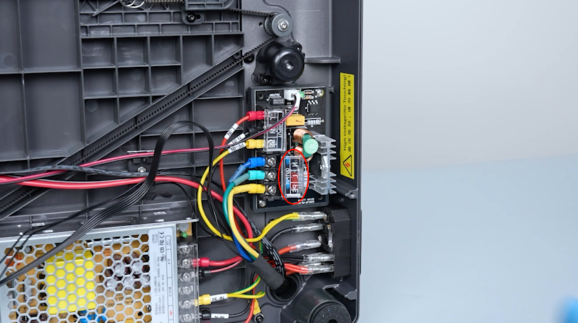
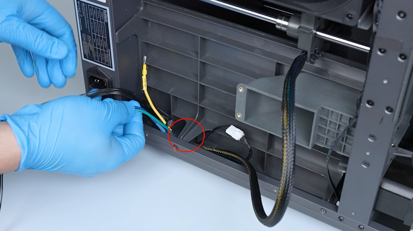
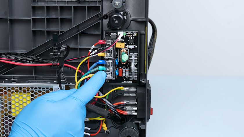
Connect the N-OUT blue wire to the OUTPUT-N port on the heated bed control board and tighten the securing screw.
-
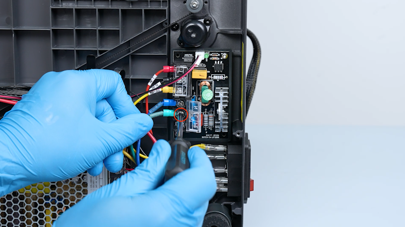
Connect the L-OUT green wire to the OUTPUT-L port on the heated bed control board and tighten the securing screw.
-
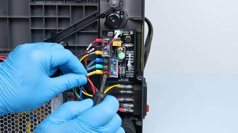
Connect the PE-OUT yellow wire to the OUTPUT-PE port on the heated bed control board and tighten the securing screw.
-
Close the heated bed control board cover.
¶ Install the bottom cover and the back cover
-
Put the bottom cover in the installation position.
-
Tighten the ten screws securing the bottom cover.
-
Put the back cover on the table.
-
Plug the CANVAS extension cable into the back cover and tighten the two screws.
-
Lift the back cover and put the CANVAS extension cable into the gap on the chamber cooling fan side.
-
Close the back cover.
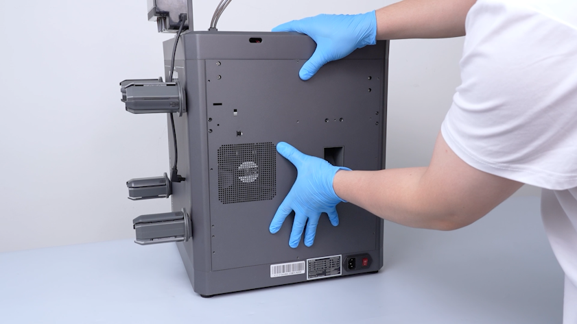
-
Tighten the sixteen screws securing the back cover.
Note: Screws labeled by the red circle are M3 x 4. Screws labeled by the yellow circle are M3 x 8.
-
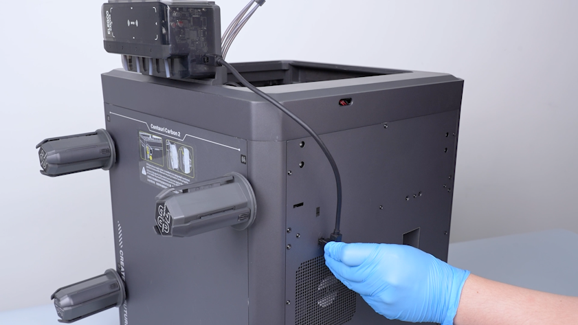
Plug the CANVAS communication cable into the back cover.
¶ Verification
-
Plug in the power supply cable. Turn the power switch ON (symbol "|").
-
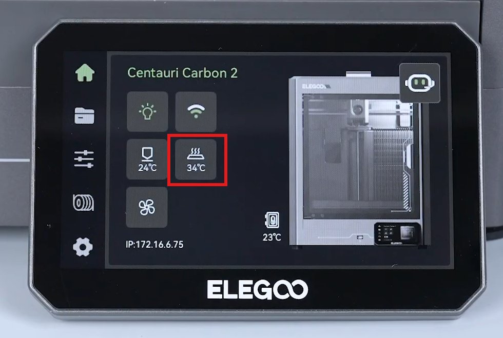
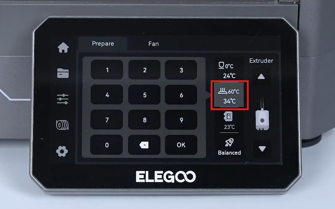
Heat the heated bed up via the touch screen to confirm that the heated bed can be heated up normally.
-
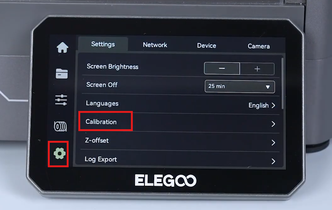
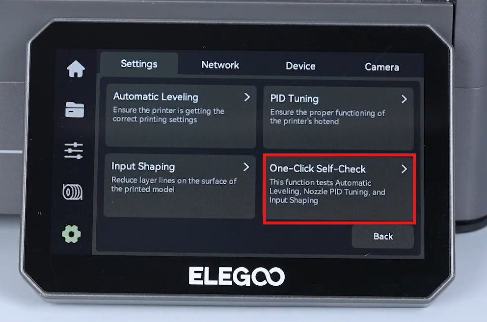
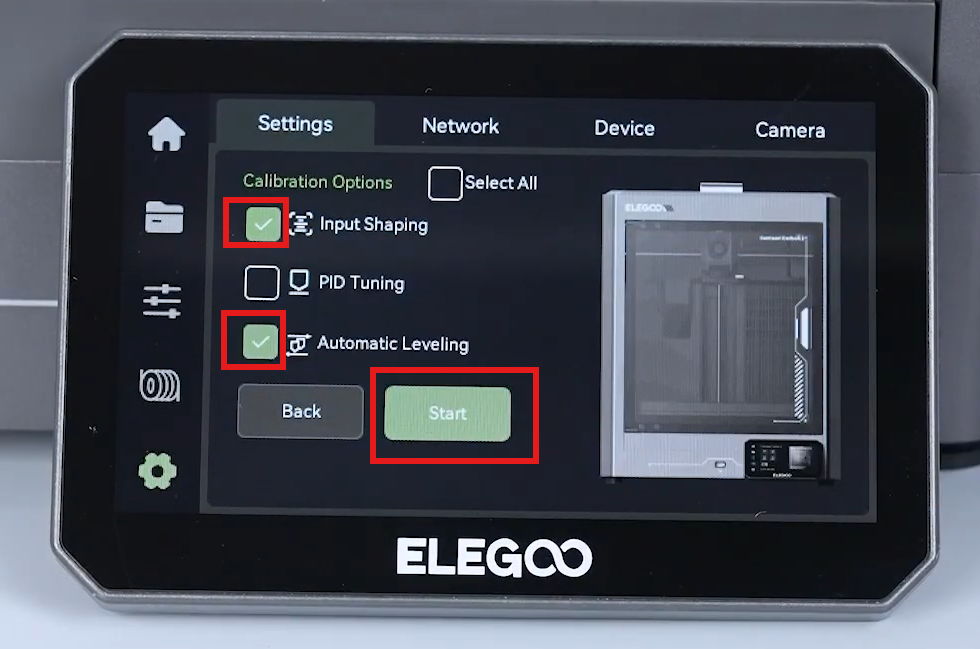
On the touch screen, select Settings - Calibration - One click self check - Input shaping - Auto leveling - Start.
-
The printer is ready for use after self-check.
¶ Help us improve
If you have any ideas about the wiki pages, please let us know via ELEGOO official feedback channel