¶ Issue Description
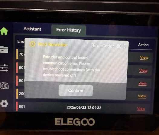
Extruder and control board communication error. Please troubleshoot connections (with thedevice powered off)
¶ Reasons
-
The Tool head communication cable has poor contact.
-
The tool head communication board is damaged.
-
The Tool head communication cable is damaged.
-
The motherboard has a malfunction.
¶ Tools needed for troubleshooting
-
A 2.0 mm Allen key
-
A multimeter
¶ Troubleshooting Steps
¶ Step 1 Re-plug Tool head communication cable connected to the tool head.
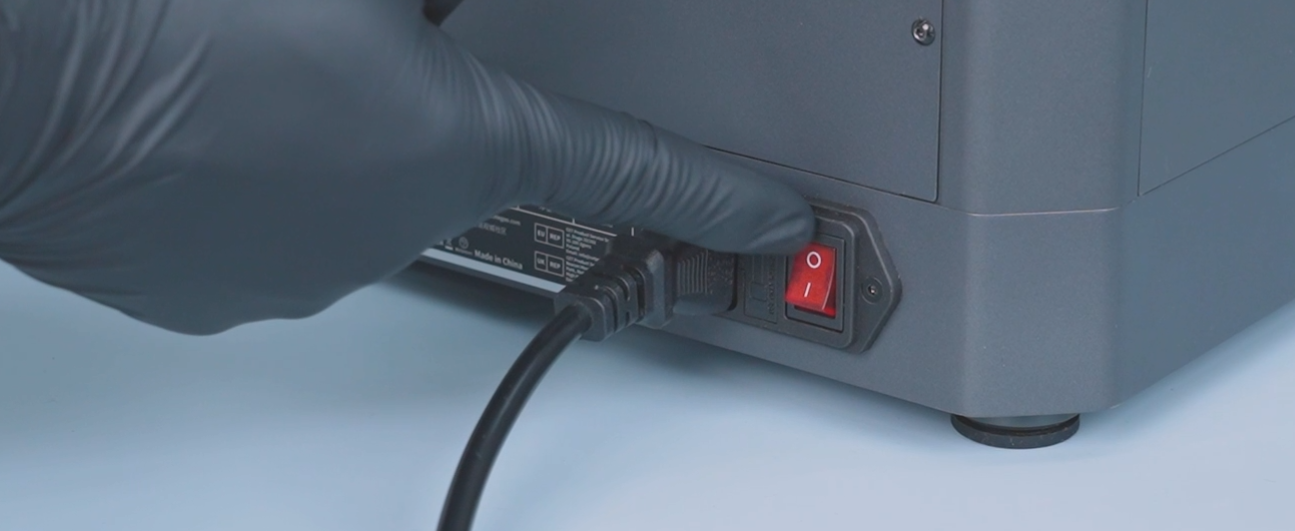
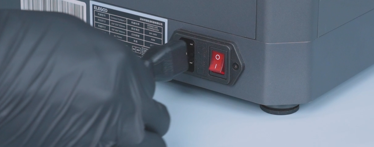
- Turn the power switch OFF (symbol "〇") and unplug the power supply cable.
-
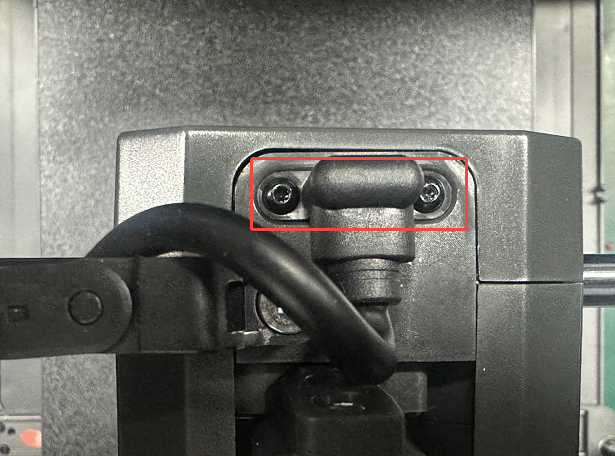
Remove the two screws securing the Tool head communication cable.
-
Re-plug the Tool head communication cable.
¶ Step 2 Re-plug the Tool head communication cable connected to the motherboard.
-
Turn the power switch OFF (symbol "〇") and unplug the power supply cable.
-
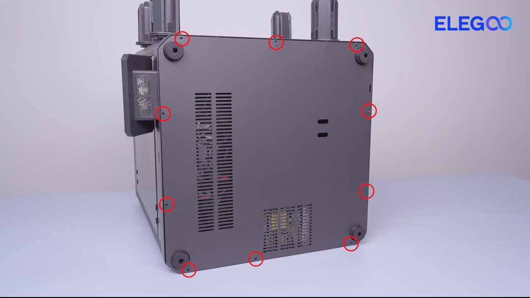
Remove the ten screws securing the bottom cover with a 2.0 mm Allen key and remove the cover.
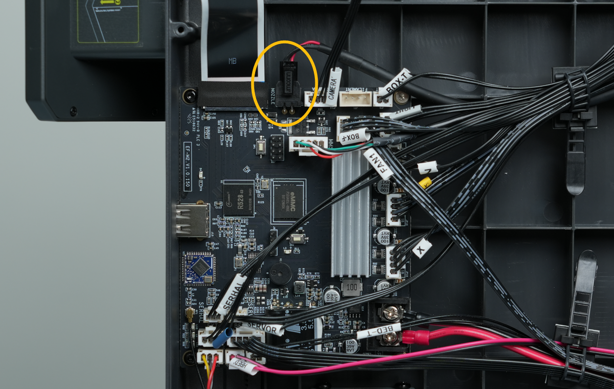
- Re-plug the extruder Tool head communication cable connected to the motherboard.
¶ Step 3 Check whether the forward voltage of the tool head communication board is within the normal range.
-
Turn the power switch OFF (symbol "〇") and unplug the power supply cable.
-
Set the multimeter to the diode mode or continuity (buzzer) mode.
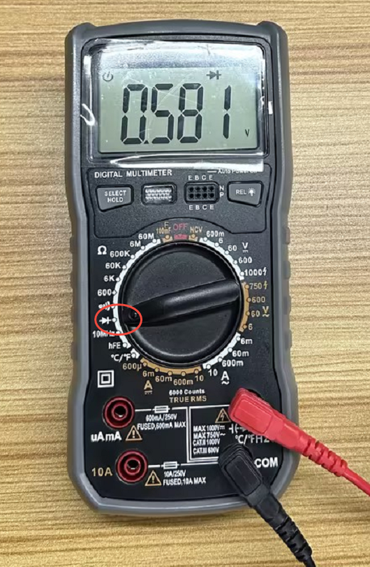
- Measure the forward voltage at the corresponding position.
Note: The normal forward voltage is approximately 0.58 V.
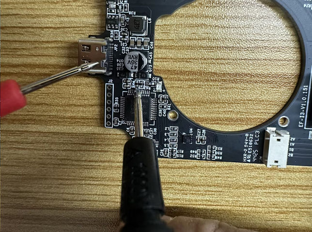
- If the measured value deviates significantly from the normal range, it indicates that the tool head communication board needs to be replaced.
¶ Step 4 Check whether the forward voltage at the corresponding position on the motherboard is within the normal range.
-
Turn the power switch OFF (symbol "〇") and unplug the power supply cable.
-
Set the multimeter to the diode mode or continuity (buzzer) mode.
-
Measure the forward voltage at the corresponding position.
Note: The normal forward voltage is approximately 0.66 V.
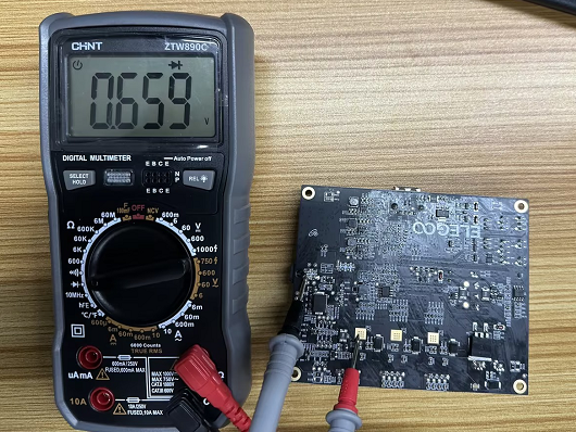
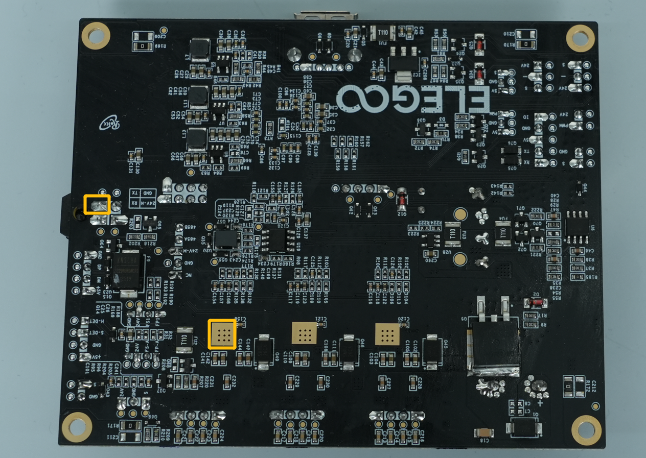
- If the measured value deviates significantly from the normal range, it indicates that the motherboard needs to be replaced.
How to Replace the Motherboard(B0C1J1) - If the measured forward voltage of both the tool head communication board and the motherboard are within the normal range, it indicates that the tool head Tool head communication cable needs to be replaced.
¶ Help us improve
If you have any ideas about the wiki pages, please let us know via ELEGOO official feedback channel