¶ Operation Steps for Each Model
The steps below are based on Centauri Carbon 2 Combo. For other models, skip the steps related to parts that are not installed.
| Model | Action | Steps to Skip |
|---|---|---|
| Centauri Carbon 2 Combo | Follow all steps | None |
| Centauri Carbon 2 | Skip CANVAS-related steps |
|
| Centauri 2 Combo | Not applicable |
|
| Centauri 2 | Not applicable |
|
If your printer has optional accessories installed, such as CANVAS or an enclosure, follow the steps related to those parts.
¶ Tools and Materials
-
1.5 mm Allen key
-
2.0 mm Allen key
-
2.5 mm Allen key
-
A new chamber thermistor
¶ Tutorial Video
¶ Instruction
¶ Preparation
-
Plug in the power supply cable. Turn the power switch ON (symbol "|") .
-
On the touch screen, select Control - Homing.
-
After the homing process, select 30 mm - ↓ on the touch screen and lower the heated bed to the bottom.
-
Turn the power switch OFF (symbol "〇"). Unplug the power supply cable.
¶ Remove the CAN Bus and CANVAS Assembly
-
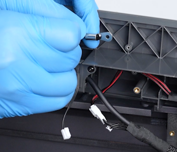
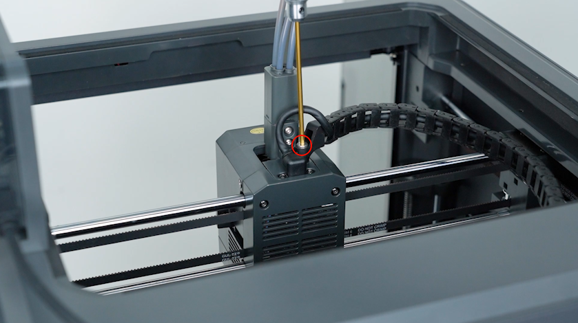
Release and remove the two screws securing the CAN bus with a 1.5 mm Allen key. Unplug the CAN bus.
-
Release and remove the screw securing the tank chain with a 2.5 mm Allen key. Remove the tank chain.
-
Release and remove the two screws securing the 4-in-1 hub with a 2.0 mm Allen key. Remove the 4-in-1 hub.
-
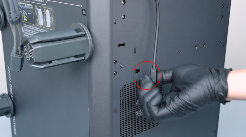
Unplug the CANVAS communication cable.
-
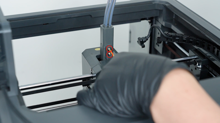
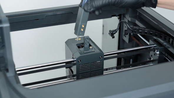
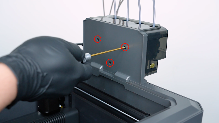
Release and remove the three screws securing the CANVAS with a 2.0 mm Allen key.
Note: Hold the CANVAS when releasing the last screw.
-
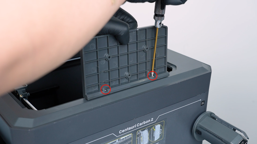
Release and remove the two screws securing the CANVAS holder with a 2.0 mm Allen key. Remove the CANVAS holder.
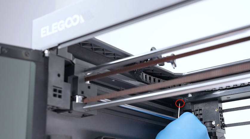
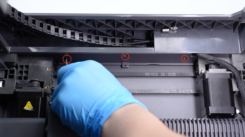
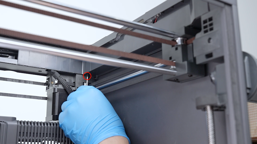
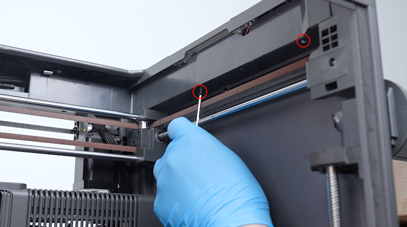
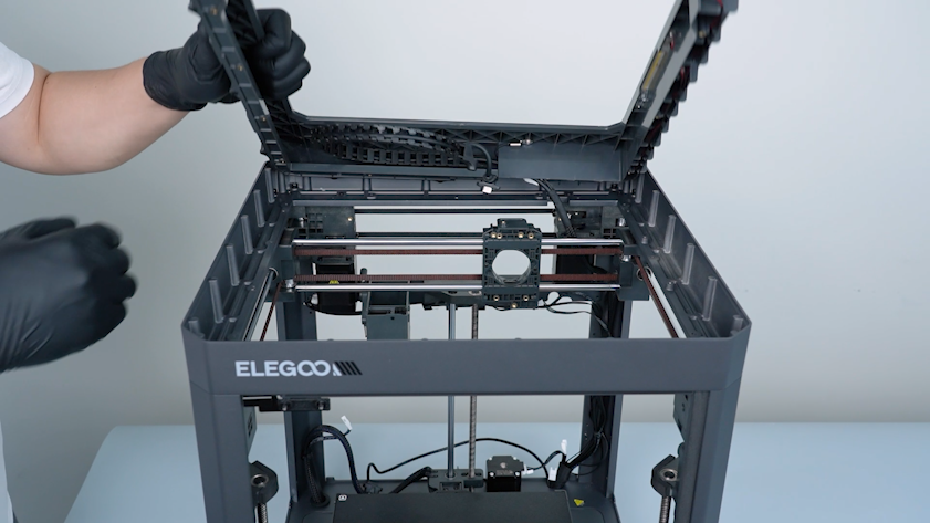
¶ Remove the Upper Frame Housing
-
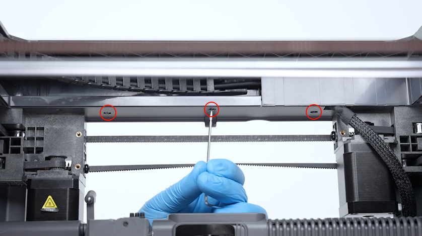
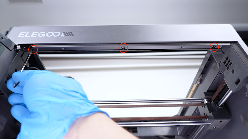
Release and remove the three screws securing the front side of the upper frame housing with a 2.0 mm Allen key.
-
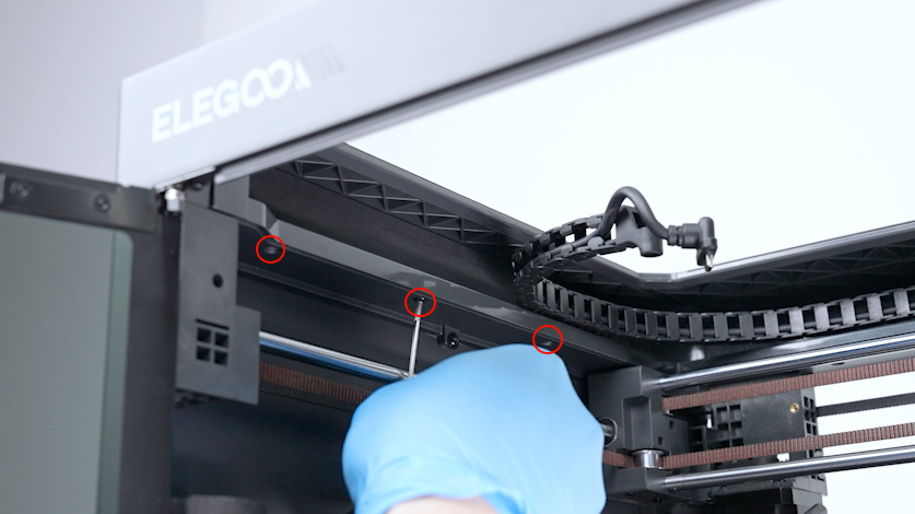
Release and remove the four screws securing the left side of the upper frame housing with a 2.0 mm Allen key.
-
Release and remove the three screws securing the back side of the upper frame housing with a 2.0 mm Allen key.
-
Release and remove the three screws securing the right side of the upper frame housing with a 2.0 mm Allen key.
-
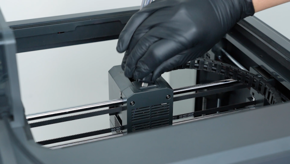
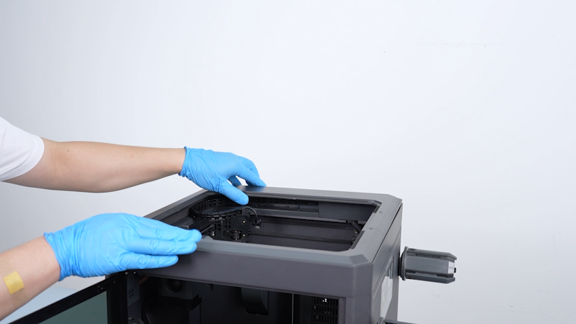
Lift the upper frame housing.
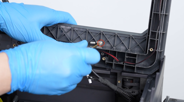
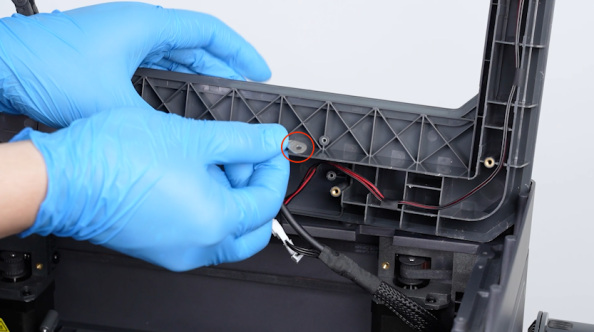
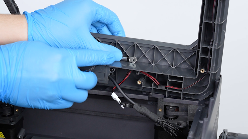
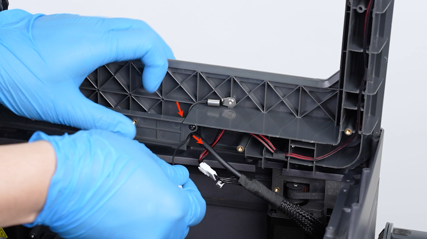
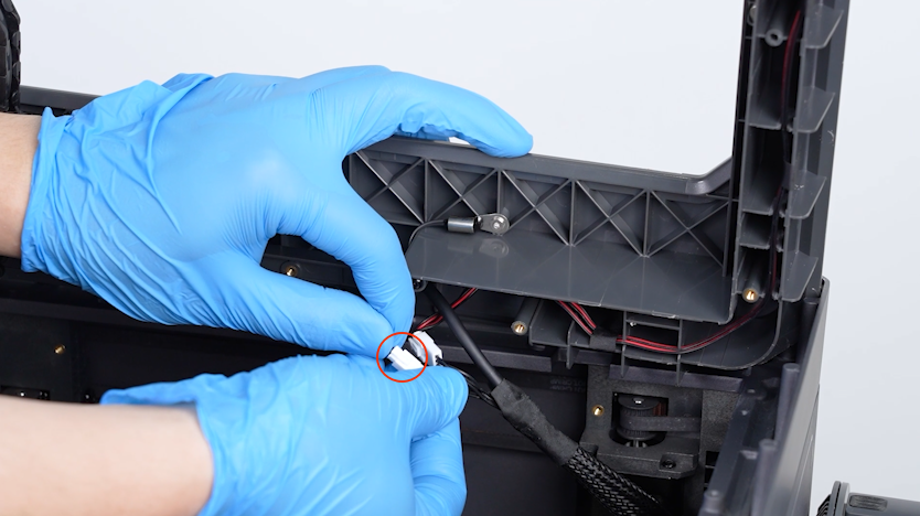
¶ Remove the Old Chamber Thermistor
-
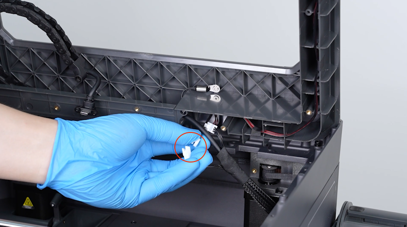
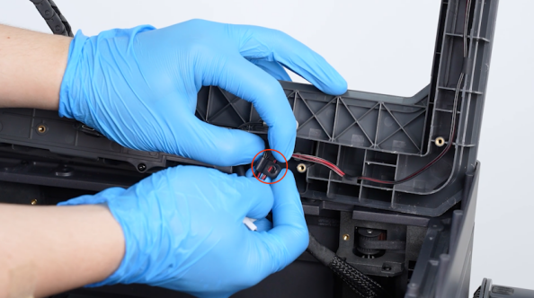
Remove the plug of the chamber thermistor.
-
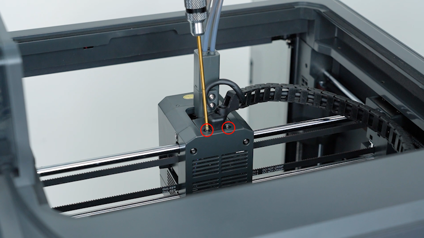
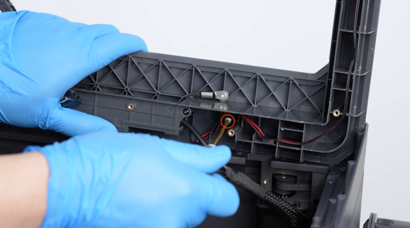
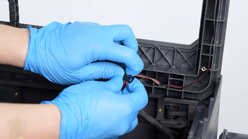
Release and remove the screw securing the clip with a 2.0 mm Allen key. Remove the clip.
-
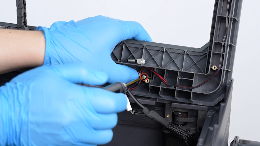
Release and remove the screw securing the chamber thermistor with a 2.0 mm Allen key. Remove the chamber thermistor.
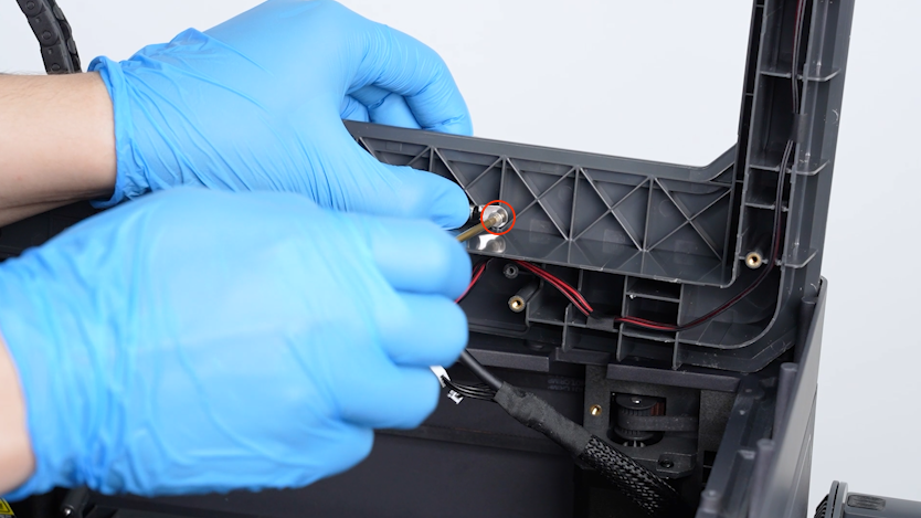
¶ Install the Chamber Thermistor
-
Get the new chamber thermistor and put it in the installation position.
-
Tighten the screw securing the chamber thermistor.
-
Pass the chamber thermistor wire through the groove in the upper frame housing.
-
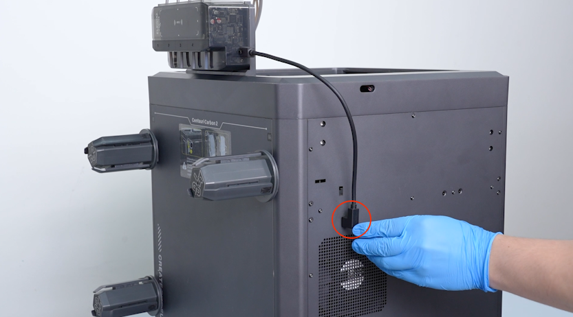
Insert the chamber thermistor plug into the port.
-
Secure the wires with the clip.
-
Put the clip in the installation position and tighten the screw securing the clip with a 2.0 mm Allen key.
¶ Reinstall the Upper Frame Housing
-
Install the upper frame.
-
Tighten the three screws securing the front of the upper frame housing.
-
Tighten the four screws securing the left side of the upper frame housing.
-
Tighten the three screws securing the back side of the upper frame housing.
-
Tighten the three screws securing the right side of the upper frame housing.
¶ Reinstall the CANVAS Assembly
-
Put the CANVAS holder in the installation position and tighten the two screws securing the CANVAS holder.
-
Put the CANVAS in the installation position and tighten the three screws securing the CANVAS.
-
Plug in the communication cable of the CANVAS.
-
Install the 4-in-1 hub and tighten the two screws securing the 4-in-1 hub.
-
Plug in the CAN bus and tighten the two screws securing the CAN bus with a 1.5 mm Allen key.
-
Put the tank chain in the installation position and tighten the screw securing the tank chain.
¶ Check Chamber Temperature Detection
-
Plug in the power supply cable. Turn the power switch ON (symbol "|").
-
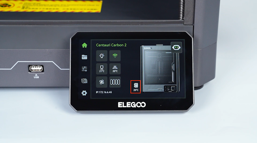
Confirm that the temperature of the chamber on the touch screen is the same as the room temperature.
-
The chamber thermistor is replaced successfully.
¶ Help us improve
If you have any ideas about the wiki pages, please let us know via ELEGOO official feedback channel