¶ Required Tools
- 3.0 mm Allen Key
- 2.5 mm Allen Key
- 2.0 mm Allen Key
- Phillips Screwdriver
- Side Cutters
- Tweezers
¶ Preparation
- Lower the heated bed to the bottom of the printer using the touch screen.
- Turn off the power switch.
- Unplug the power cord.
¶ Disassembly
¶ Remove the Back Cover
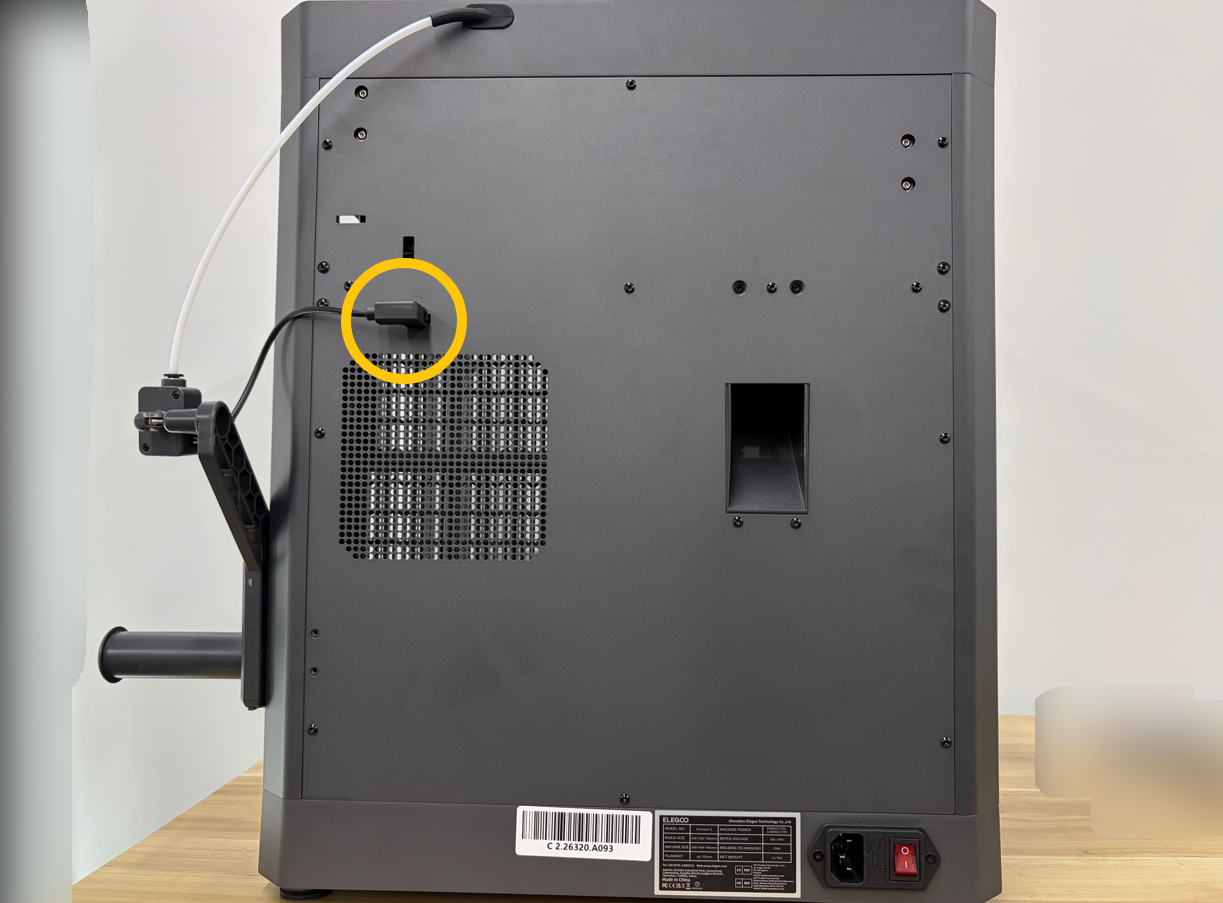
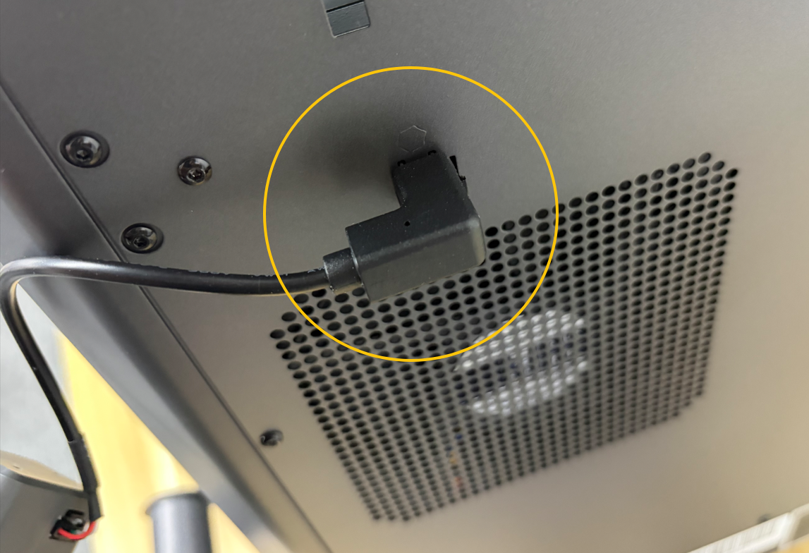
¶ Step 1. Disconnect the Filament Runout Sensor Cable
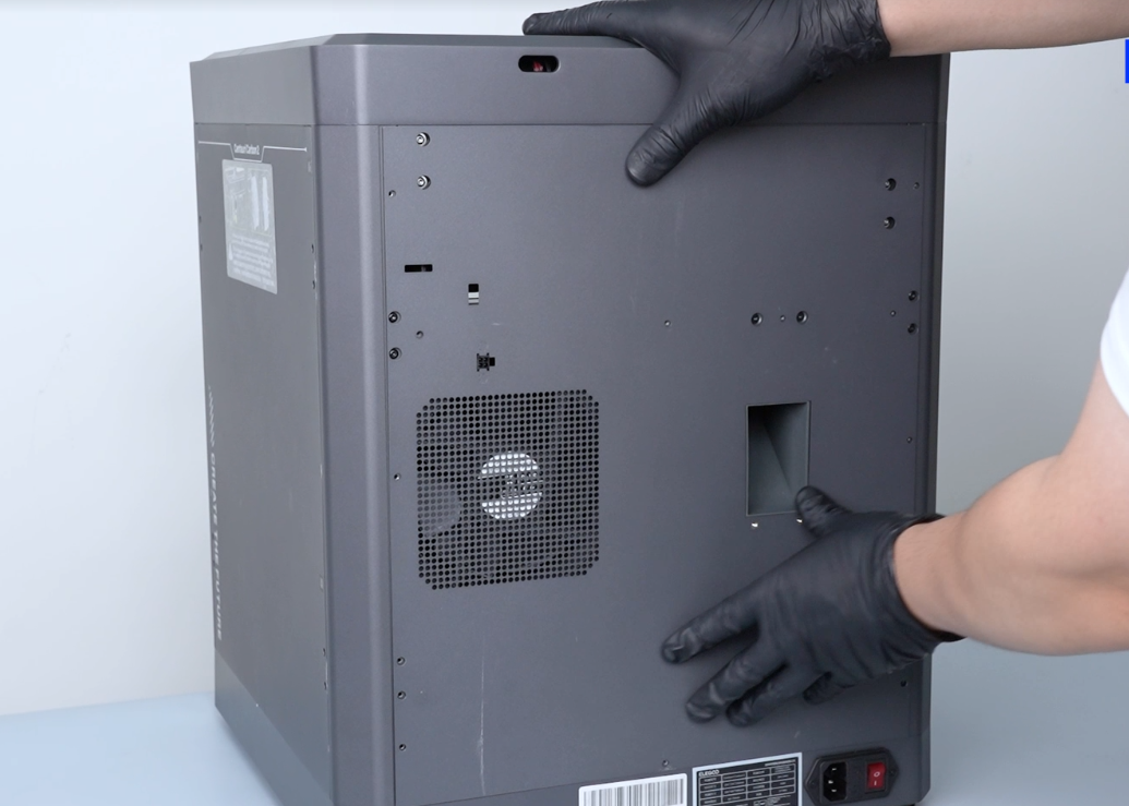
¶ Step 2. Remove the Back Cover
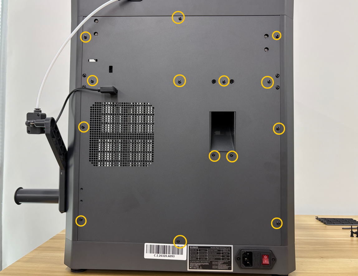
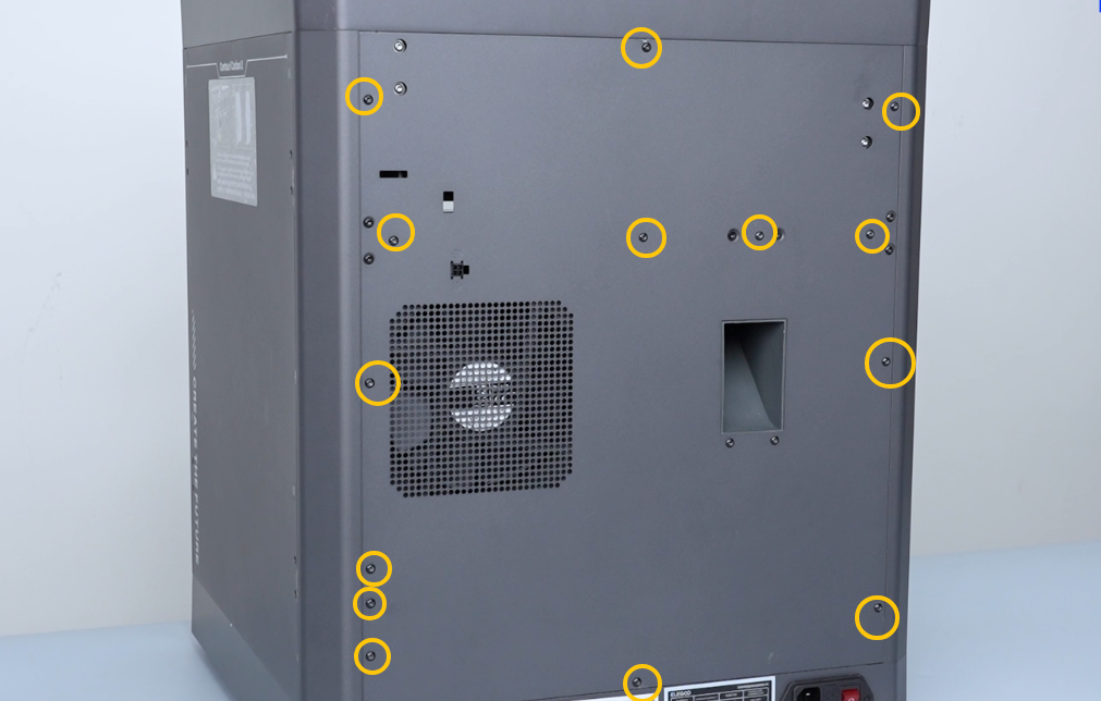
Using a 2.0 mm Allen key, remove the 14 screws securing the back cover, then slowly pull the back cover downward.
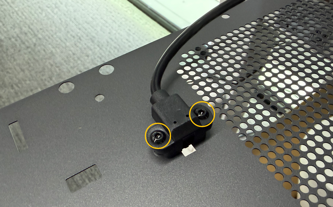
¶ Step 3. Remove the CANVAS Extension Cable Connector
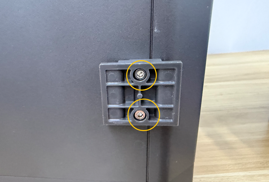
Using a 2.0 mm Allen key, remove the 2 screws securing the CANVAS Extension cable connector, then remove the connector.
¶ Remove the Upper Partition Screws
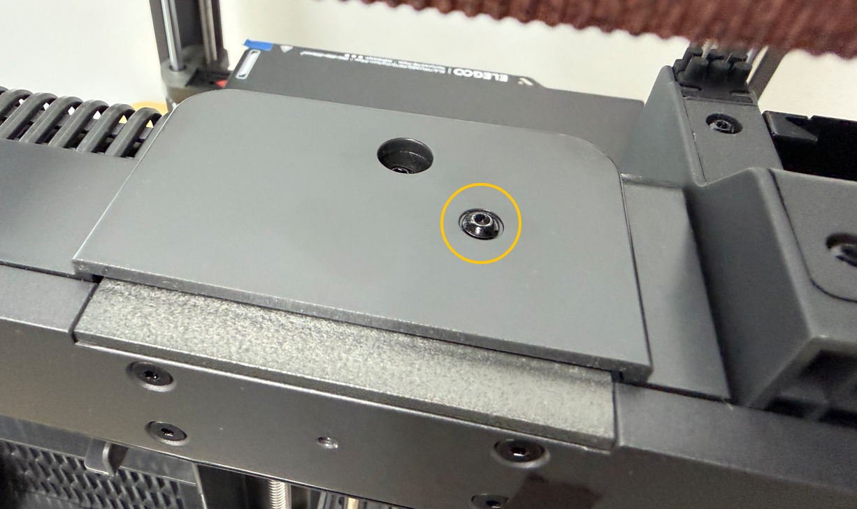
Using a 2.0 mm Allen key, remove the screws securing the upper side of the partition.
¶ Remove the Rear Partition Screws
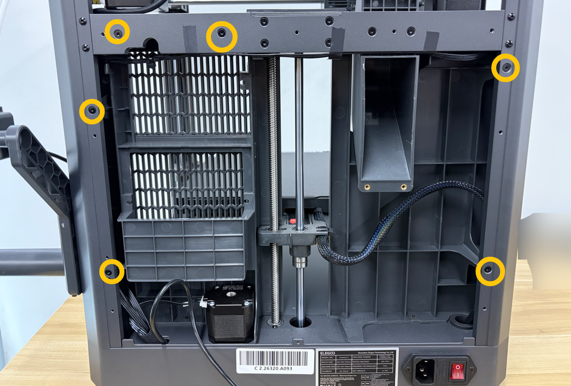
Using a 2.0 mm Allen key, remove the 6 screws securing the rear side of the partition.
¶ Remove the Bottom Cover
¶ Step 1. Position the Printer
Lay the printer on its side with the spool holders facing upward.
¶ Step 2. Remove the Bottom Cover
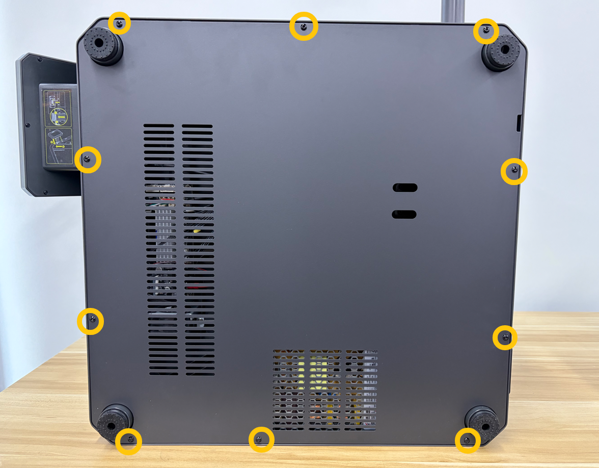
Using a 2.0 mm Allen key, remove the 10 screws securing the bottom cover, then remove the bottom cover.
¶ Remove the Lower Partition Screws
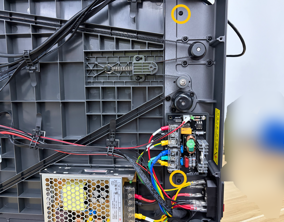
Using a 2.0 mm Allen key, remove the 2 screws securing the bottom side of the partition.
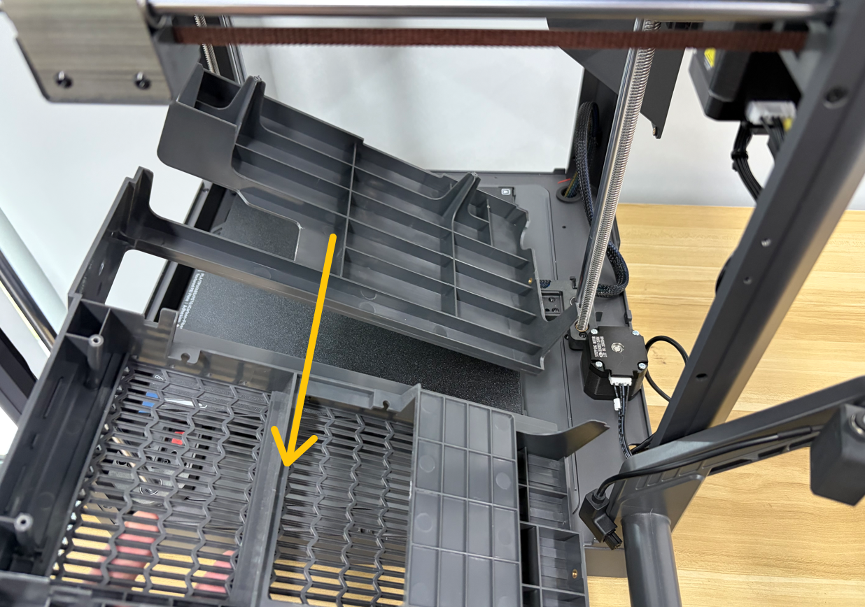
¶ Remove the Partition
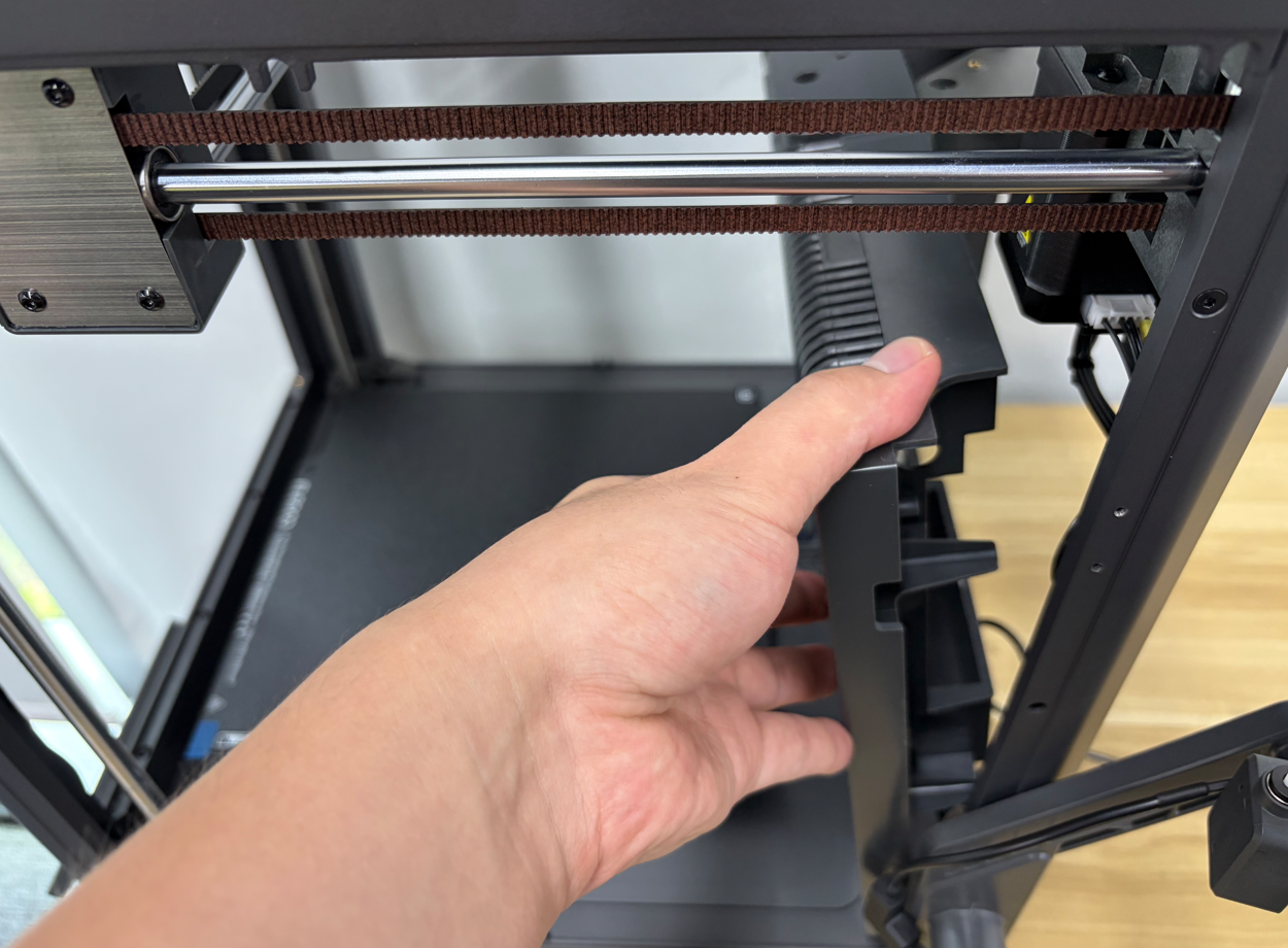
- Return the printer to its upright position.
- Remove the partition from the right-side cover.
¶ Remove the CAN Bus Connector
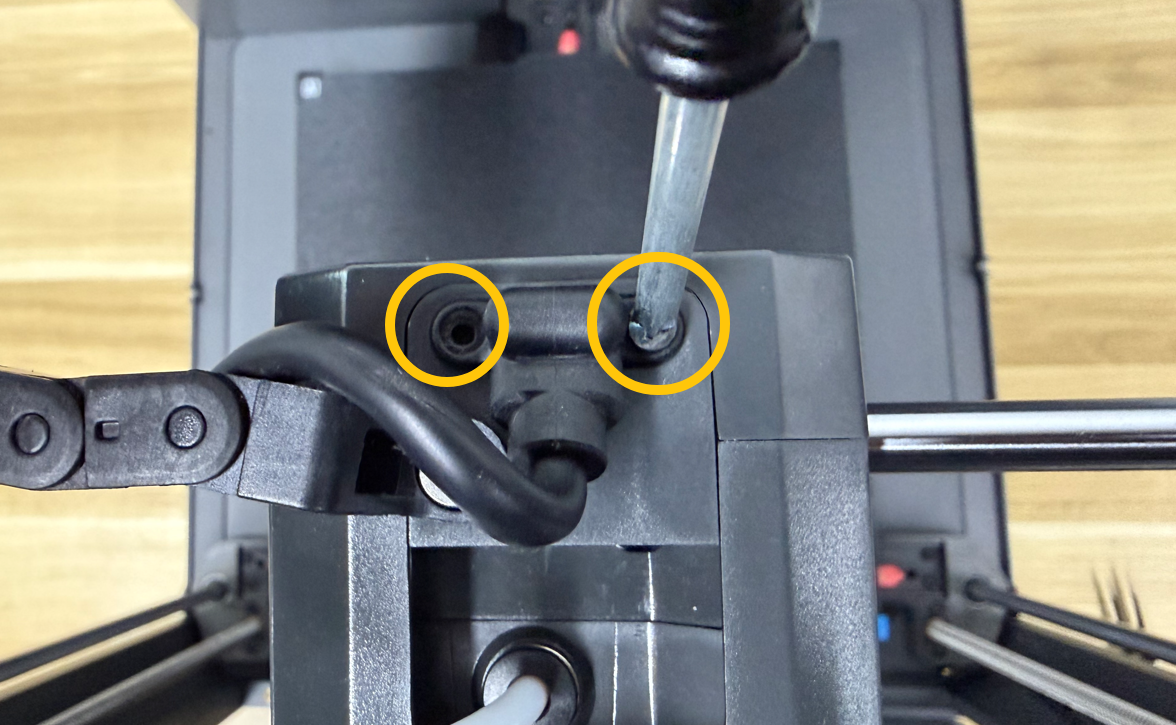
¶ Step 1. Remove the Connector
Using a Phillips screwdriver, remove the 2 screws securing the CAN Bus connector.
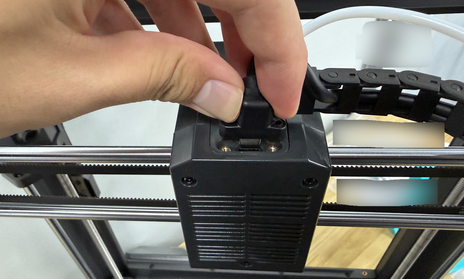
¶ Step 2. Disconnect the Connector
Disconnect the CAN Bus connector.
¶ Remove the Tank Chain
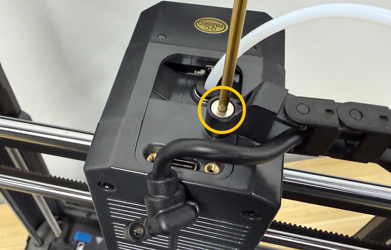
Using a 2.5 mm Allen key, remove the screws securing the tank chain, then remove the tank chain.
¶ Remove the PTFE Tube
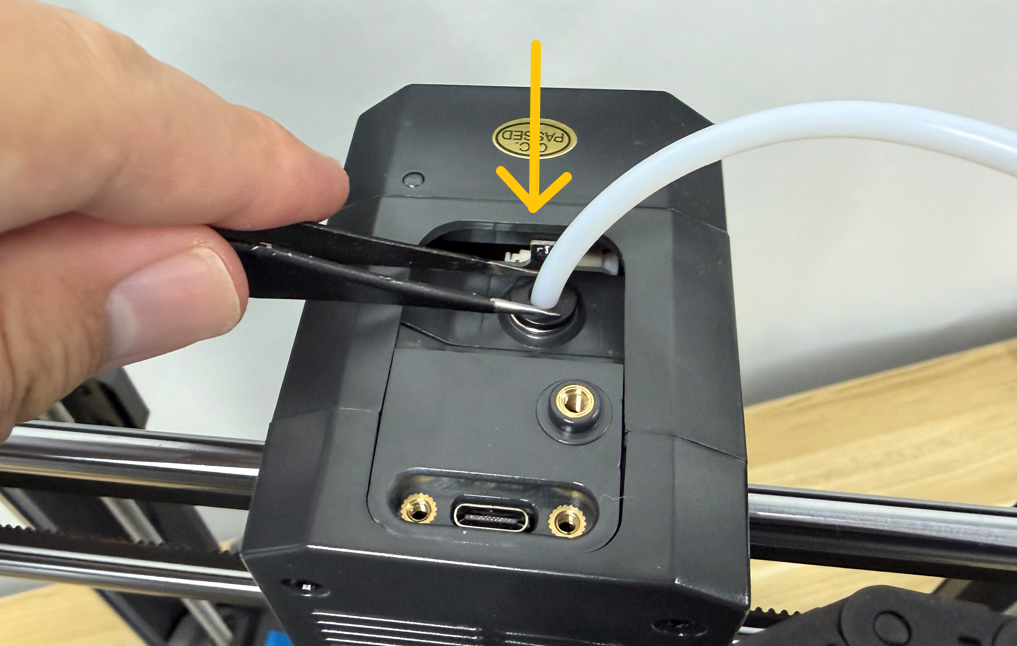
Using tweezers, press down the collet on the PTFE tube connector, then pull the PTFE tube upward to remove it.
¶ Remove the Upper Frame Housing
¶ Step 1. Remove the Upper Frame Housing Screws
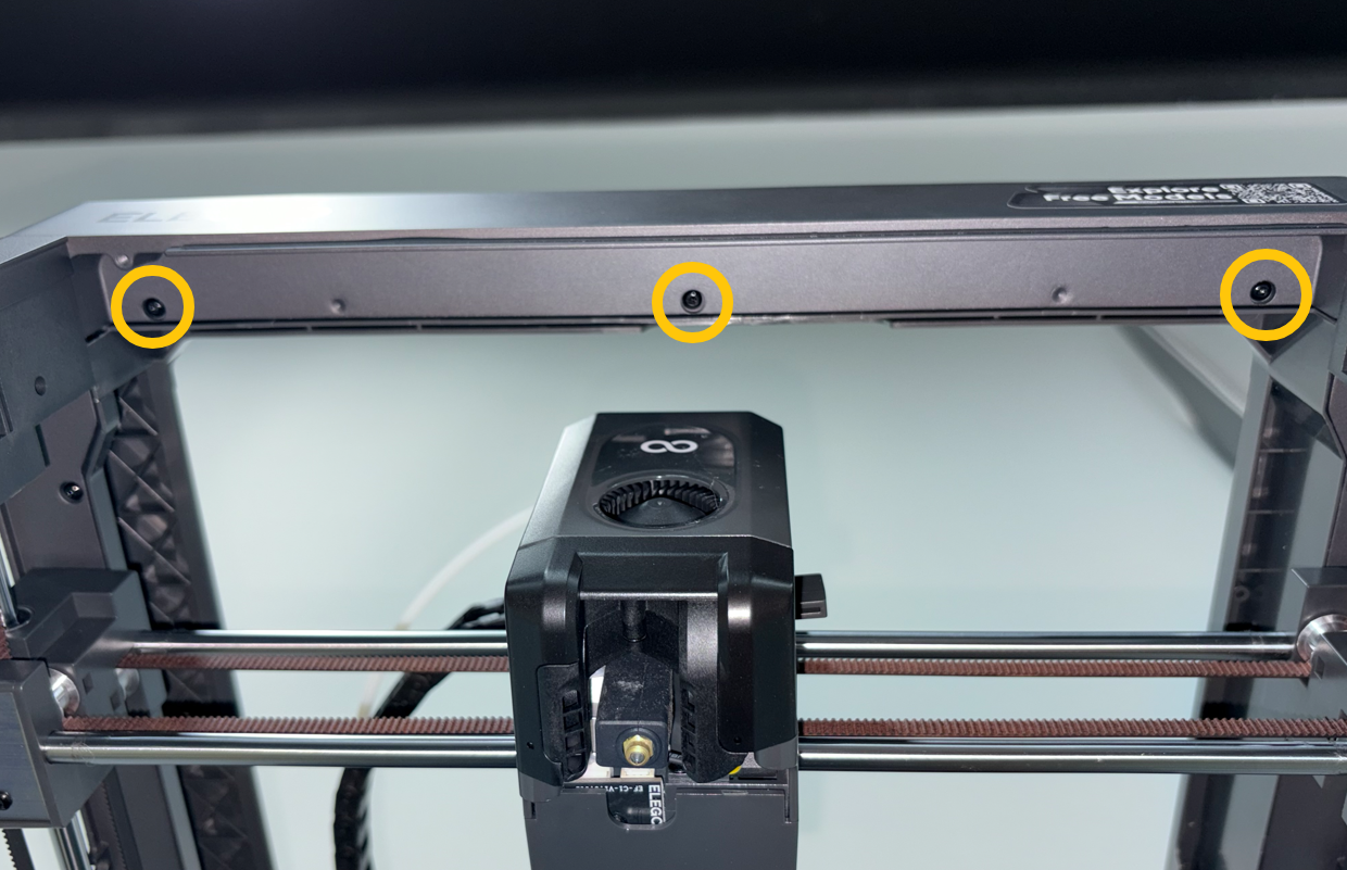
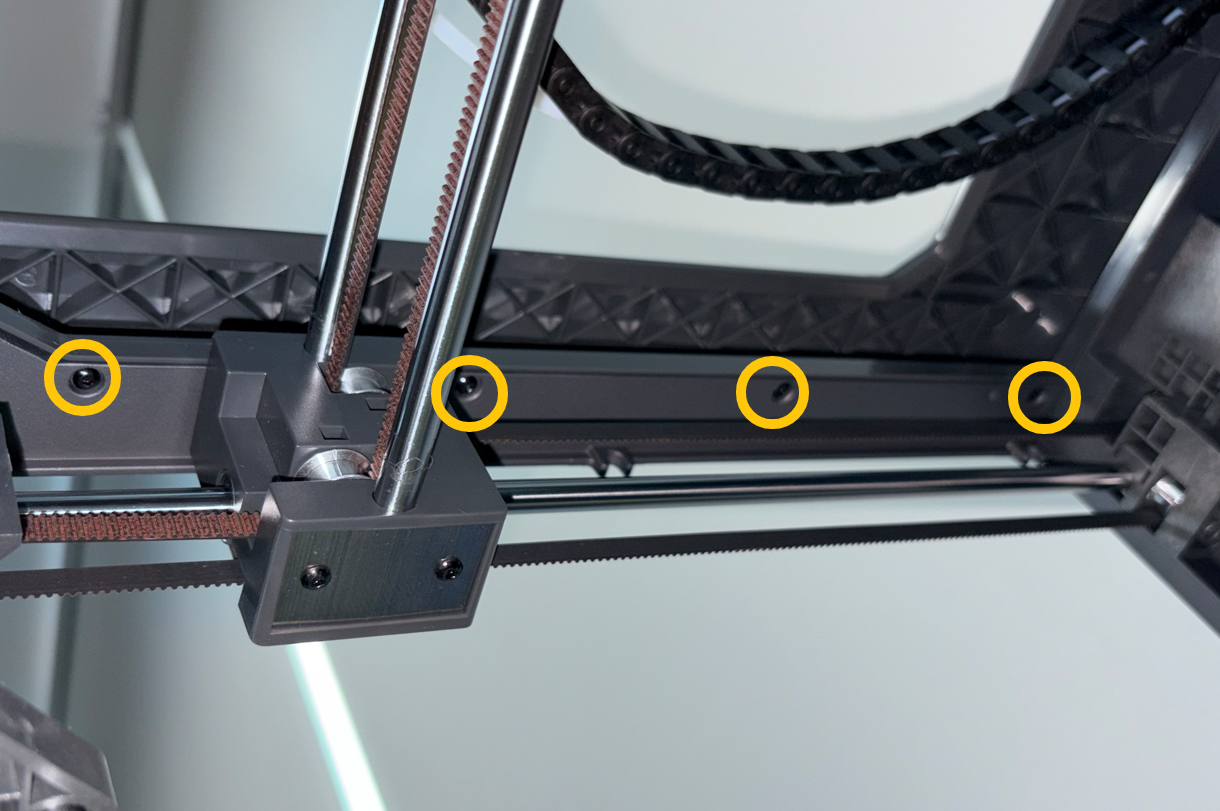
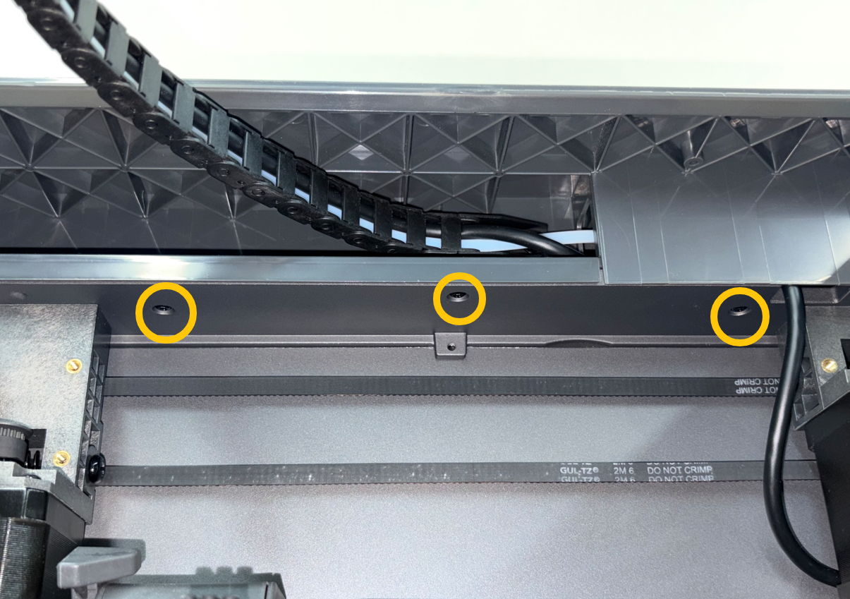
Using a 2.0 mm Allen key, remove the 13 screws securing the upper frame housing.
Front
Left
Rear
Right
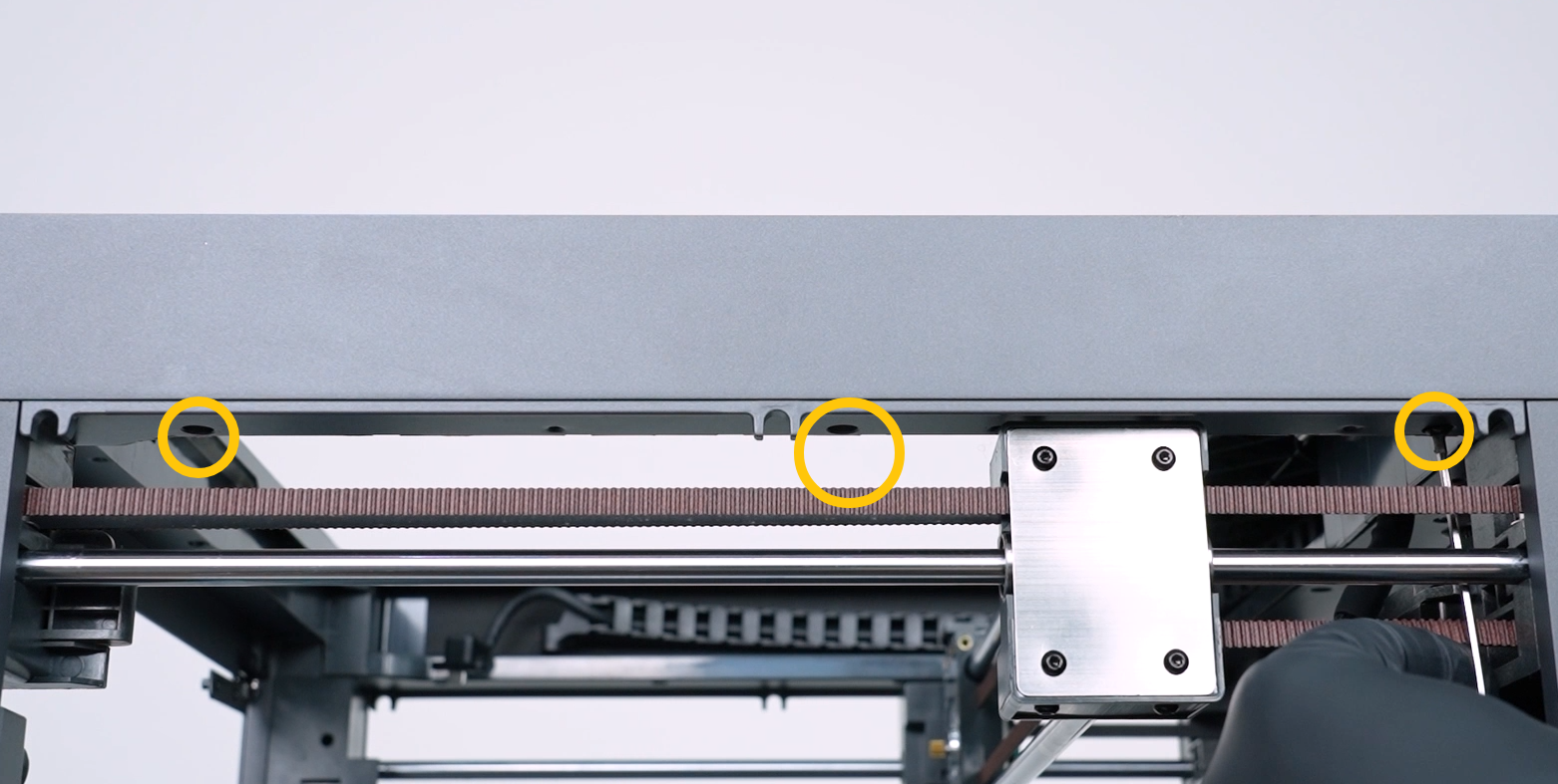
¶ Step 2. Lift the Upper Frame Housing
Lift the upper frame housing.
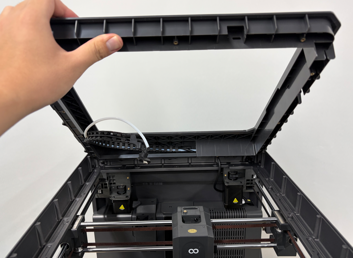
¶ Step 3. Remove the Tank Chain End Screws
Using a 2.0 mm Allen key, remove the 2 screws securing the end of the tank chain.
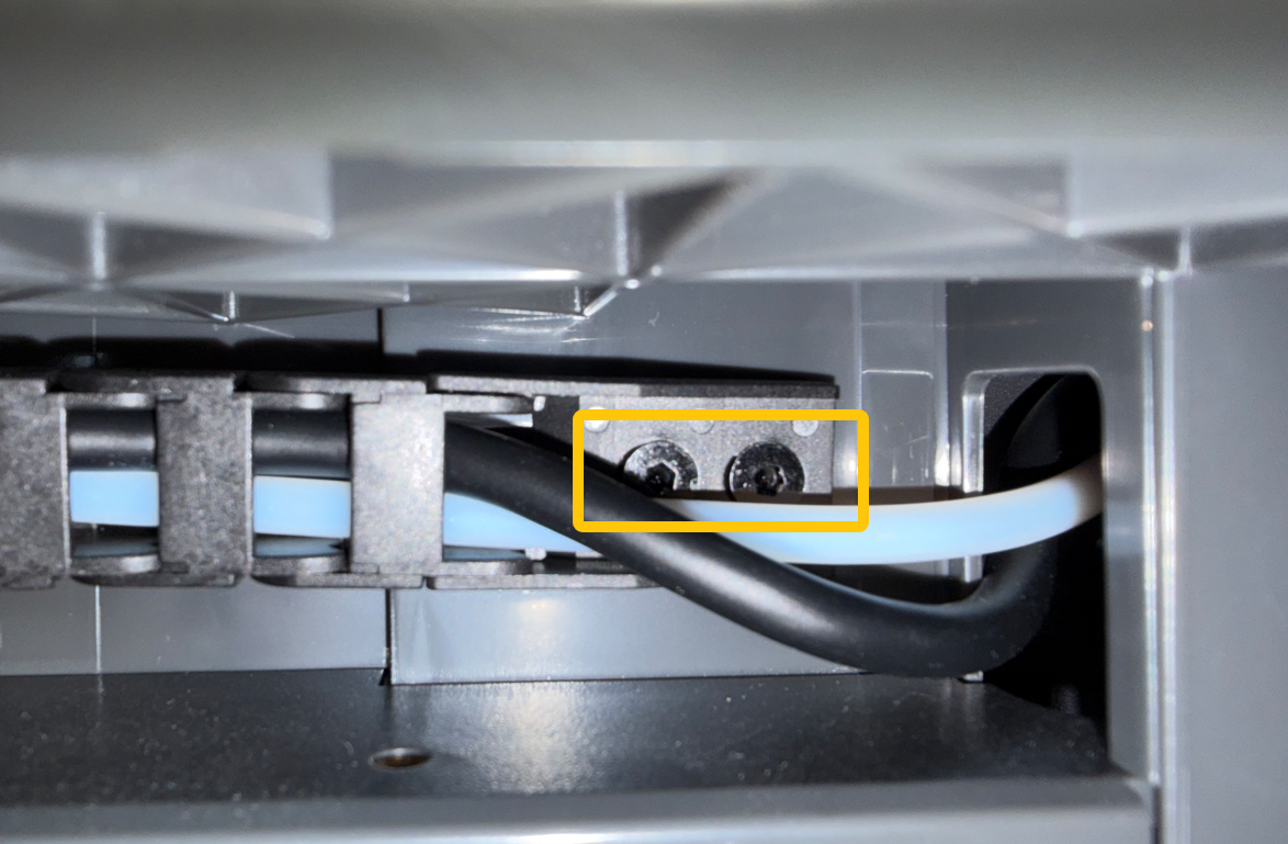
¶ Step 4. Remove the Upper Frame Housing
Remove the upper frame housing from the left side and place it on a workbench temporarily.
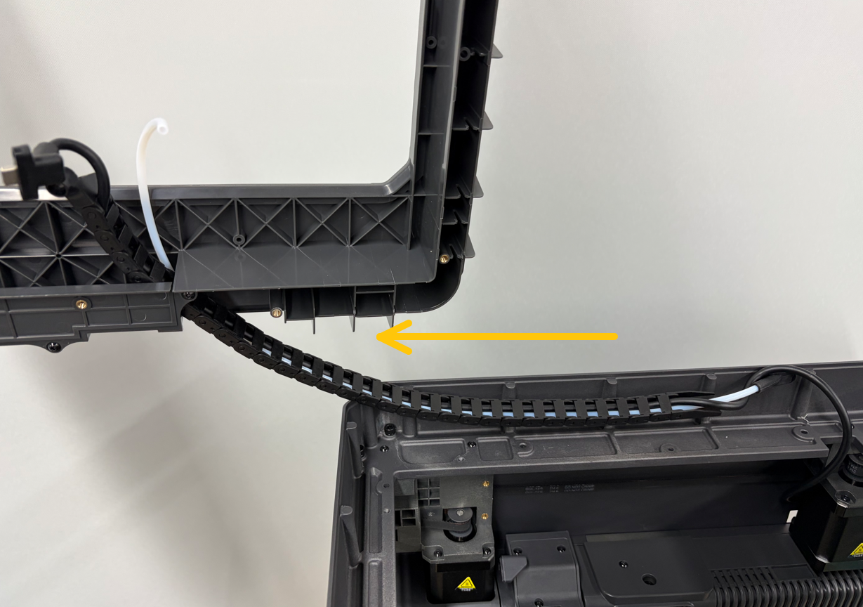
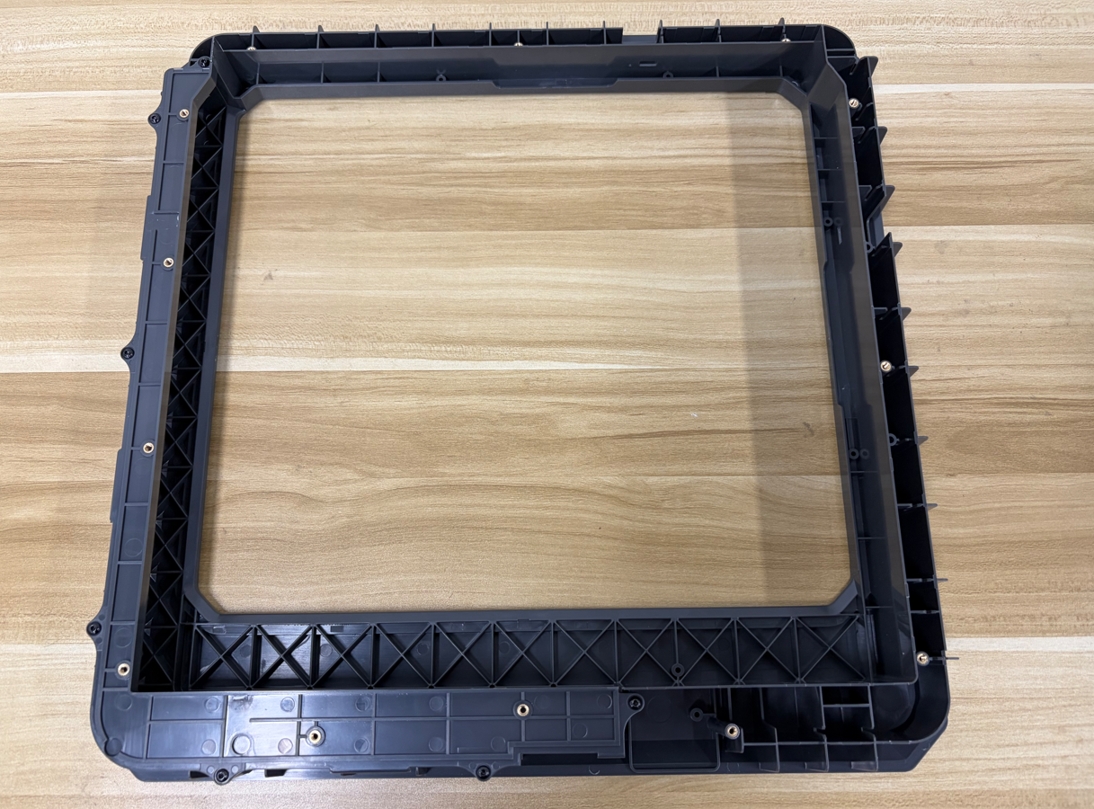
¶ Install the LED Strip
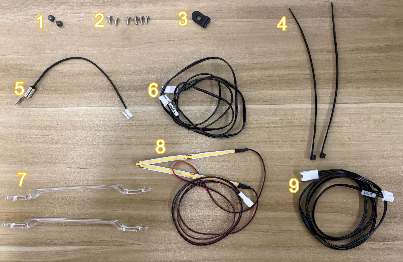
¶ Parts List
- Upper Frame Screw Hole Plugs ×2
- Self-tapping Screws (KB3×6) ×6
- R-type Cable Clamp ×1
- Cable Ties ×2
- Chamber Thermistor ×1
- Chamber Thermistor Extension Cable ×1
- Light Covers ×2
- LED Strip ×1
- LED Strip Extension Cable ×1
¶ Installation Procedure
¶ Install the LED Strip
Route the LED strip through the slot in the upper frame housing.
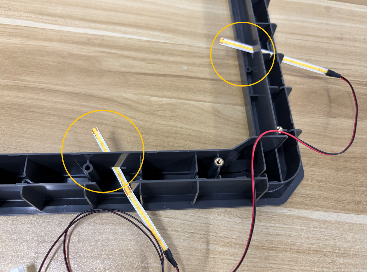
Place the LED strip cable into the cable channel of the upper frame housing.
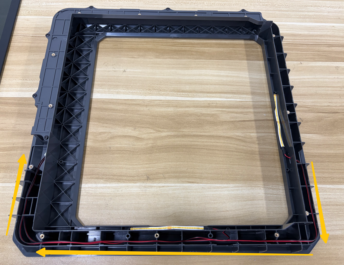
Remove the protective backing from the LED strip.
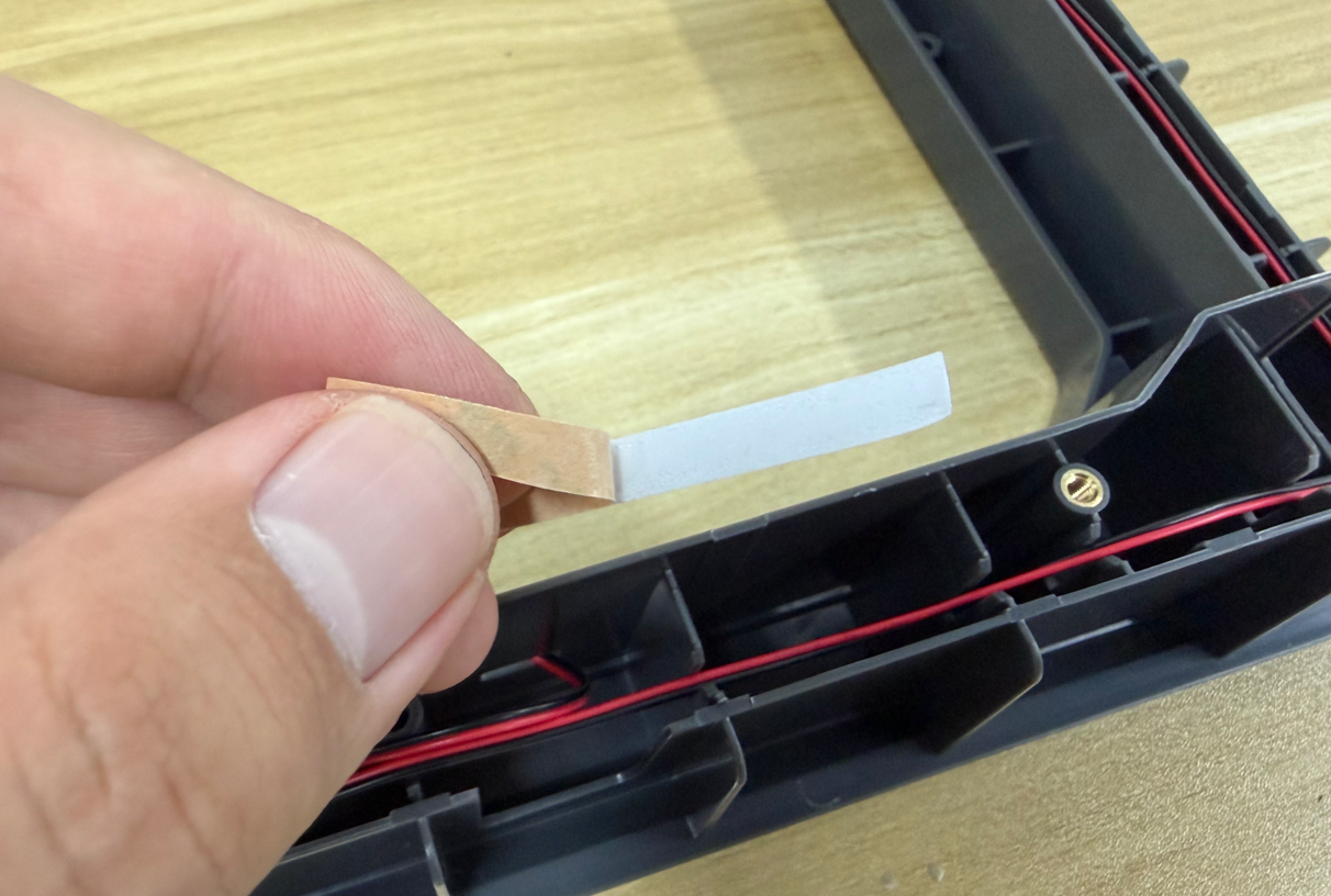
Attach the LED strip into the groove on the inside of the upper frame housing.
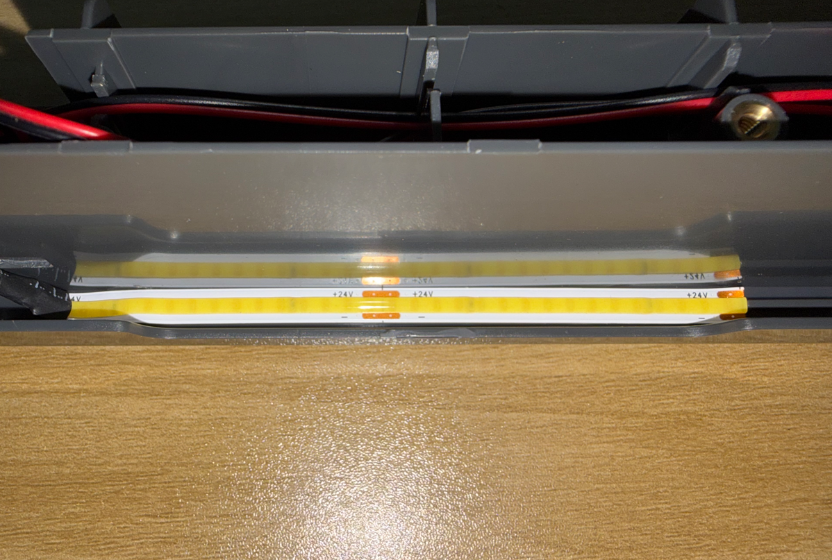
¶ Install the Light Cover
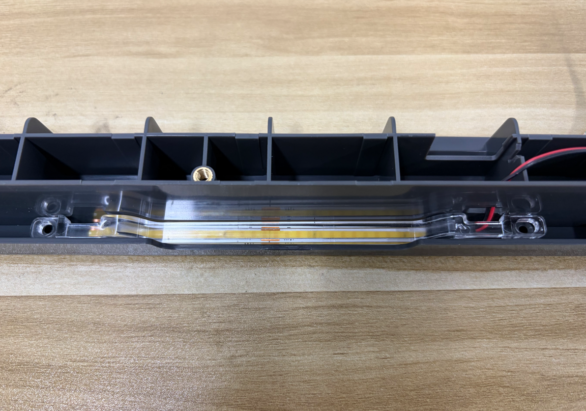
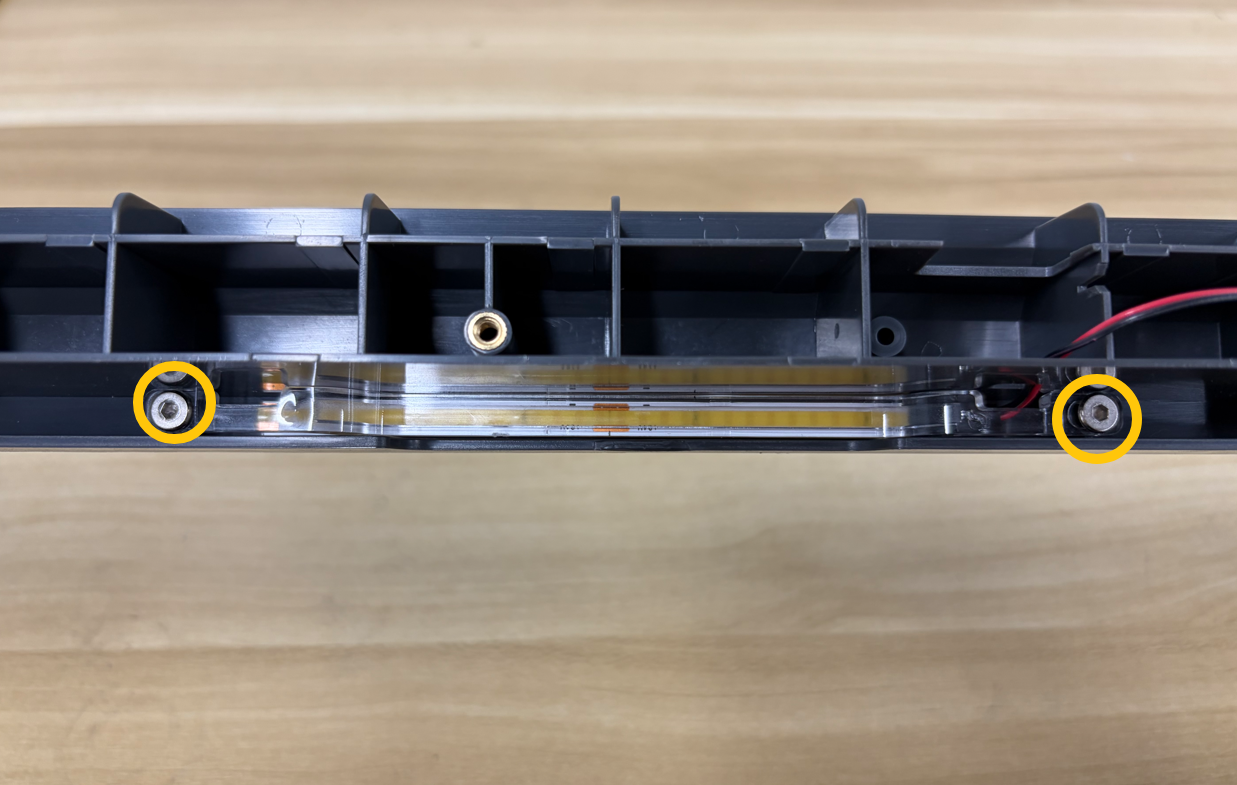
Position the light cover over the LED strip, then use a 2.0 mm Allen key to tighten the 2 screws securing the light cover.
¶ Install the Chamber Thermistor
Use a 2.0 mm Allen key to tighten the screw securing the chamber thermistor.
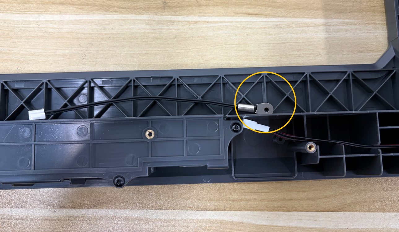
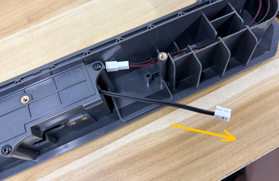
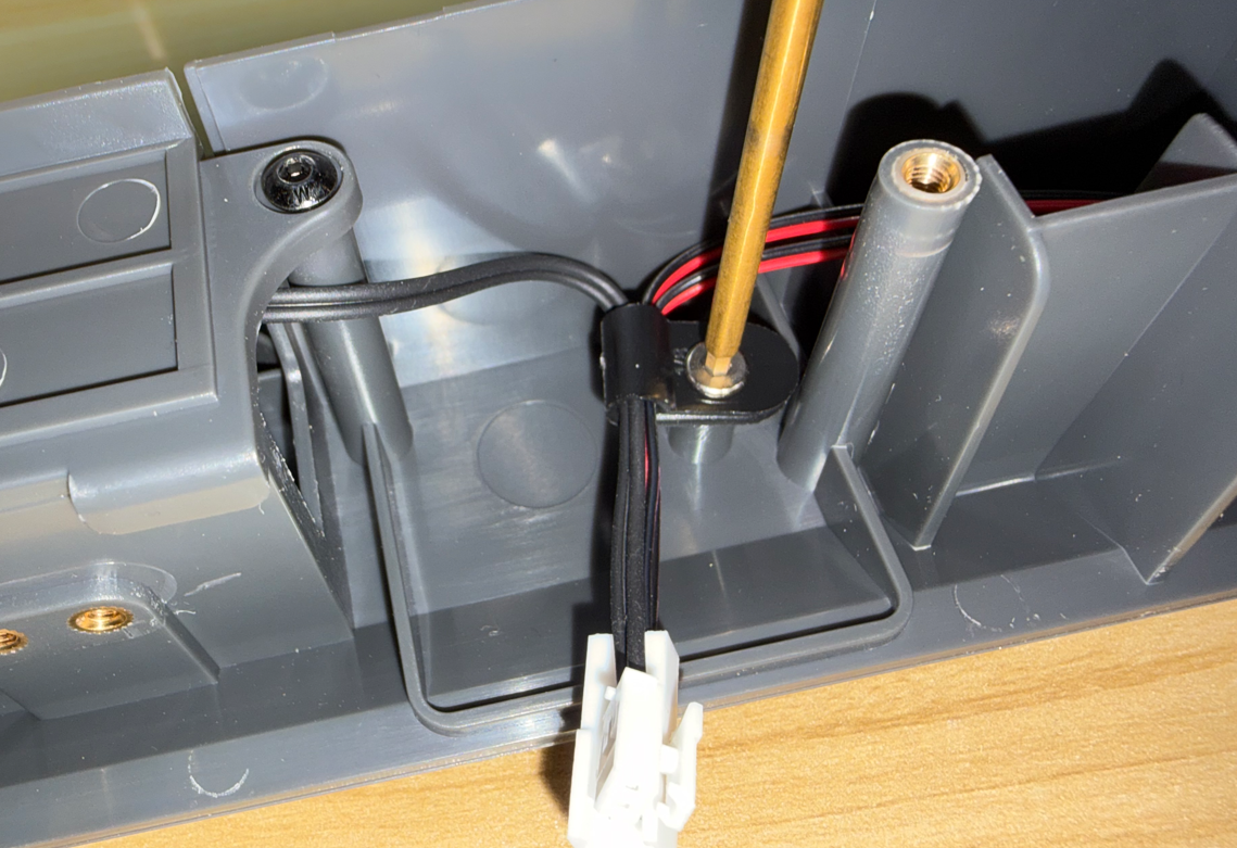
Route the chamber thermistor connector through the slot in the frame housing from the inside to the outside.
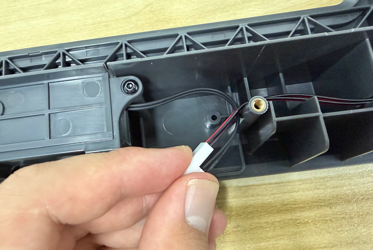
Hold the chamber thermistor connector and the LED strip connector together, then secure the cables using the cable clamp.
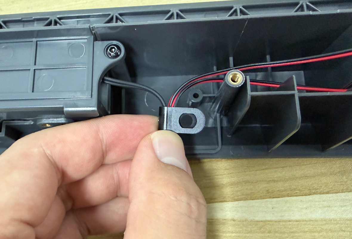
Use a 2.0 mm Allen key to tighten the screw securing the cable clamp.
¶ Connect the Extension Cables
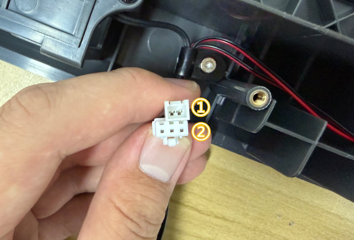
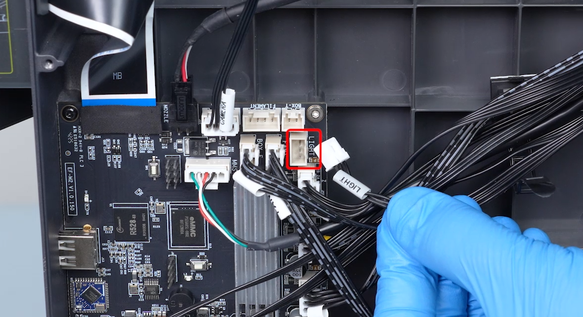
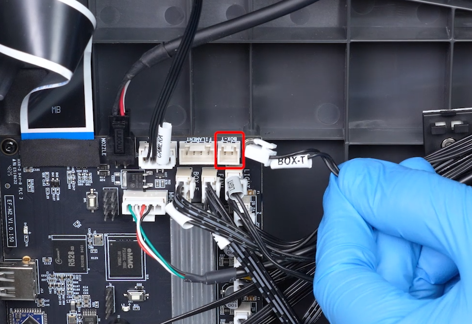
Connect the extension cables according to the connector labels.
- Connect connector ① to BOT-T.
- Connect connector ② to LIGHT.
¶ Install the Upper Frame Assembly
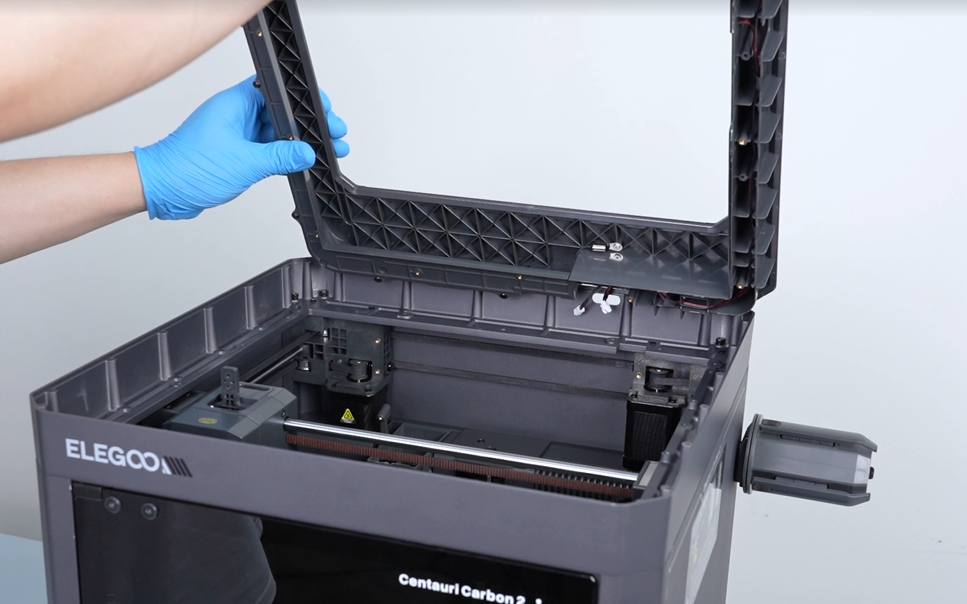
Place the assembled upper frame on top of the printer.
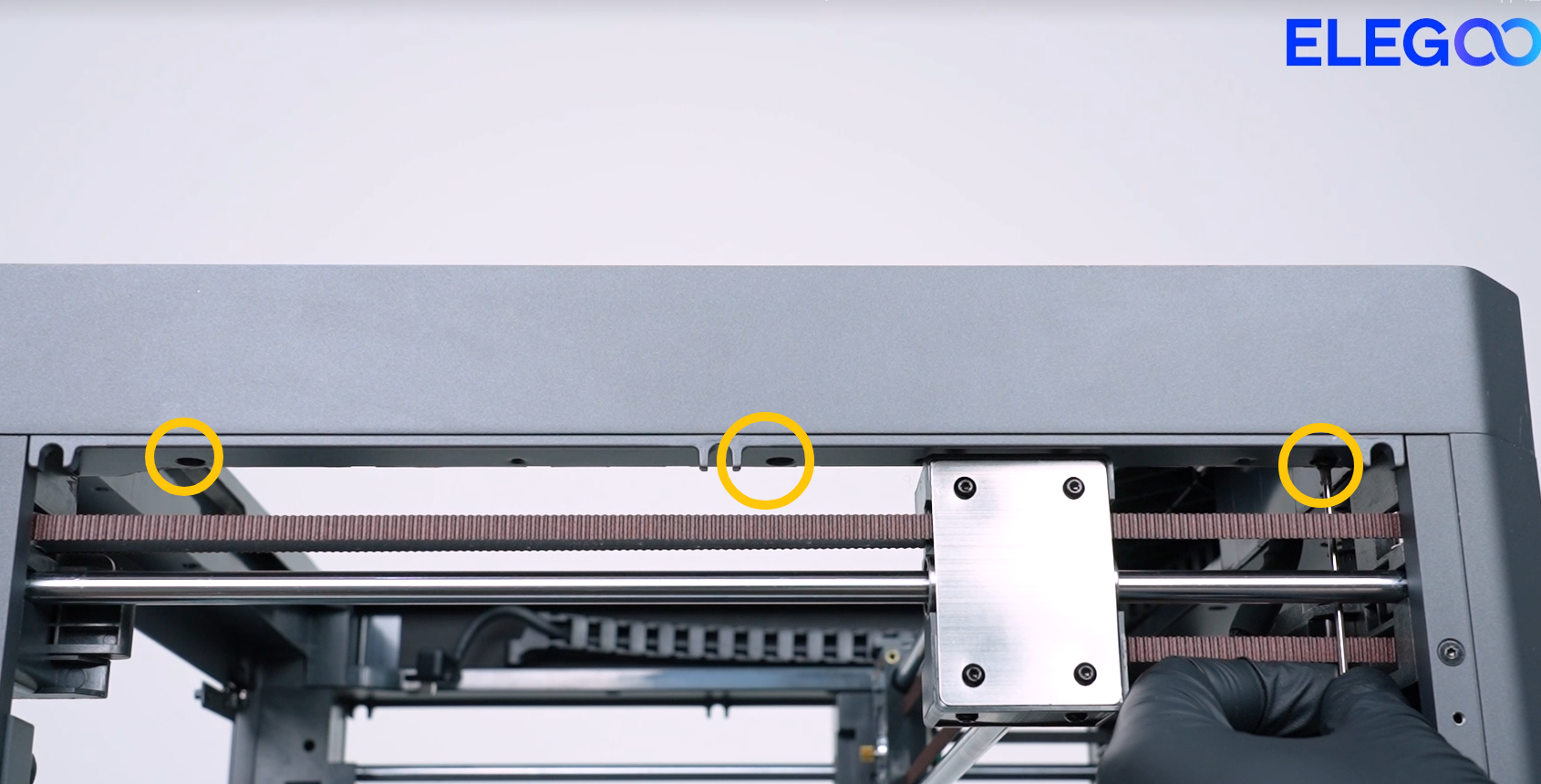
Use a 2.0 mm Allen key to tighten the 13 screws securing the upper frame assembly.
Front
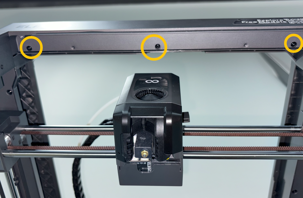
Left

Rear
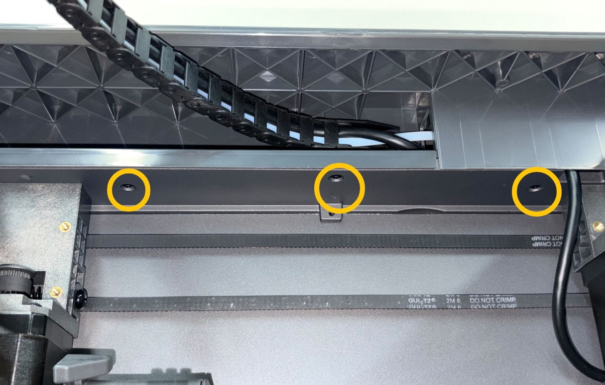
Right
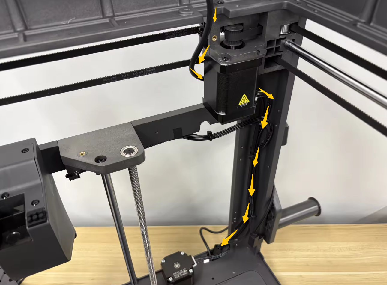
Route the cables in the direction indicated by the arrow.
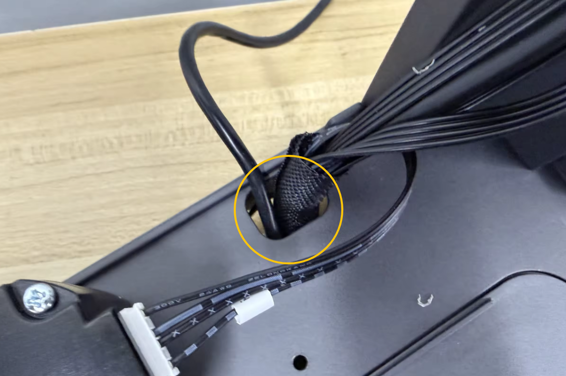
Feed the connectors through the slot on the top side of the printer base.
Connect the connectors to the corresponding ports on the mainboard according to the labels.
¶ Connect the PTFE Tube
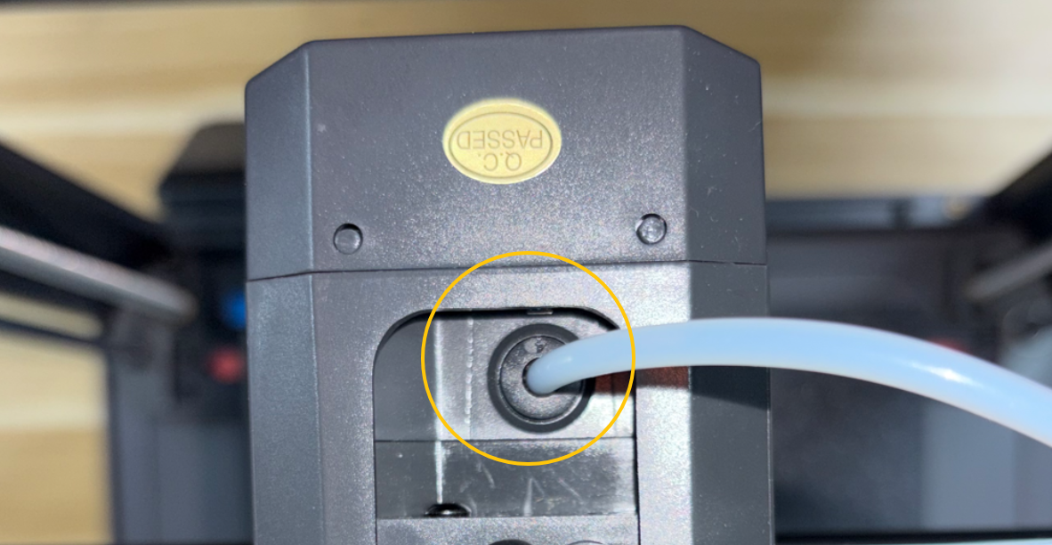
Insert the PTFE tube into the top of the tool head.
¶ Install the Tank Chain
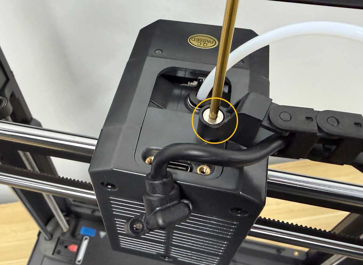
Position the tank chain in its original location, then use a 2.5 mm Allen key to tighten the mounting screws.
¶ Install the CAN Bus Connector
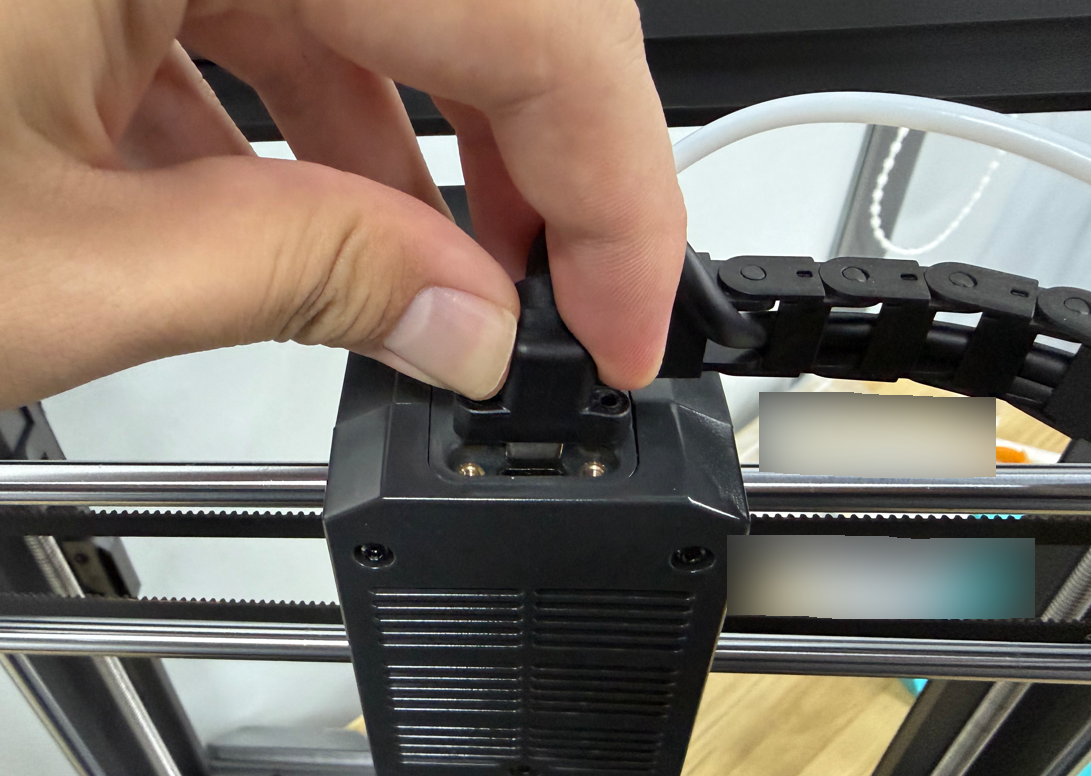
Insert the CAN Bus connector into its original position.
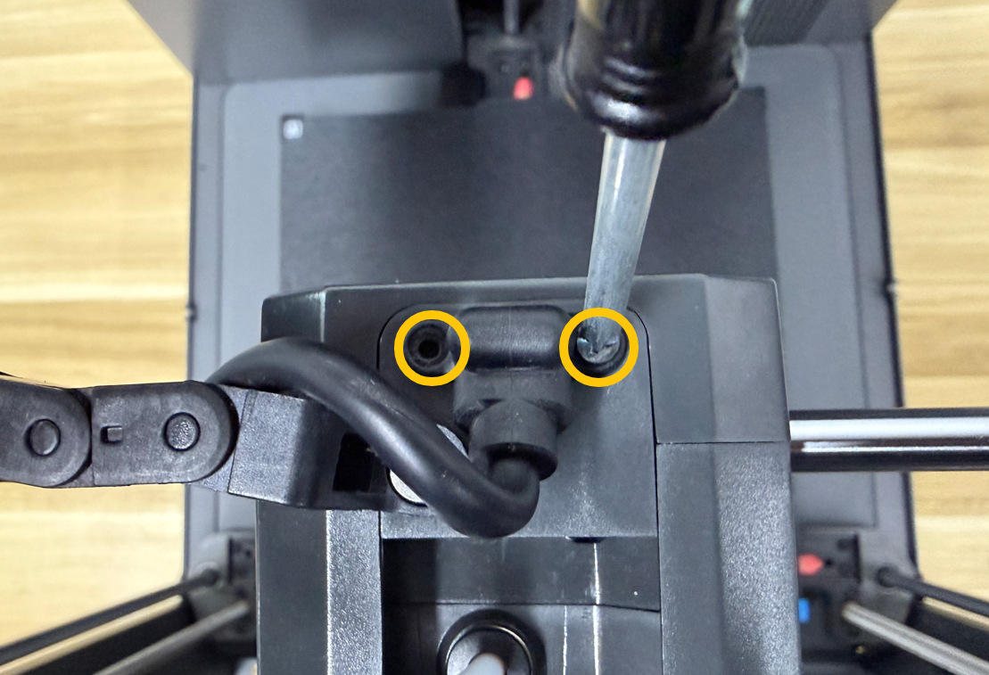
Use a Phillips screwdriver to tighten the 2 screws securing the CAN Bus connector.
¶ Install the Camera
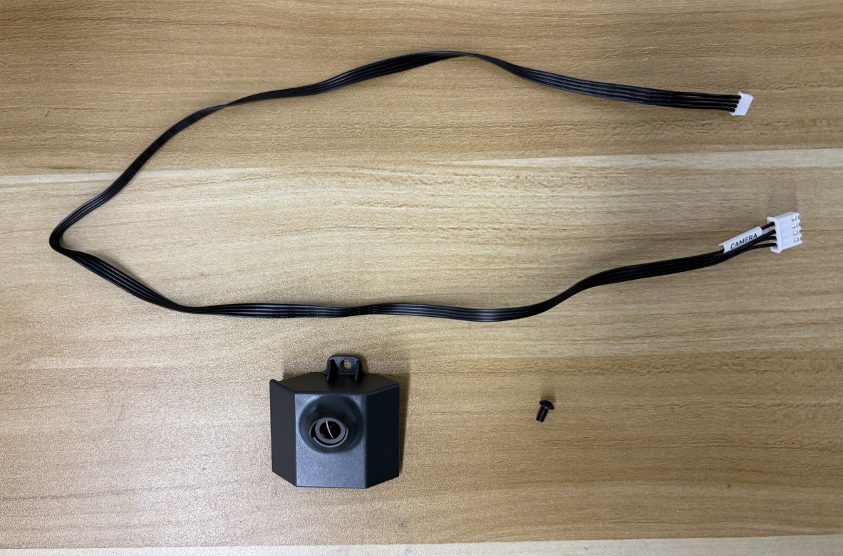
¶ Parts List
- Camera Cable ×1
- Camera ×1
- M3×6 Screw ×1
¶ Installation Procedure
¶ Remove the Foot Pad
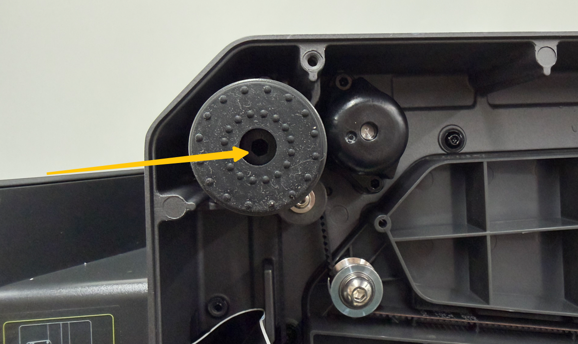
Use a 3.0 mm Allen key to remove the screw securing the foot pad (near the touch screen), then remove the foot pad.
¶ Connect the Camera Cable
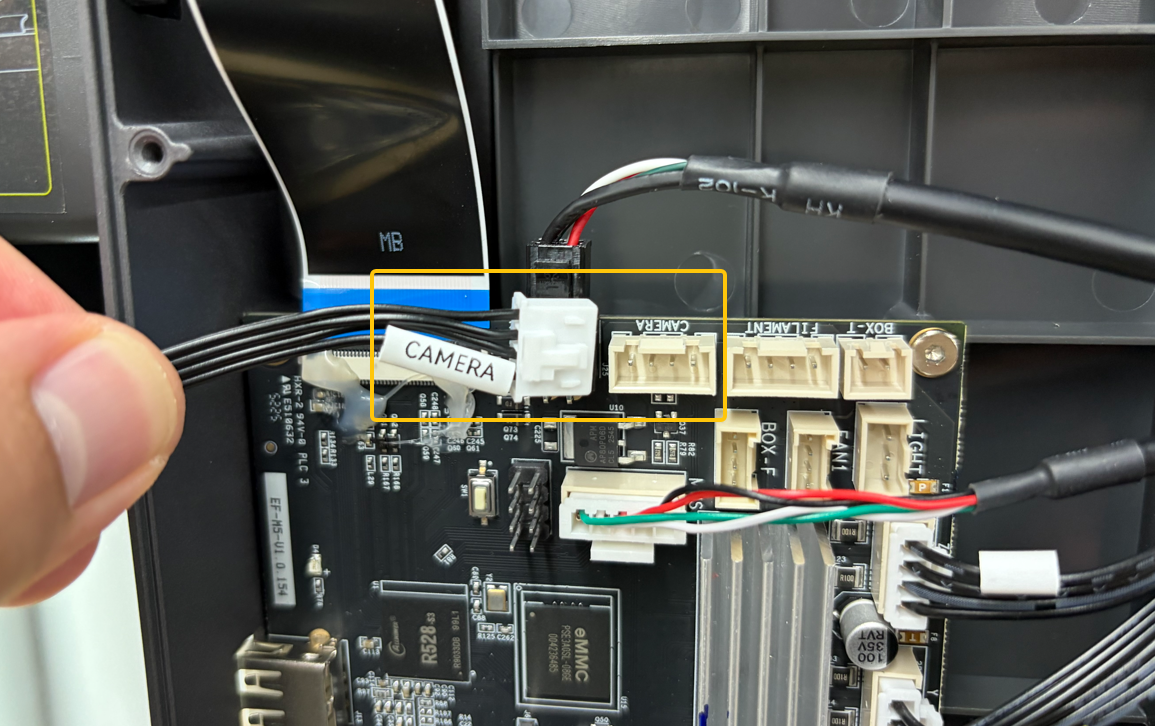
Connect the camera cable to the CAMERA port on the mainboard.
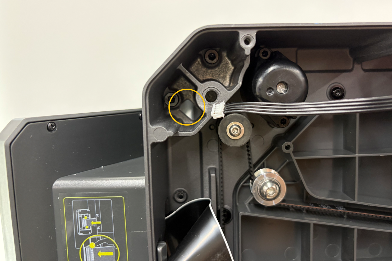
Route the camera connector through the cable slot.
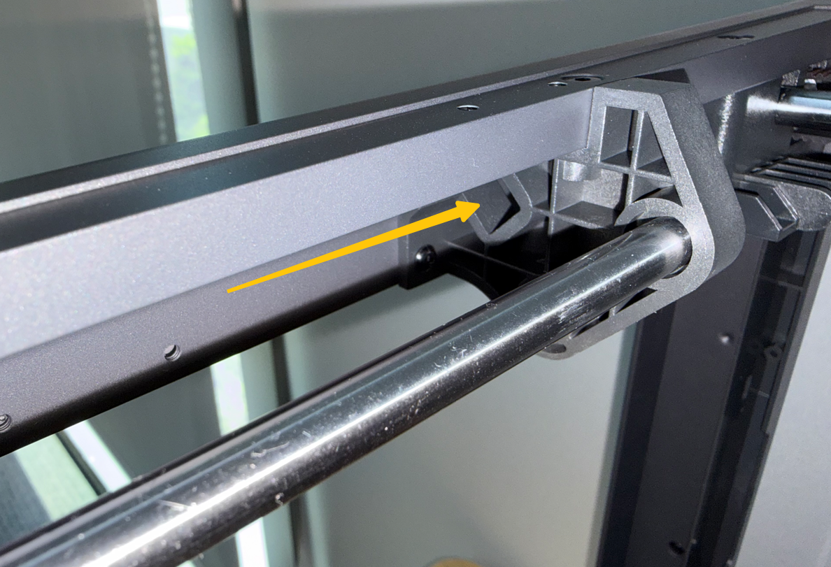
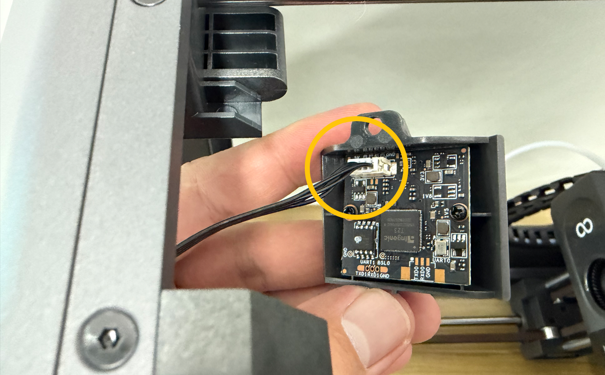
Connect the other end of the camera cable to the connector on the back of the camera.
¶ Install the Camera
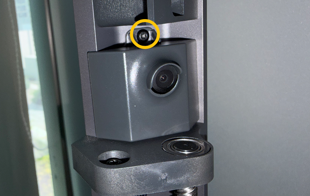
Position the camera in place, then use a 2.0 mm Allen key to tighten the mounting screw.
¶ Reinstall the Foot Pad
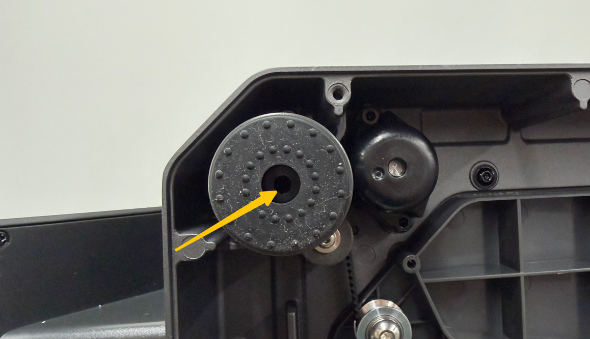
Reinstall the foot pad and tighten the mounting screw.
¶ Assemble the Divider Assembly
¶ Parts List
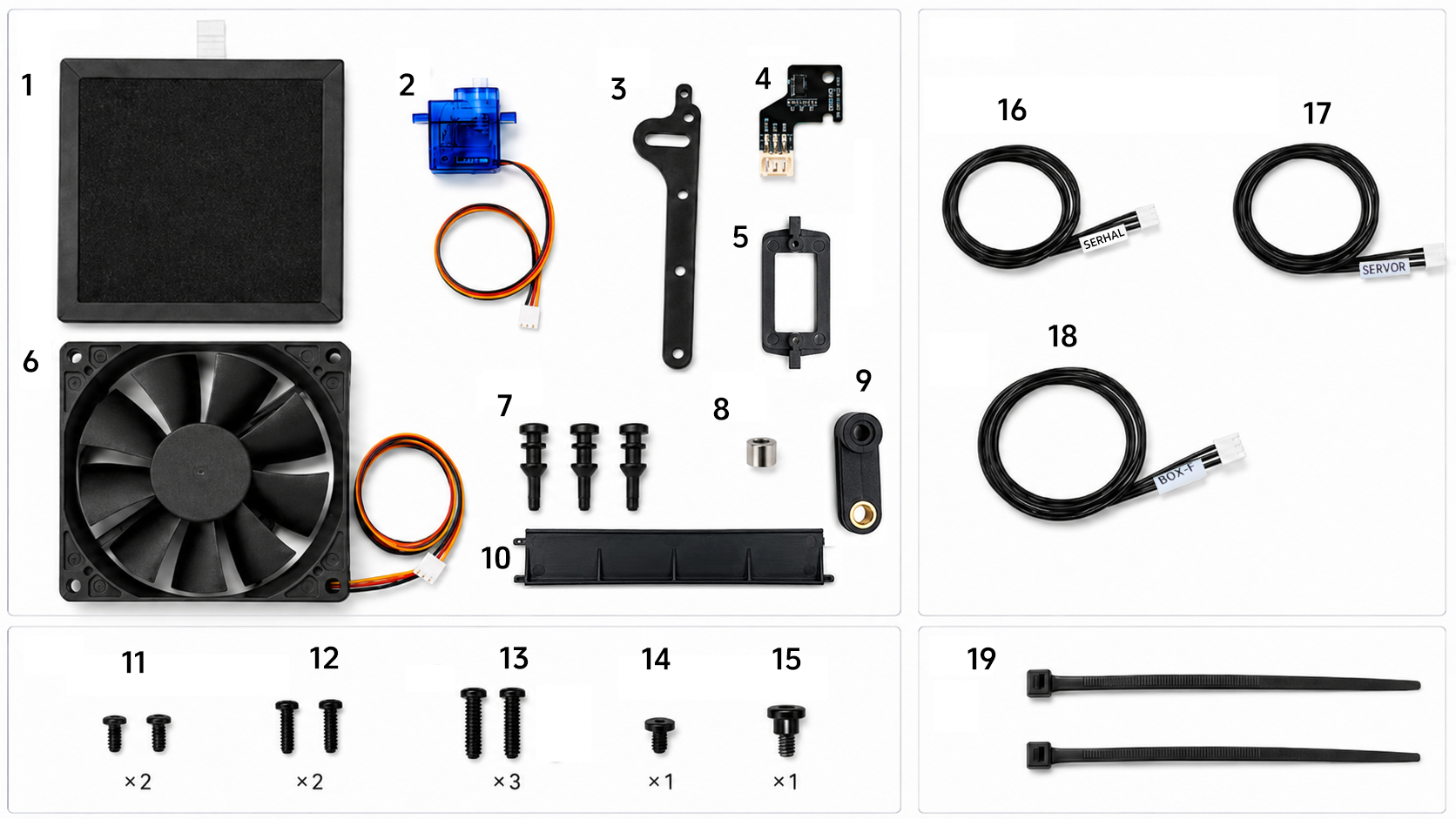
- Composite Filter ×1
- Servomotor ×1
- Air Damper Linkage ×1
- Servomotor Sensor Board ×1
- Servomotor Bracket ×1
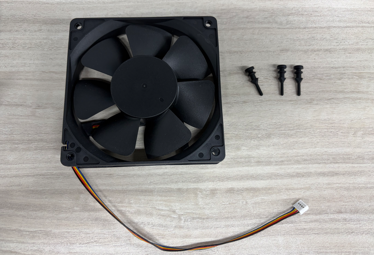
- Axial Fan ×1
- Fan Mounting Snaps ×3
- Cylindrical Magnet ×1
- Servo Arm ×1
- Air Dampers ×4
- PA2×6 Self-tapping Phillips Screws ×2
- PA2×8 Self-tapping Phillips Screws ×2
- PA3×10 Self-tapping Phillips Screws ×2
- PB2.3×5 Self-tapping Phillips Screw ×1
- Shoulder Screw (φ3.6 × 2.1 × M3) ×1
- Servomotor Extension Cable ×1
- Servomotor Sensor Board Cable ×1
- Fan Extension Cable ×1
- Cable Ties ×2
¶ Installation Procedure
¶ Install the Magnet
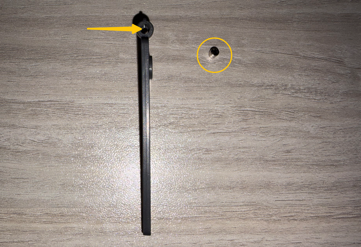
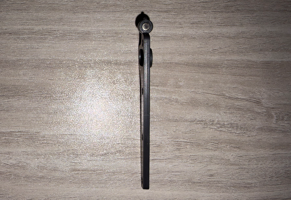
Insert the magnet into the recess of the servo arm and press it firmly into place.
¶ Install the Servo Arm
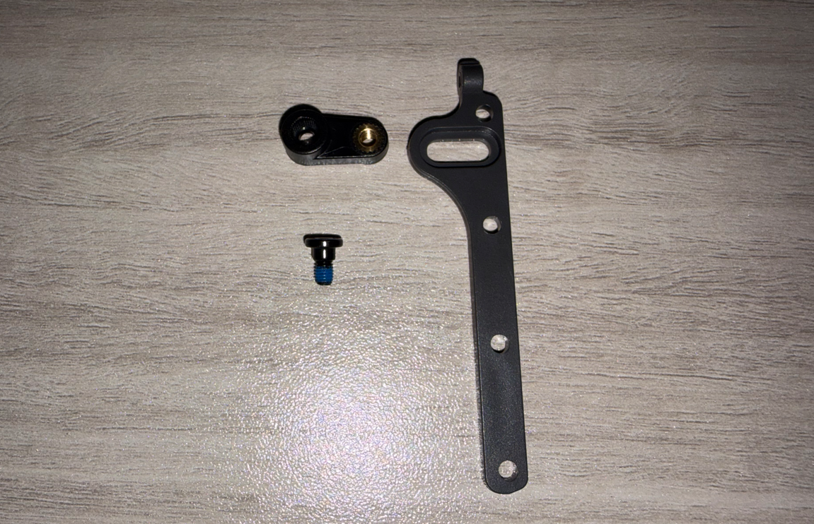
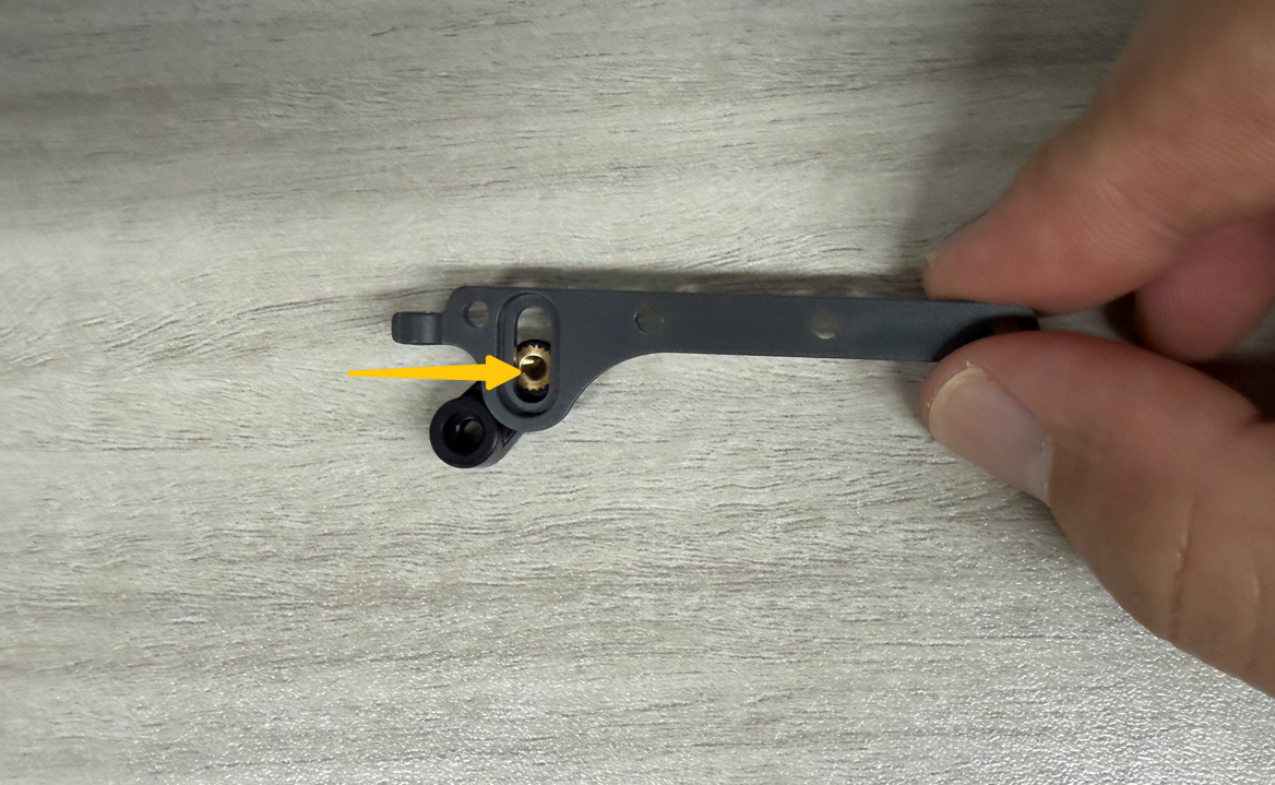
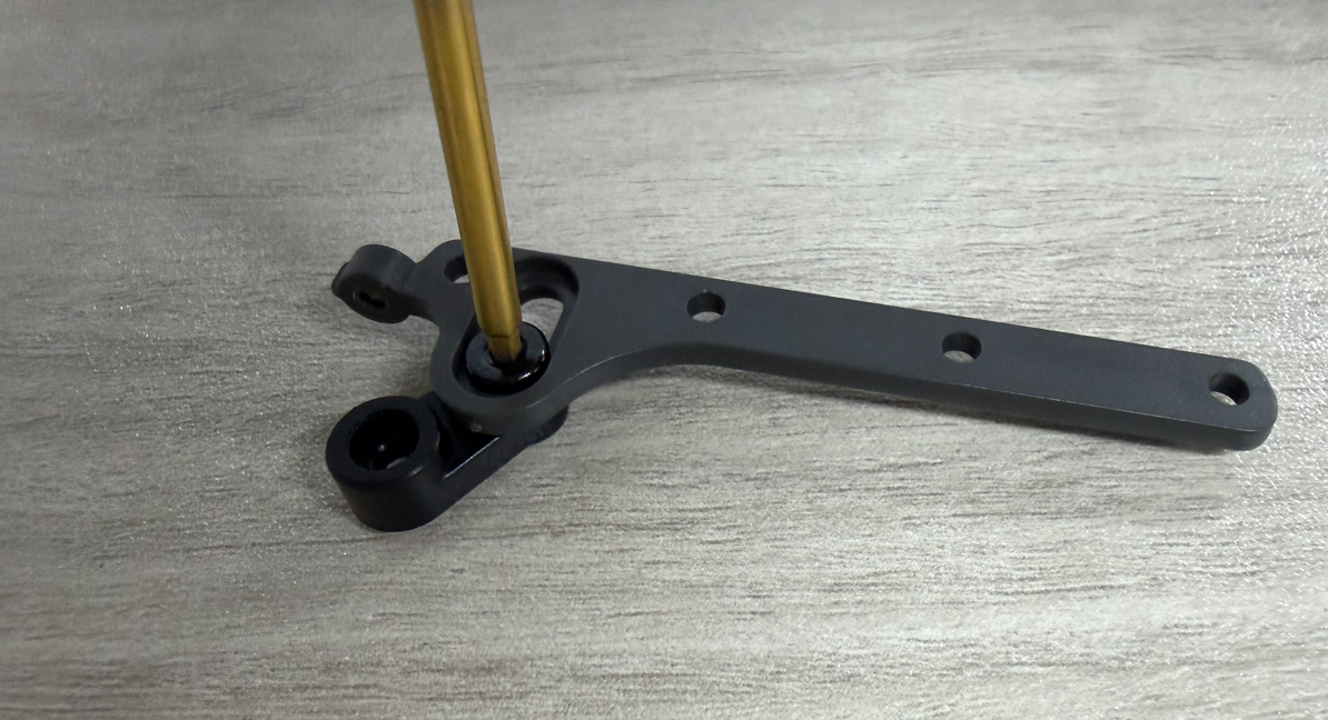
Position the air damper linkage on top of the servo arm.
Use a 2.0 mm Allen key to tighten the shoulder screw (φ3.6 × 2.1 × M3).
Note
Ensure the servo arm can move freely up and down after installation.
¶ Install the Servomotor Bracket
Position the servomotor bracket.
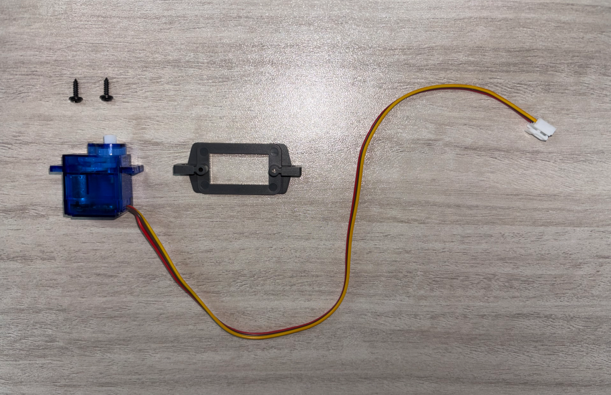
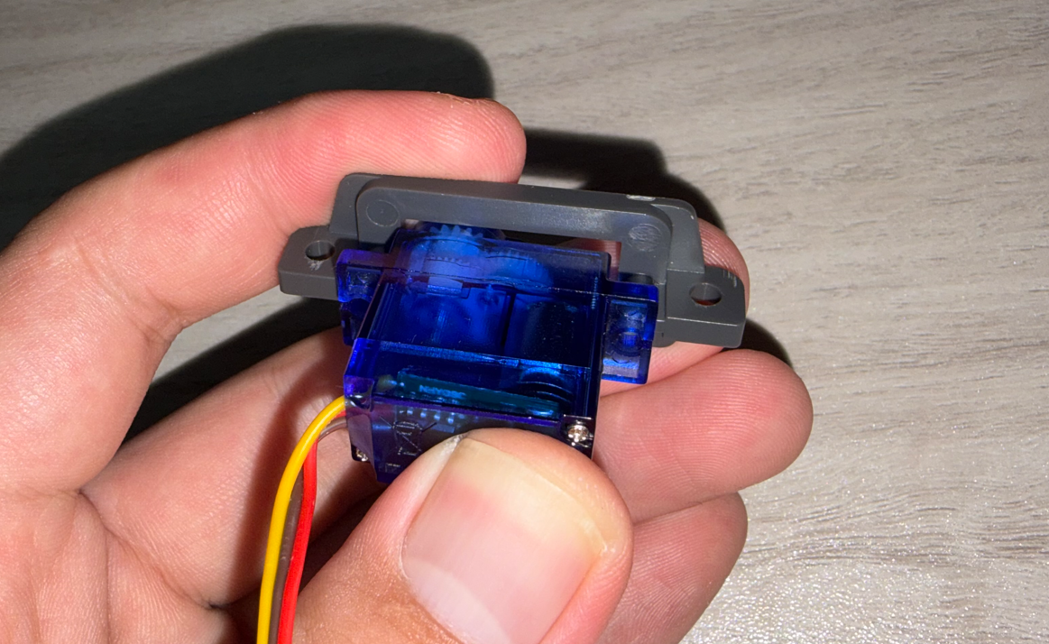
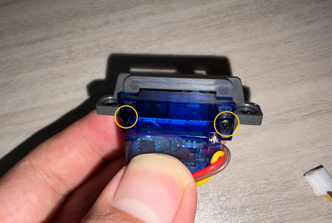
Place the servomotor onto the servomotor bracket and secure it using two PA2×8 self-tapping Phillips screws.
¶ Install the Servomotor Sensor Board
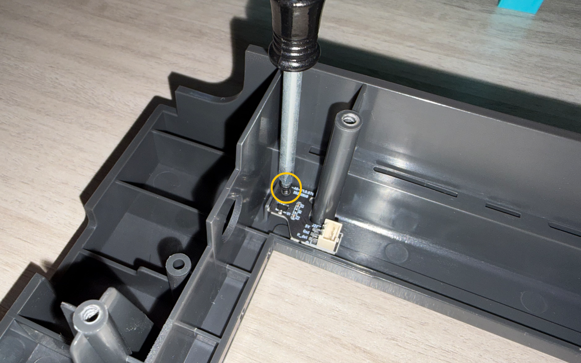
Position the servomotor sensor board on the back of the divider assembly.
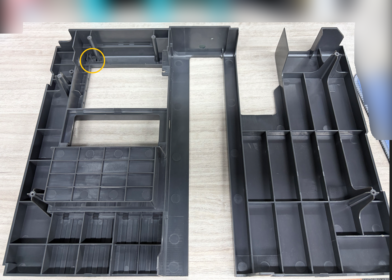
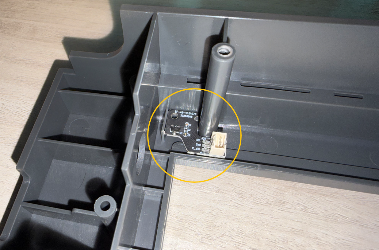
Use a Phillips screwdriver to tighten the PA2×6 self-tapping Phillips screws.
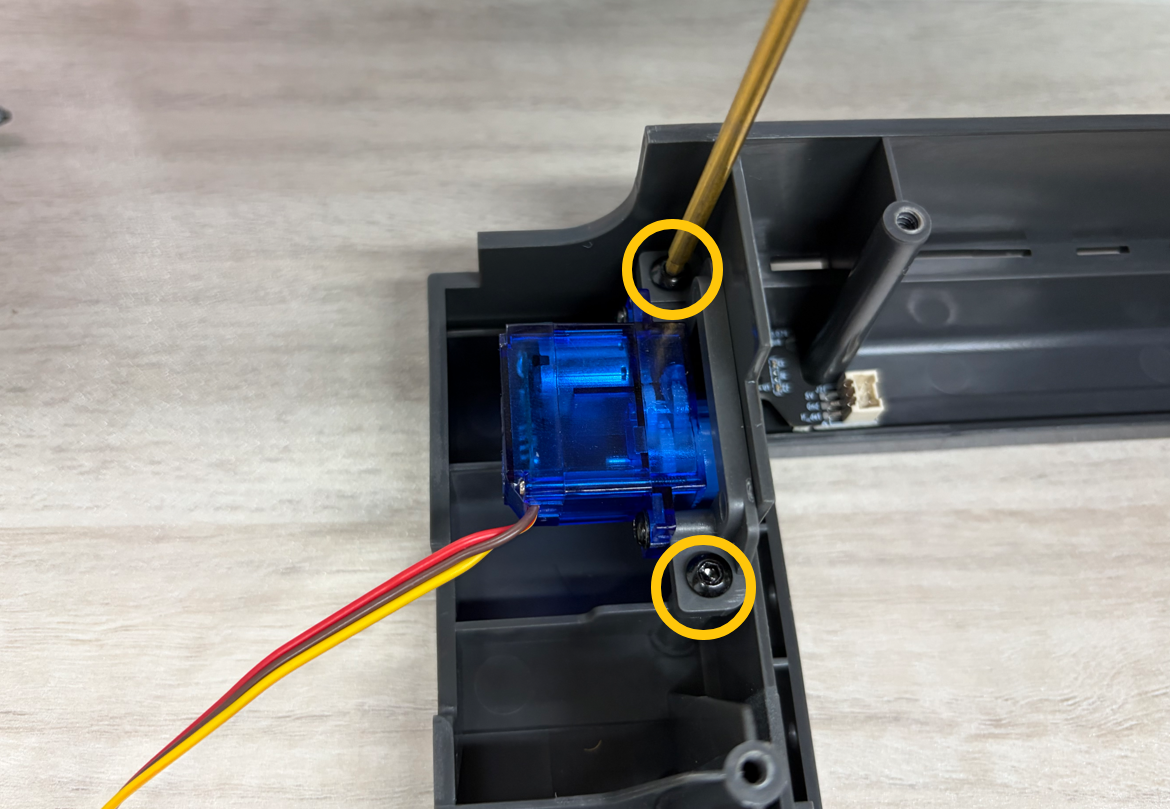
¶ Install the Servomotor
Place the servomotor into position and secure it using two PA3×10 self-tapping Phillips screws.
¶ Connect the Servo Arm to the Servomotor
Position the air damper linkage assembly with the servo arm installed.
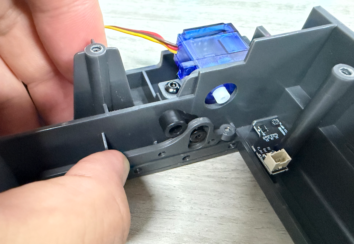
Align the servo arm with the servomotor output shaft, then press down until the servo arm snaps into place.
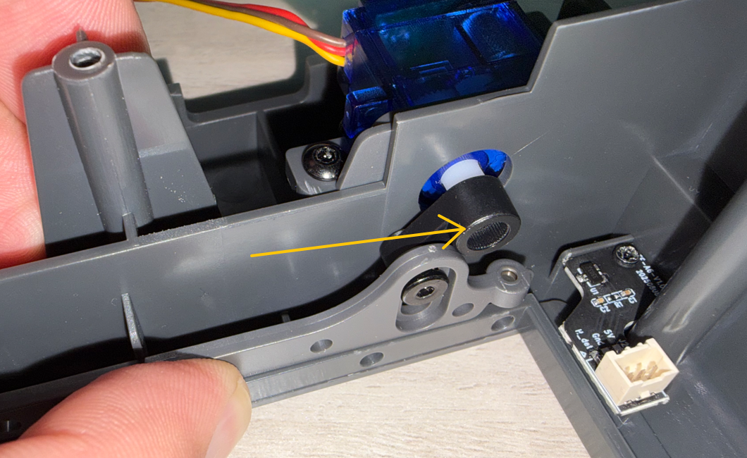
Tighten the PB2.3×5 self-tapping Phillips screw.
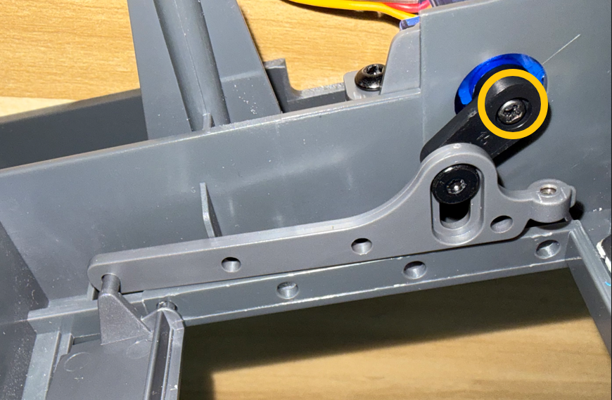
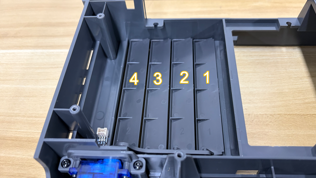
¶ Install the Air Dampers
Insert one end of the air damper into the servo arm and the lower slot.
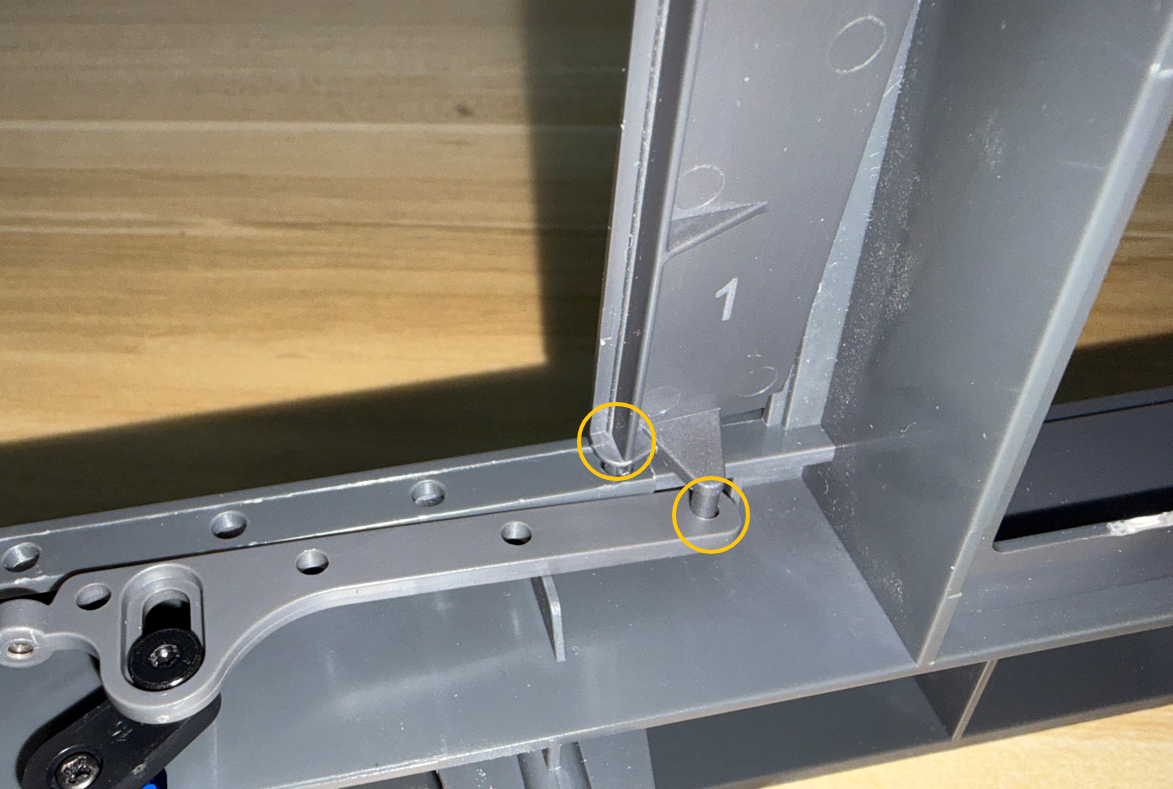
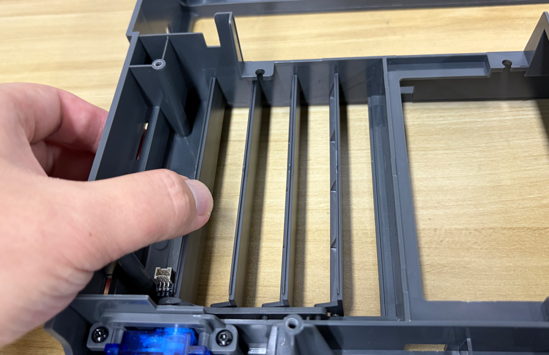
Gently press the center of the air damper to flex it slightly, then insert the opposite end into the upper slot.
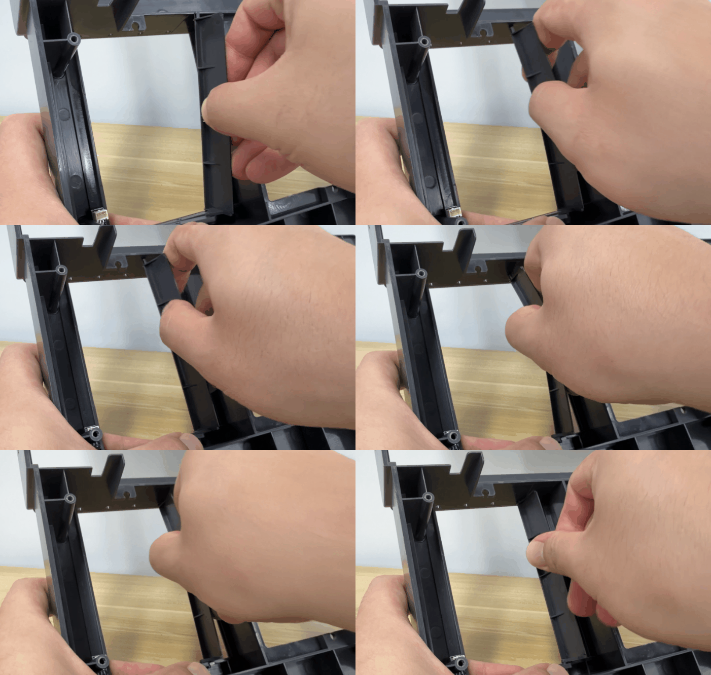
Repeat the same procedure to install the remaining three air dampers.
Note
After installation, manually move each air damper to ensure it can move freely without interference.
¶ Install the Case Fan
Position the Case Fan.
Insert the three fan mounting snaps into the mounting holes around the edge of the Case Fan.
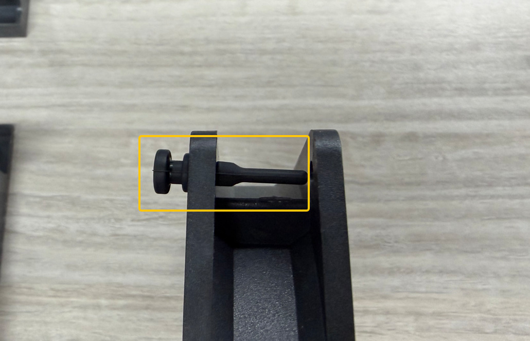
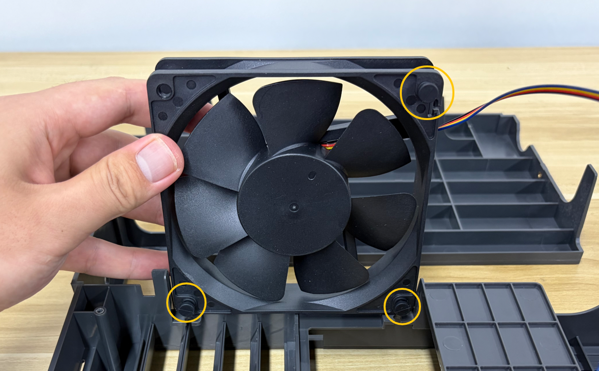
Note
Ensure all fan mounting snaps are fully seated and securely installed.
Pay attention to the orientation of the fan cable.
Align the assembled Case Fan with the slots in the divider assembly, then press the fan mounting snaps into the slots.
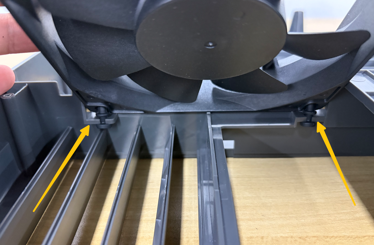
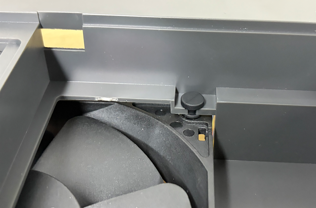
Turn the divider assembly over and secure the final fan mounting snap.
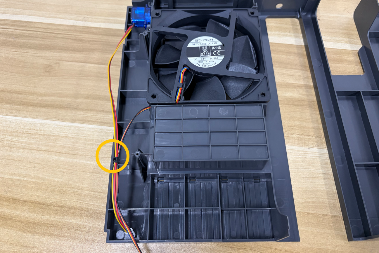
Use cable ties to secure the Case Fan cable and the servomotor cable.
¶ Install the Filter and Grille
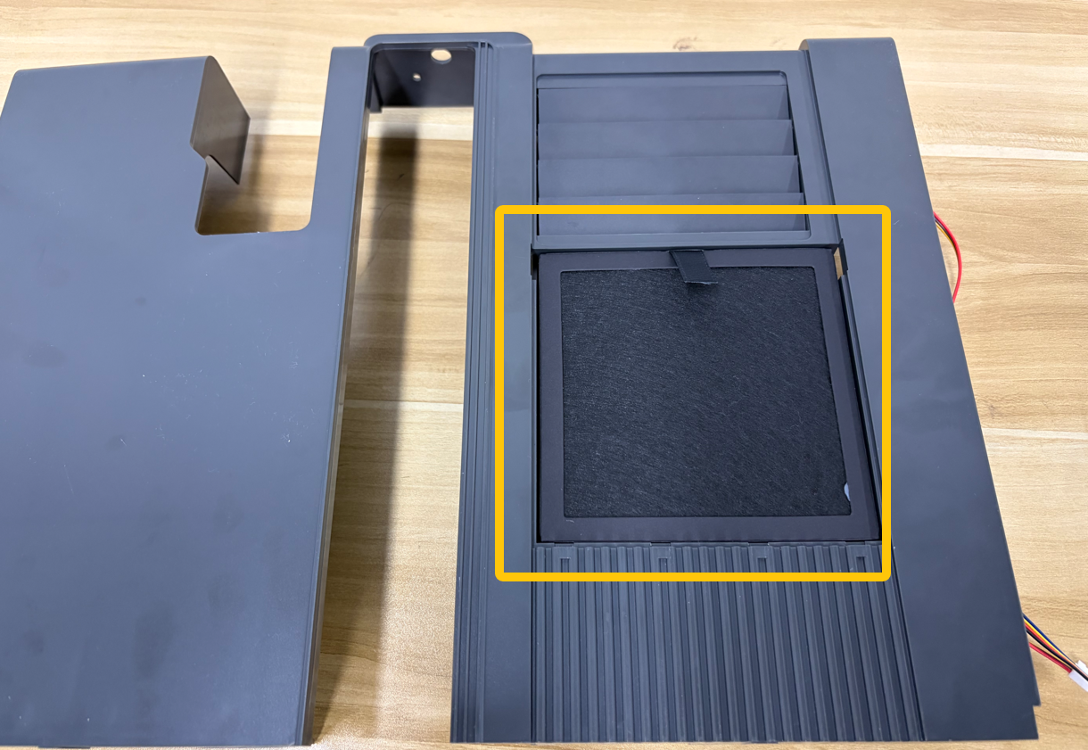
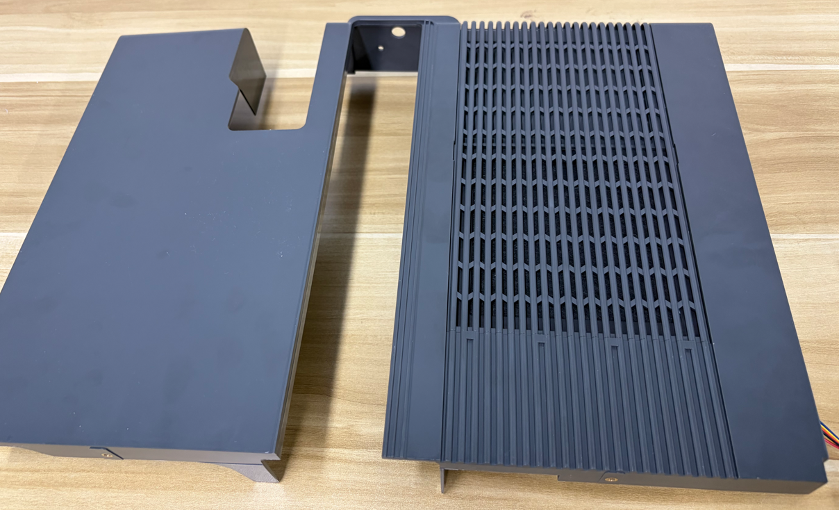
Place the composite filter into the slot of the divider assembly, then reinstall the grille.
¶ Install the Divider Assembly
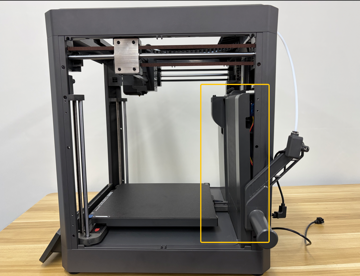
Place the assembled divider assembly into position.
Note
Do not install the mounting screws yet. Leaving the assembly unsecured at this stage allows easier cable routing, adjustment of the left and right enclosure panels, and cable management during the following installation steps.
¶ Install the Enclosure Panel Assembly
¶ Parts List
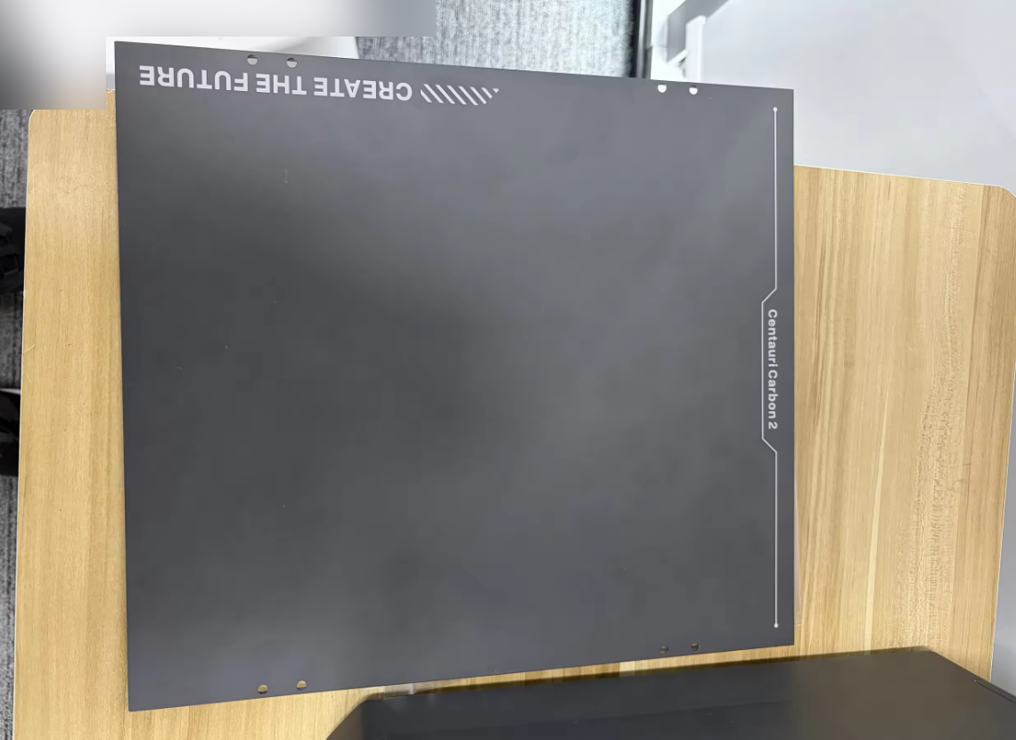
- Left Enclosure Panel Assembly ×1
- Right Enclosure Panel Assembly ×1
- Fan Extension Cable ×1
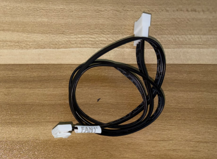
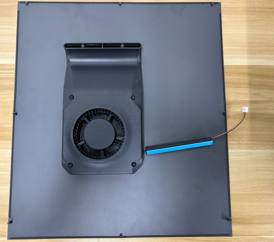
¶ Installation Procedure
¶ Install the Left Enclosure Panel
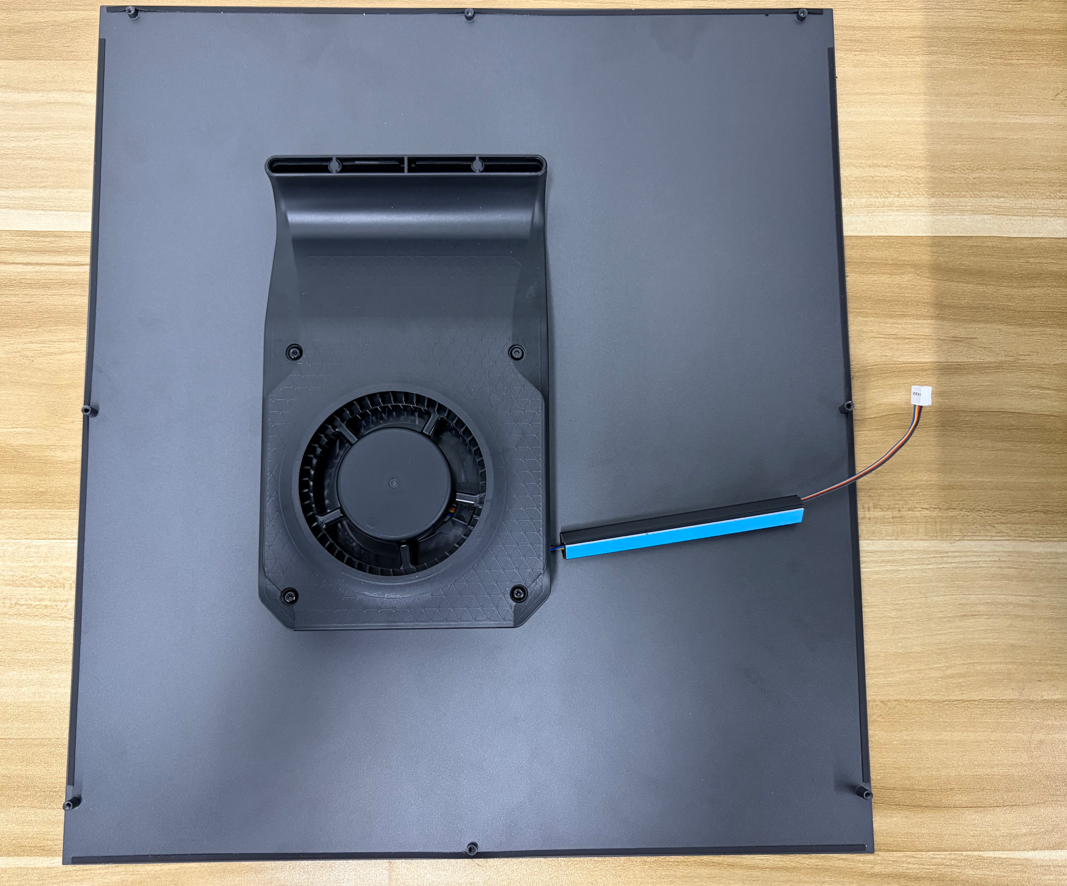
¶ Remove the Adhesive Backing
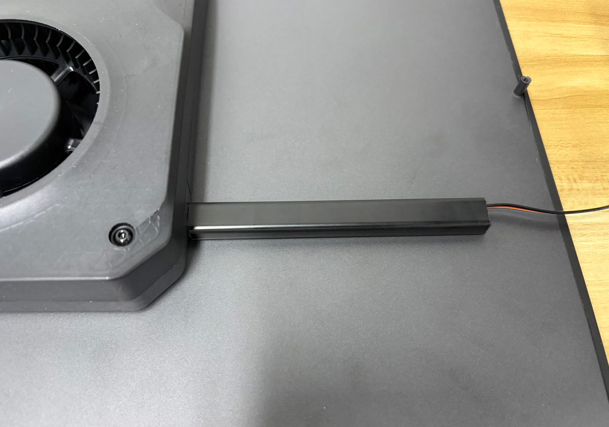
Remove the protective film from the adhesive tape on the back of the cable raceway.
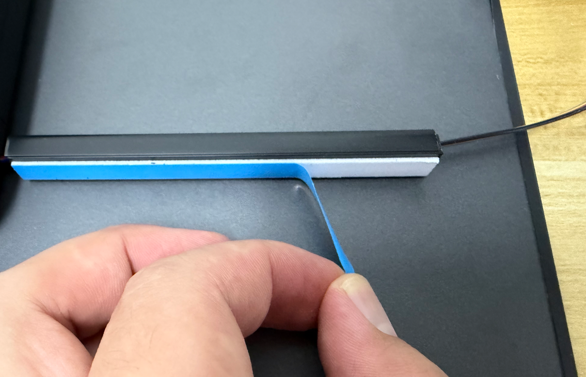
¶ Attach the Cable Raceway
Attach the cable raceway to the surface of the left enclosure panel.
¶ Position the Left Enclosure Panel
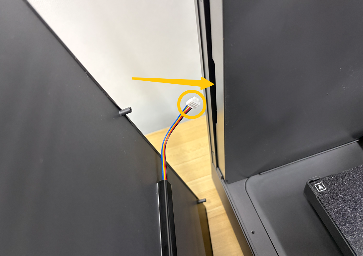
Place the left enclosure panel in position, and route the auxiliary cooling fan connector through the slot along the edge of the printer housing.
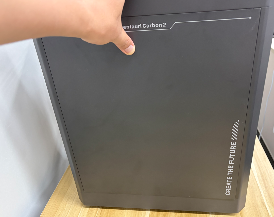
Support the panel by hand to prevent it from falling.
¶ Secure the Left Enclosure Panel
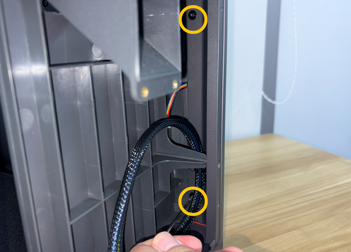
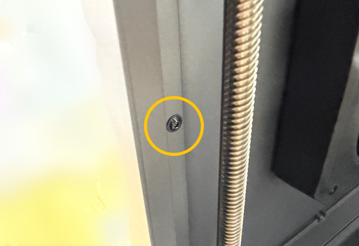
Using a 2.0 mm Allen key, tighten the 6 screws securing the top, front-middle, and rear-lower sections of the left enclosure panel.
Top
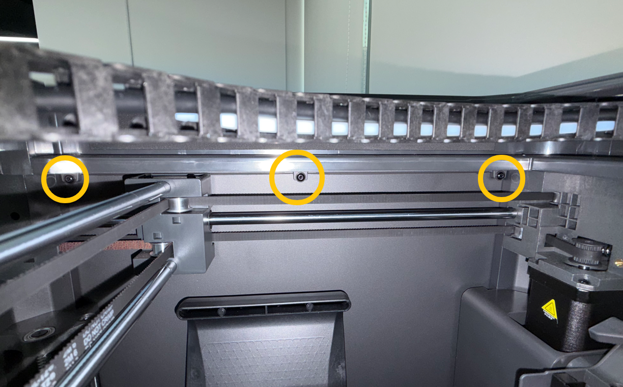
Rear Lower
Front Middle
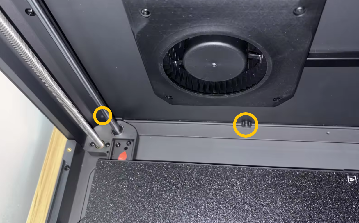
Note
Since the heated bed is positioned at the bottom of the printer, the bottom mounting holes are blocked. Install the bottom screws for both enclosure panels after the printer has completed homing.
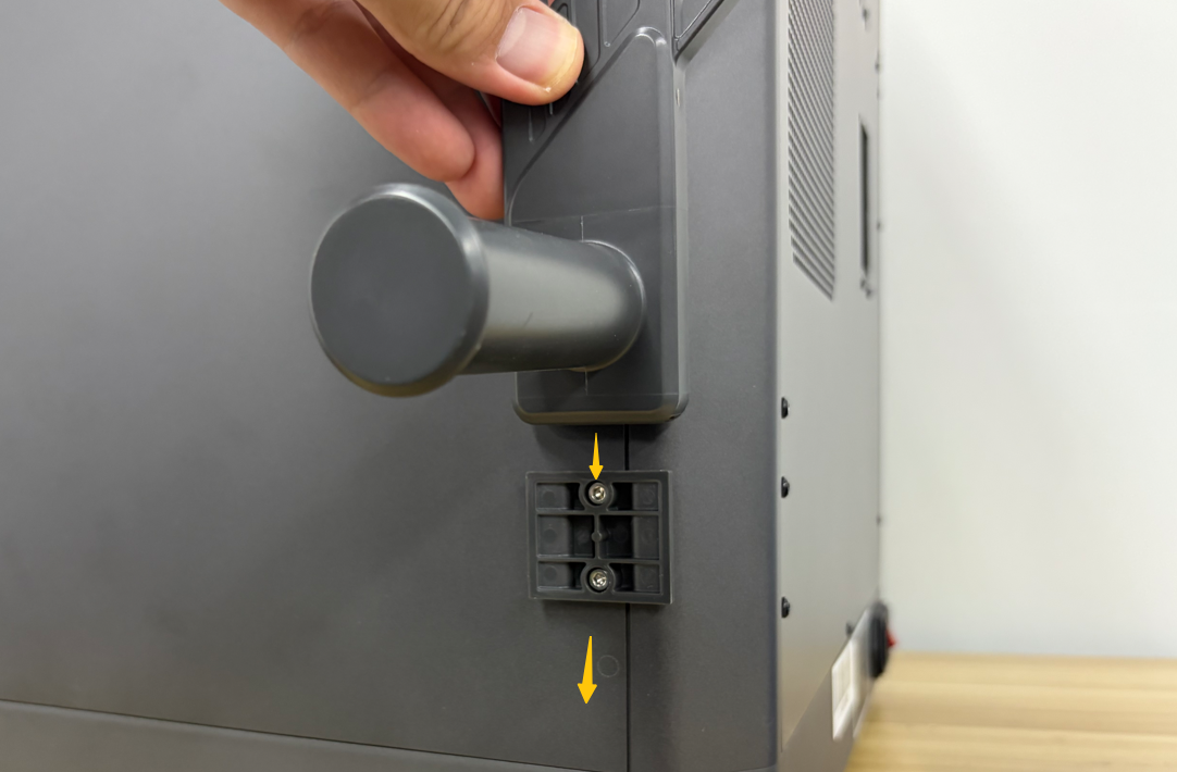
¶ Remove the Spool Holder
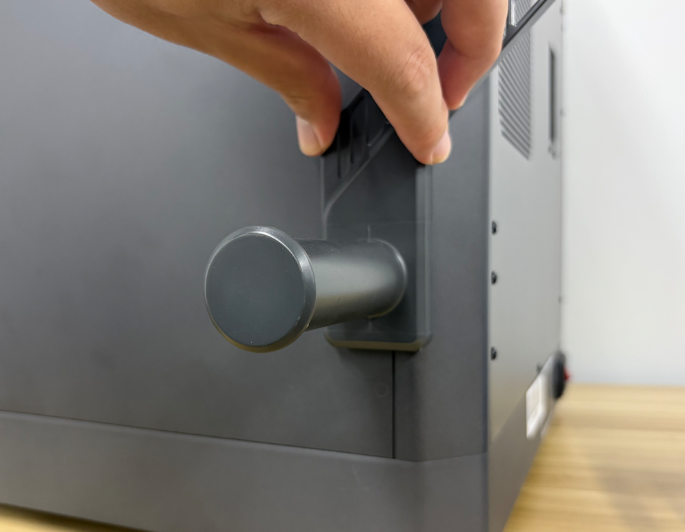
Lift the spool holder upward.
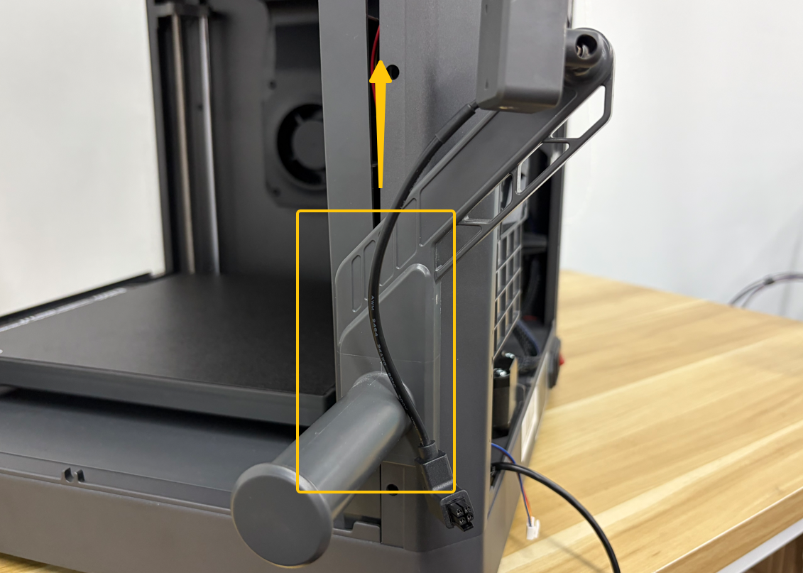
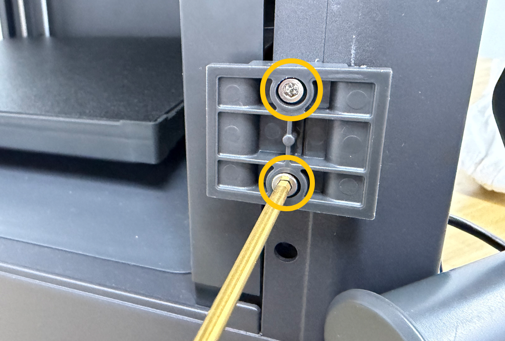
Using a 2.5 mm Allen key, remove the 2 screws securing the spool holder bracket, then remove the bracket.
¶ Install the Right Enclosure Panel
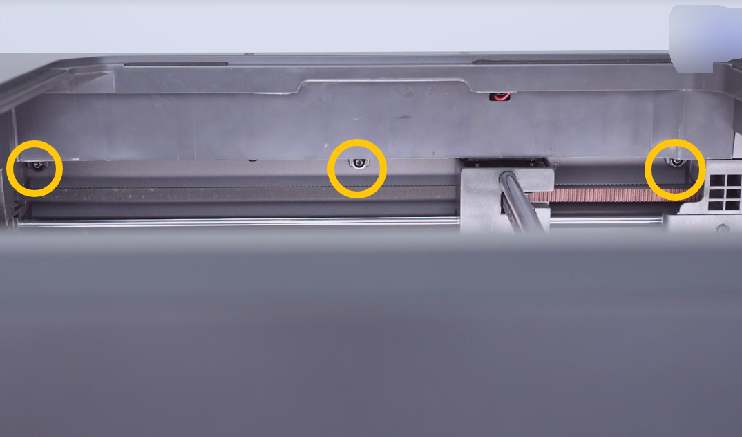
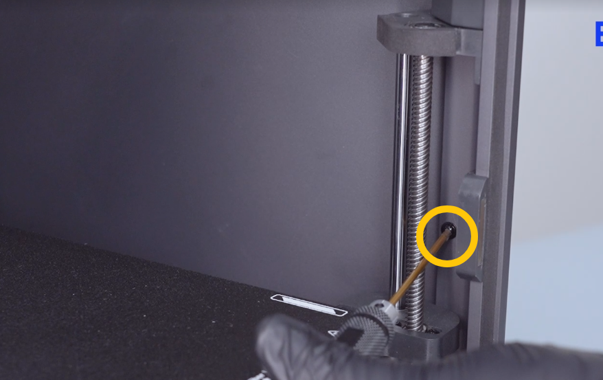
Using a 2.0 mm Allen key, tighten the 6 screws securing the top, front-middle, and rear-lower sections of the right enclosure panel.
Top
Front
Note
Since the heated bed is still positioned at the bottom of the printer, do not install the 2 bottom screws at this stage.
¶ Connect the Cables
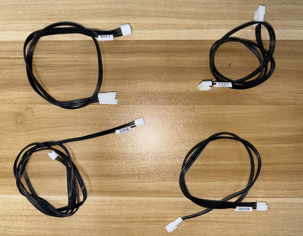
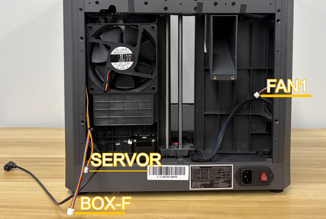
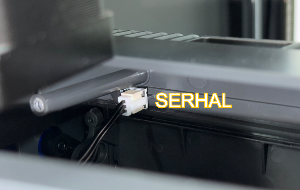
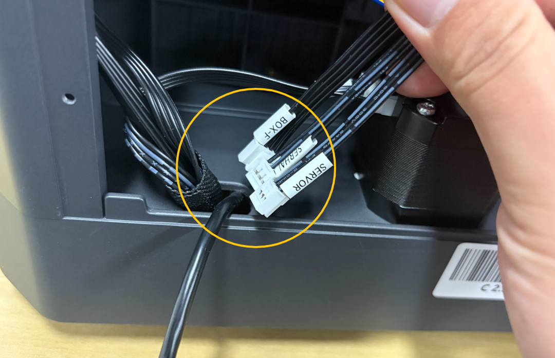
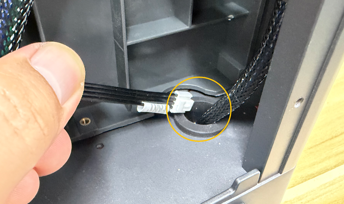
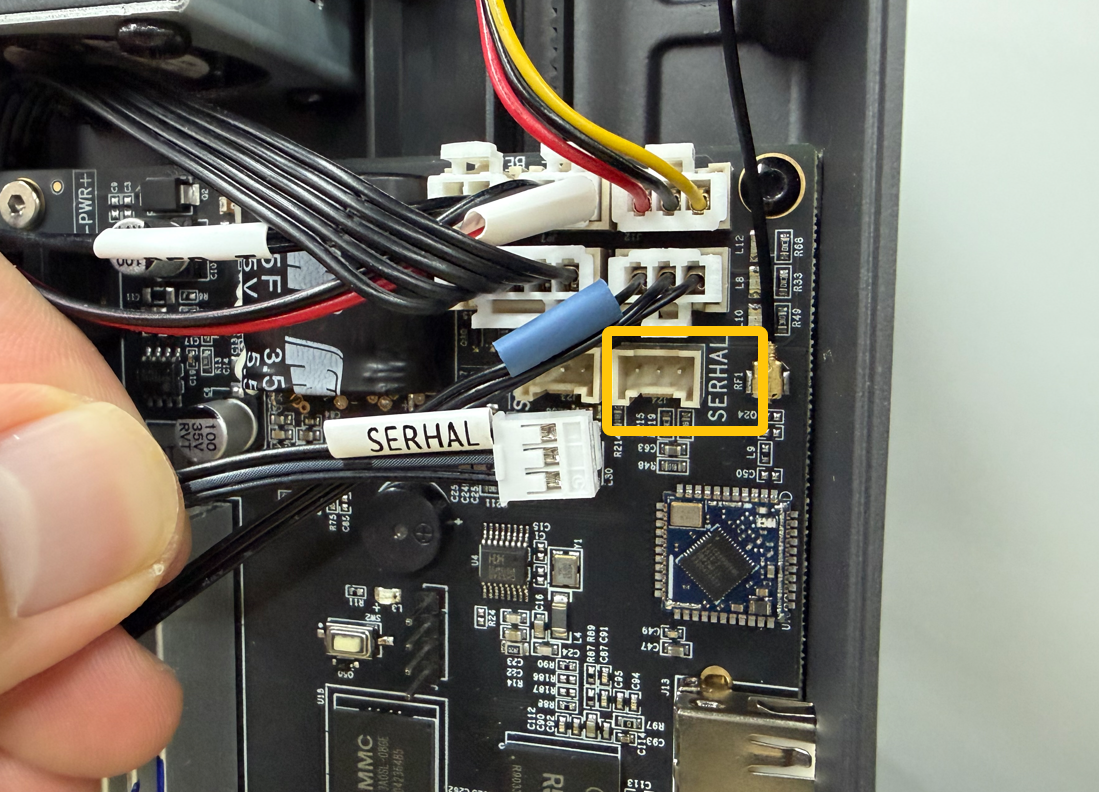
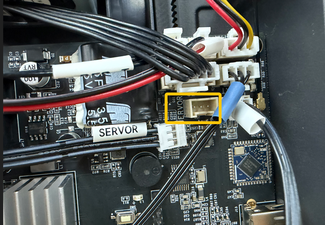
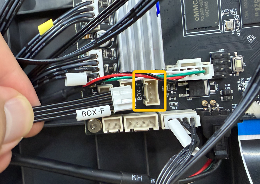
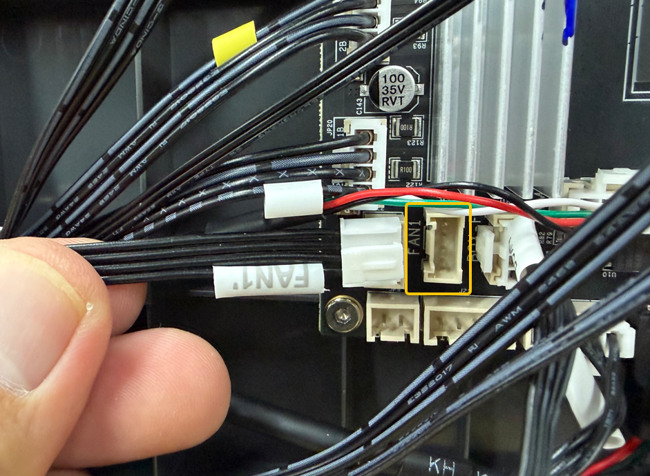
Connect each cable to the corresponding component according to the connector labels.
Open the upper section of the enclosure panel to access the SERHAL port.
Route the SERVOR, SERHAL, and BOX-F connectors through the left-side cable slot.
Route the FAN1 connector through the right-side cable slot.
Turn the printer over and connect each connector to the corresponding port on the mainboard according to the connector labels.
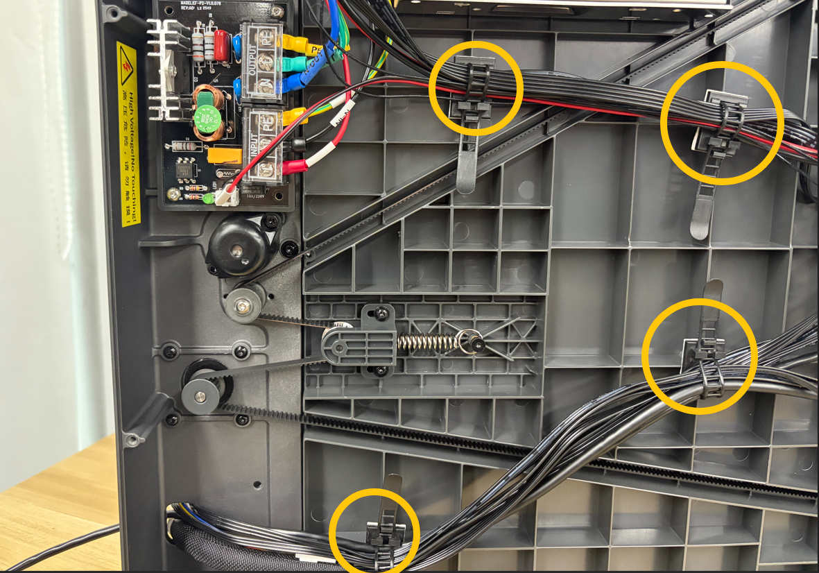
Loosen the cable tie and arrange the cables neatly.
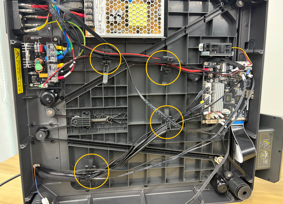
Secure the cables using the cable tie.
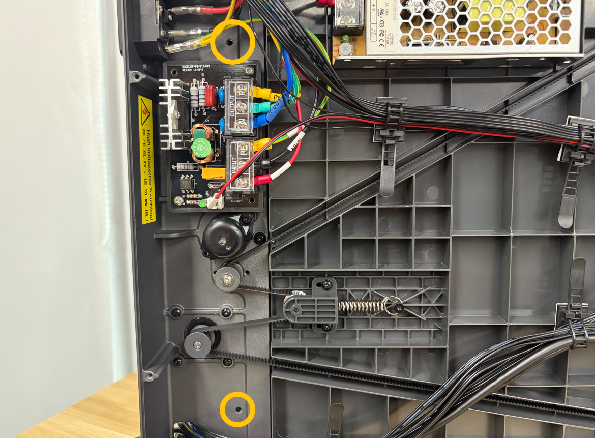
¶ Tighten the Bottom Screws of the Enclosure Panels
Using a 2.0 mm Allen key, tighten the 2 bottom screws securing the enclosure panels.
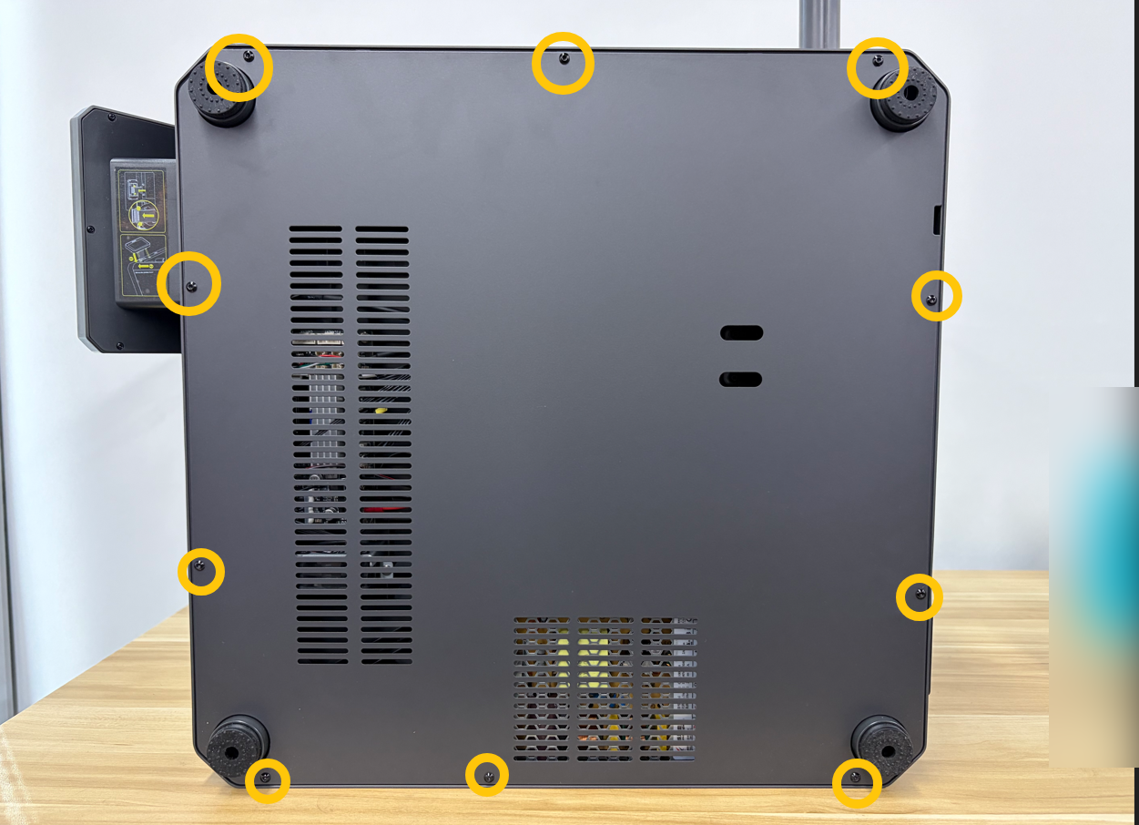
¶ Install the Bottom Cover
Using a 2.0 mm Allen key, tighten the 10 screws securing the bottom cover.
¶ Tighten the Rear Screws of the Enclosure Panels
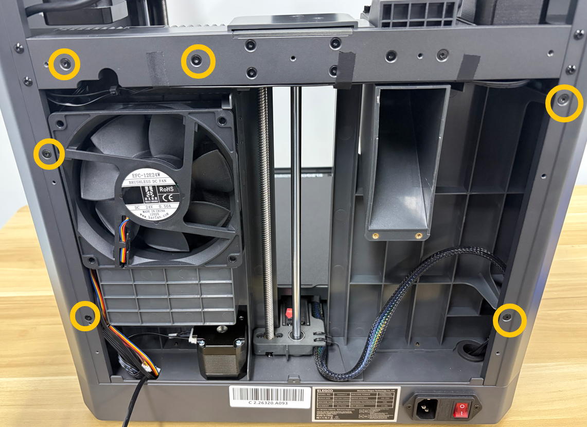
Using a 2.0 mm Allen key, tighten the 6 rear screws securing the enclosure panels.
¶ Tighten the Top Screw of the Enclosure Panels
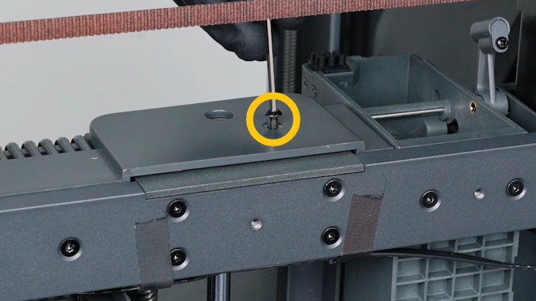
Using a 2.0 mm Allen key, tighten the top mounting screw.
¶ Install the Back Cover
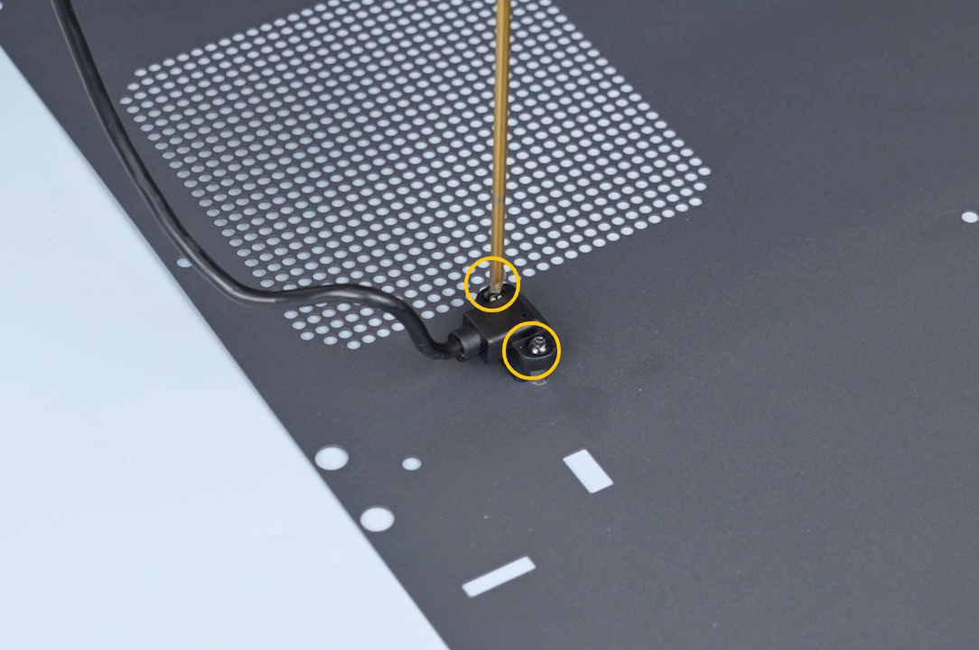
Position the CANVAS Extension Cable Connector in the opening of the back cover, then use a 2.0 mm Allen key to tighten the 2 mounting screws.
Lift the back cover and route the CANVAS Extension Cable through the gap beside the printer cooling fan.
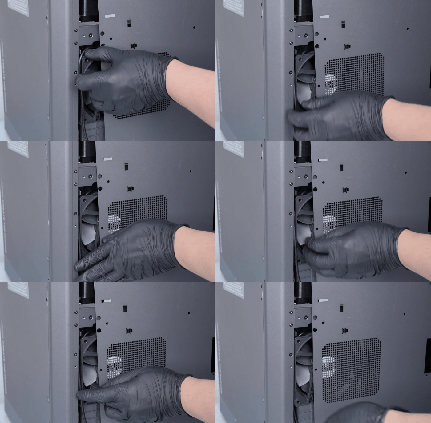
Place the back cover back into position while supporting it by hand.
Using a 2.0 mm Allen key, tighten the 14 screws securing the back cover.
¶ Reinstall the Spool Holder
Connect the filament detection cable to the connector on the back cover.
Position the spool holder bracket, then use a 2.5 mm Allen key to tighten the 2 mounting screws.
Reinstall the spool holder.
¶ Install the Front Door
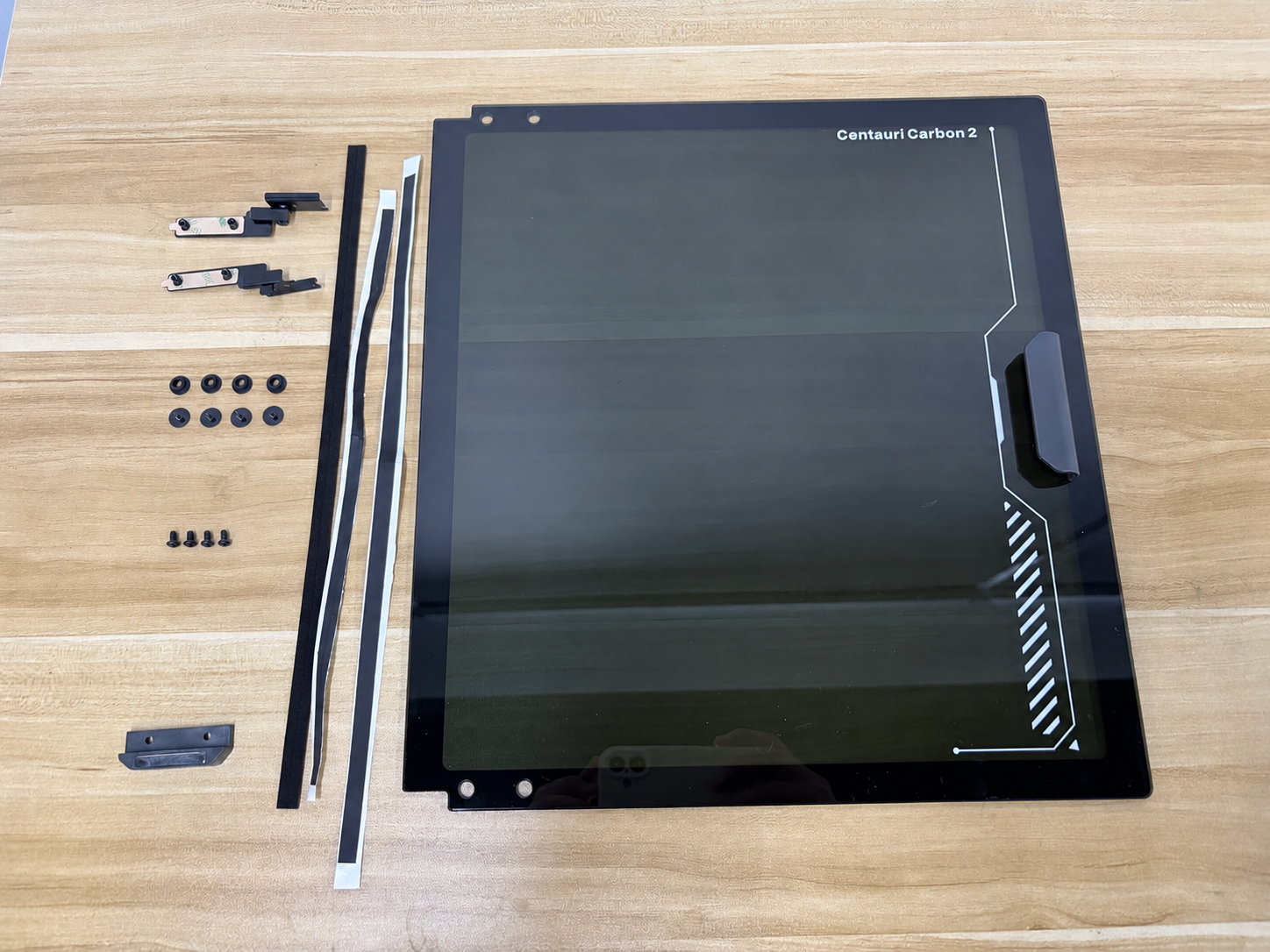
¶ Parts List
- Front Door Glass ×1
- Fine PU Damping Foam for Front Glass Door ×2
- EVA Foam for Front Glass Door ×1
- Lower Damping Hinges ×2
- Large Flat-head Hex Socket Screws ×4
- Glass Door Isolation Pads ×4
- M3×6 Screws ×4
- Front Door Magnetic Assembly ×1
¶ Installation Procedure
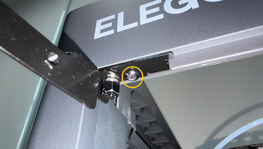
¶ Install the Lower Damping Hinges
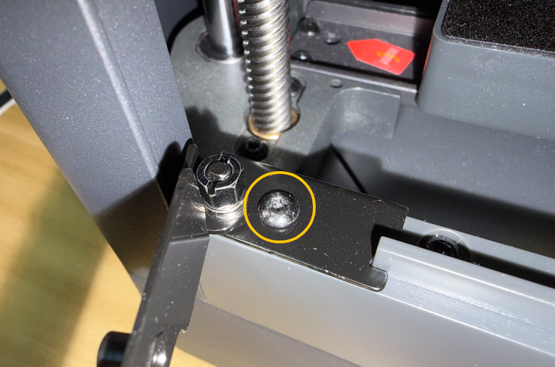
Place the lower damping hinges at the corresponding positions on the upper and lower door frames, then tighten the screws using a 2.0 mm Allen key.
¶ Install the Front Door
Remove the protective backing from the lower damping hinges.
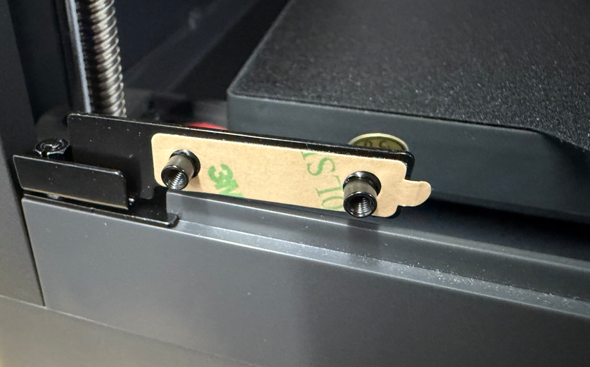
Align the front door with the hinge mounting holes, then place the door into the frame.
Note
Support the glass door by hand during installation to prevent it from falling.
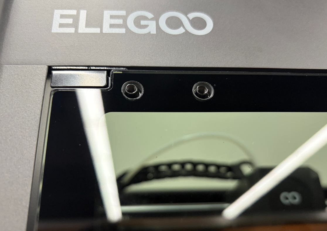
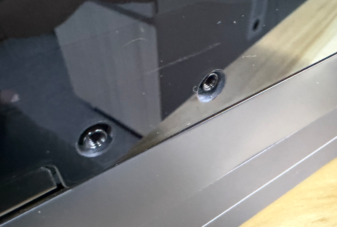
Insert the glass door isolation pads.
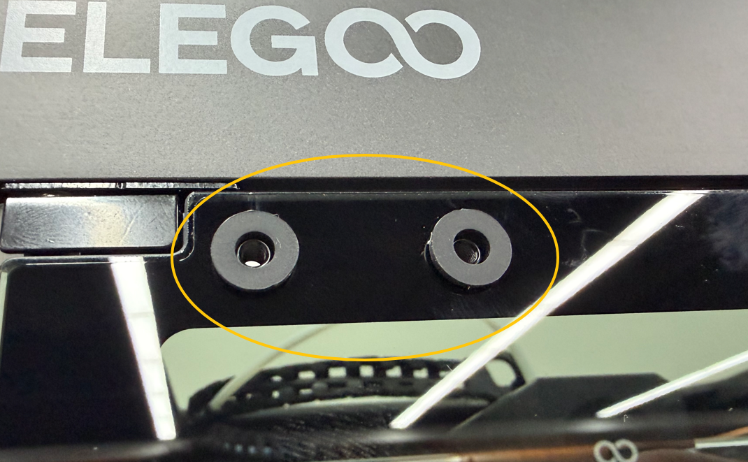
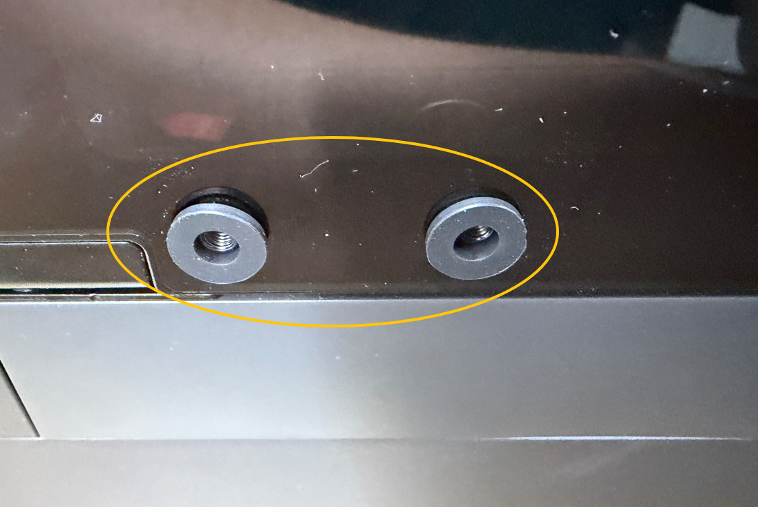
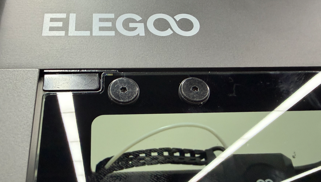
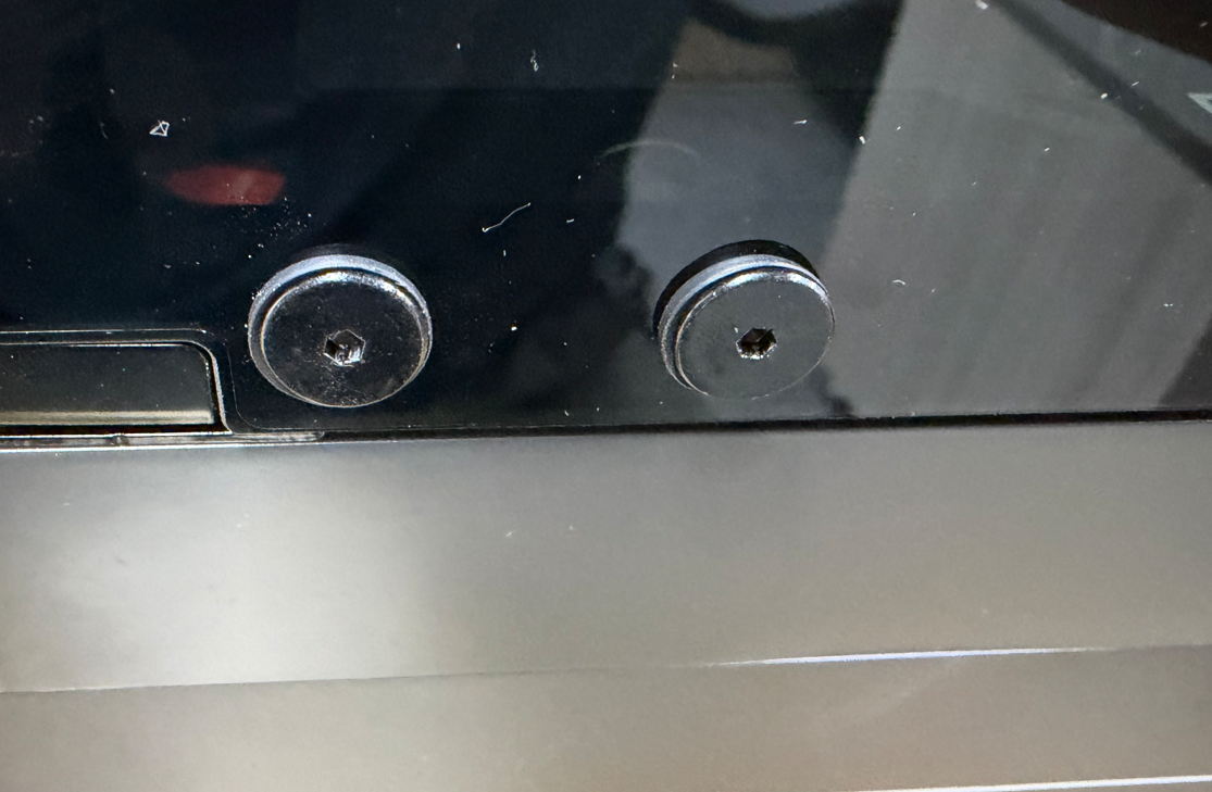
Use a 2.0 mm Allen key to tighten the 4 large flat-head hex socket screws.
¶ Install the Damping Foam
Remove the protective backing from the damping foam.
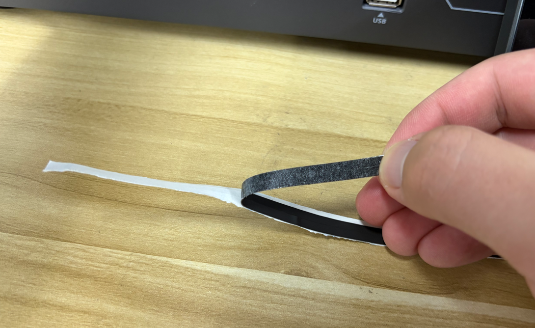
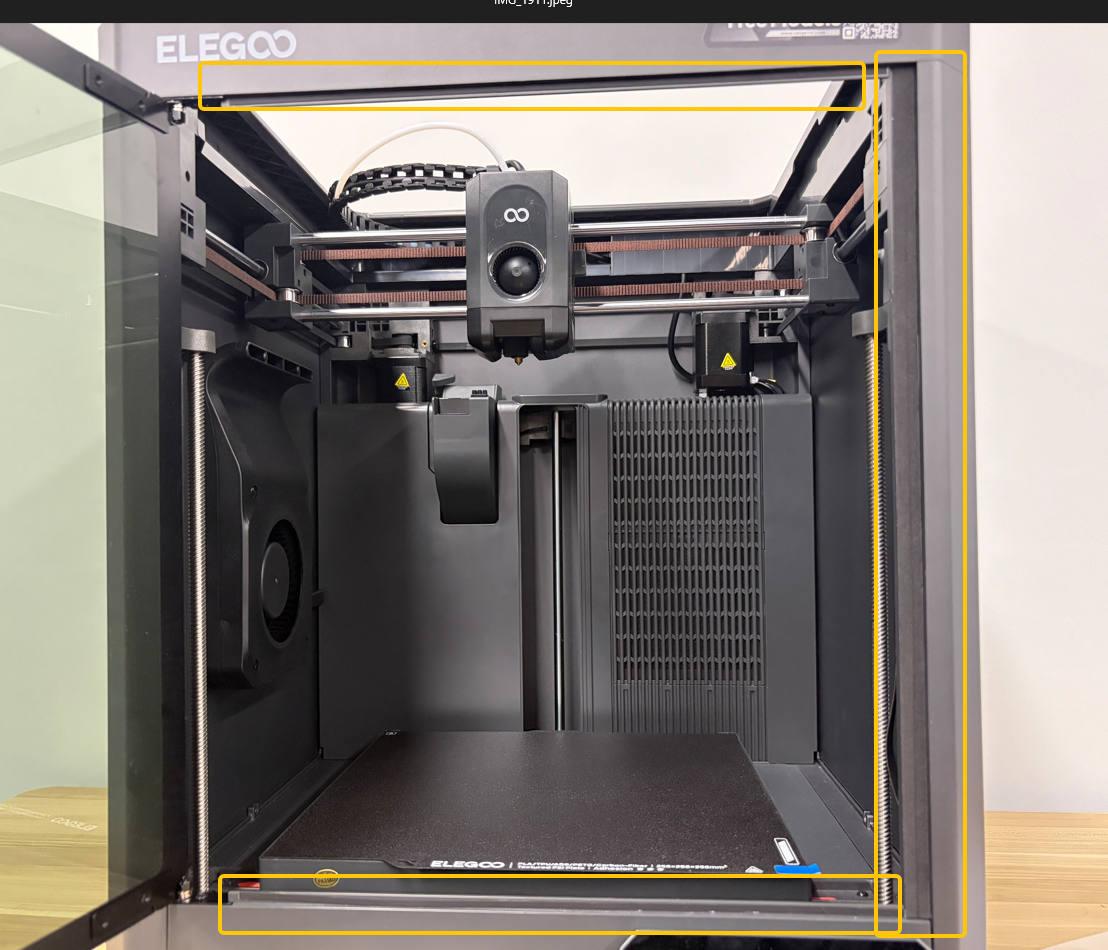
Attach the damping foam to the corresponding positions on the door frame.
¶ Install the Front Door Magnetic Assembly
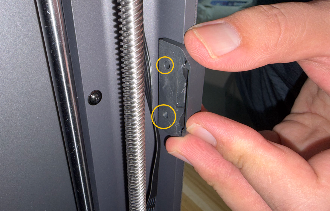
Position the magnetic assembly, then tighten the mounting screws using a 2.0 mm Allen key.
¶ Install the Top Cover
¶ Parts List
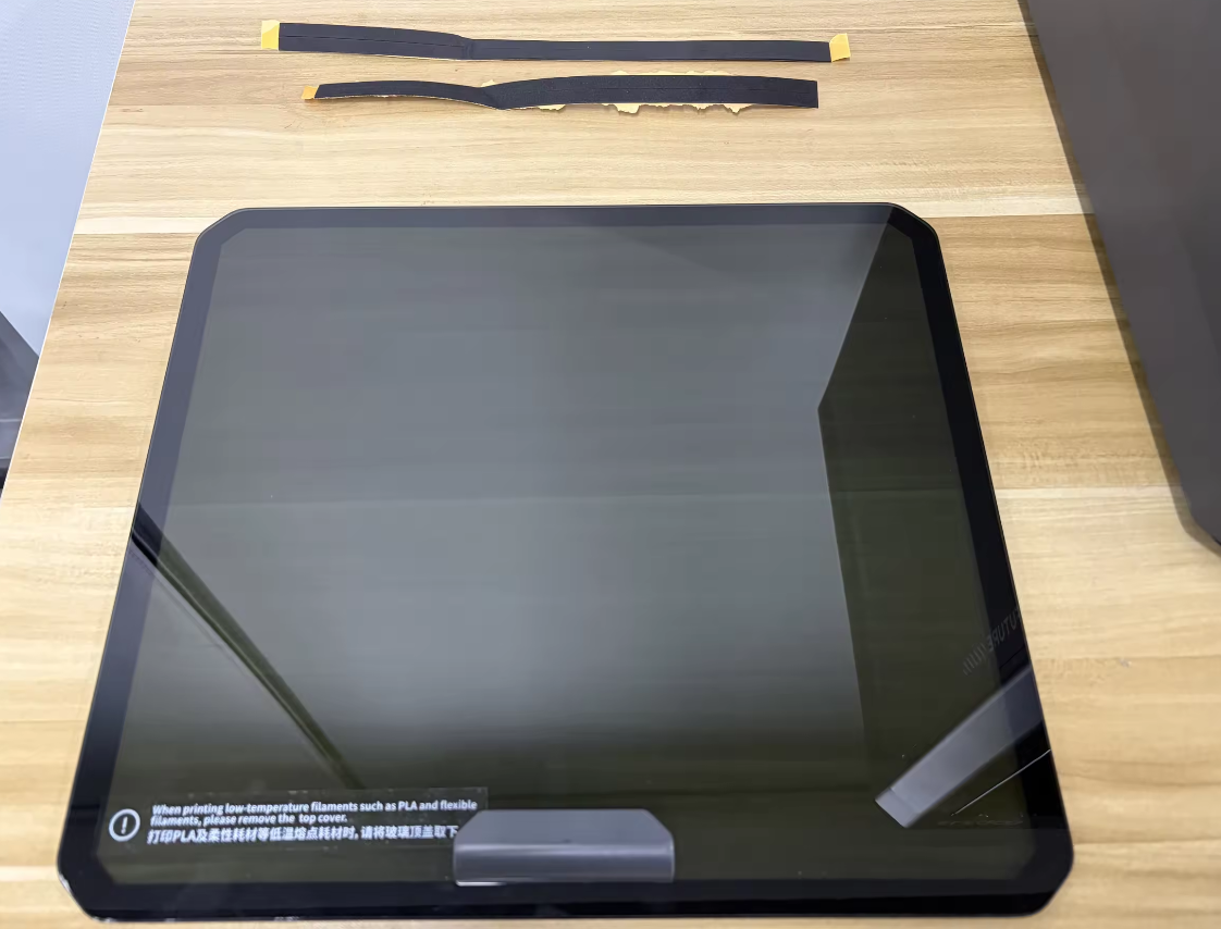
- Centauri Carbon 2 Top Glass Assembly ×1
- Upper Glass Cover EVA Foam A ×2
- Upper Glass Cover EVA Foam B ×2
¶ Installation Procedure
¶ Install the Top Cover
Remove the protective backing from the EVA foam.
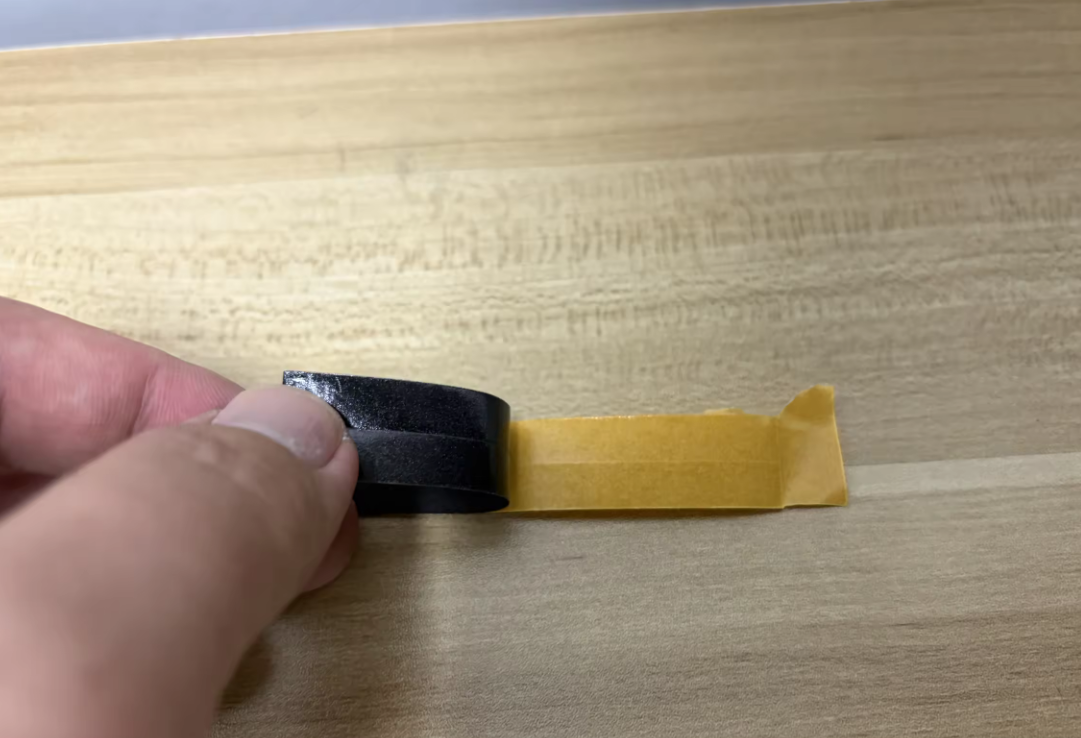
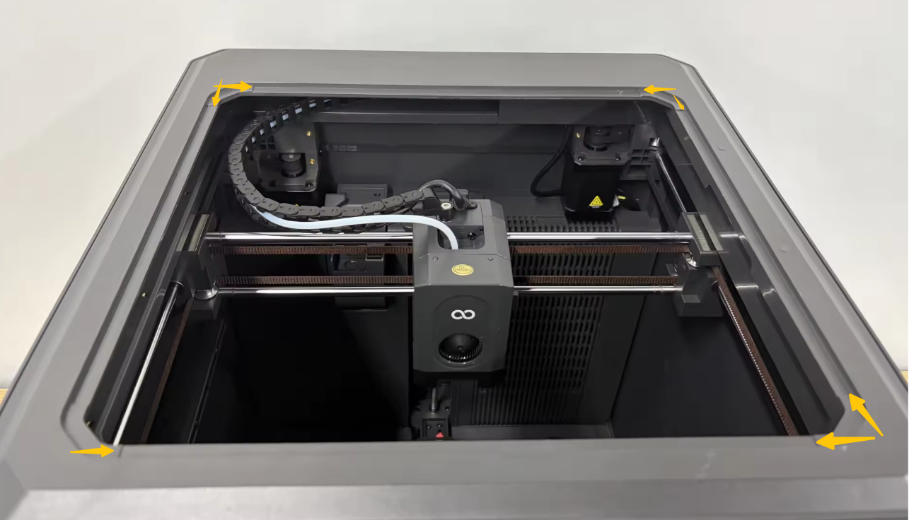
Attach the four EVA foam pieces to the grooves of the upper frame housing in sequence.
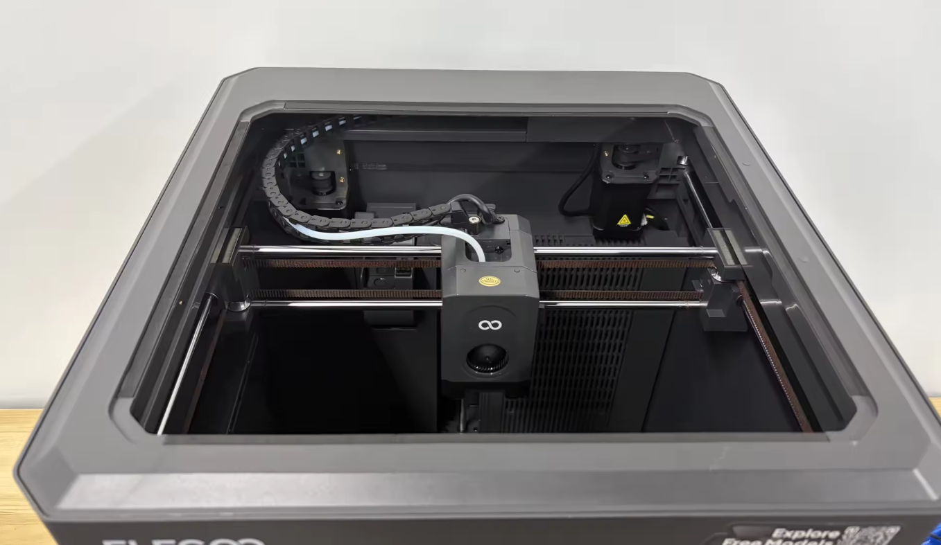
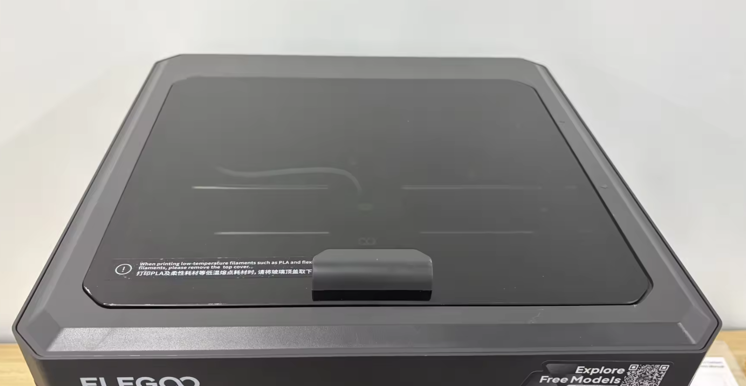
Place the top glass assembly onto the printer.
¶ Touch Screen Settings
Connect the power cord and turn on the printer.
On the touch screen, navigate to:
Settings → Upgrade (Model Upgrade Program)
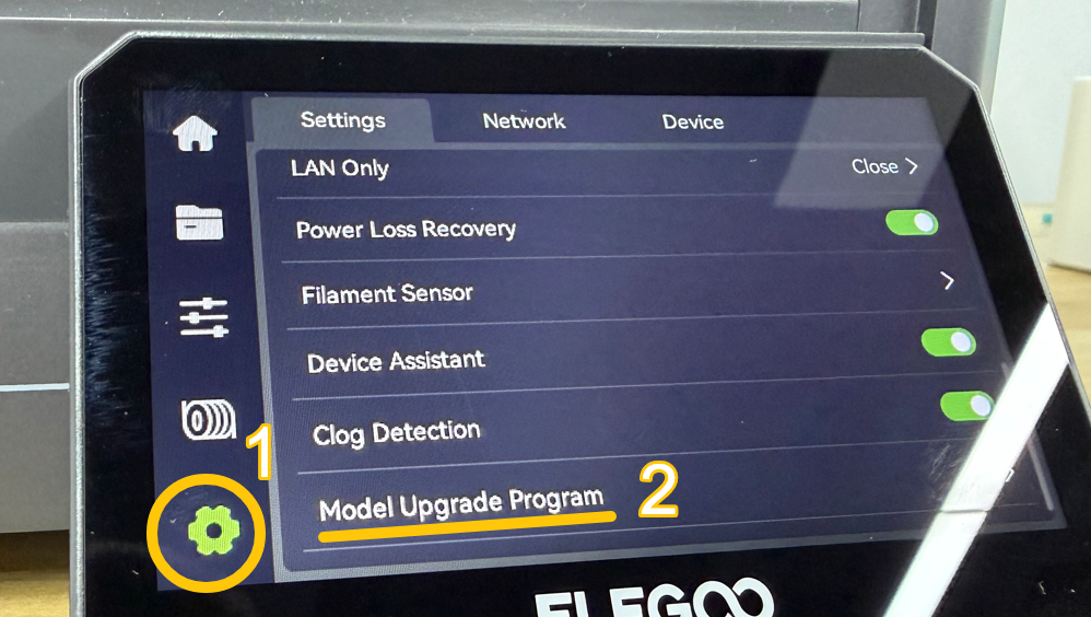
Select:
- Overhead Light
- Camera
- Auxiliary Fan
- Exhaust Vent
- Case Fan
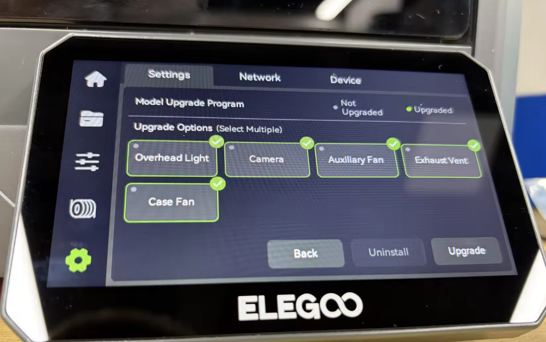
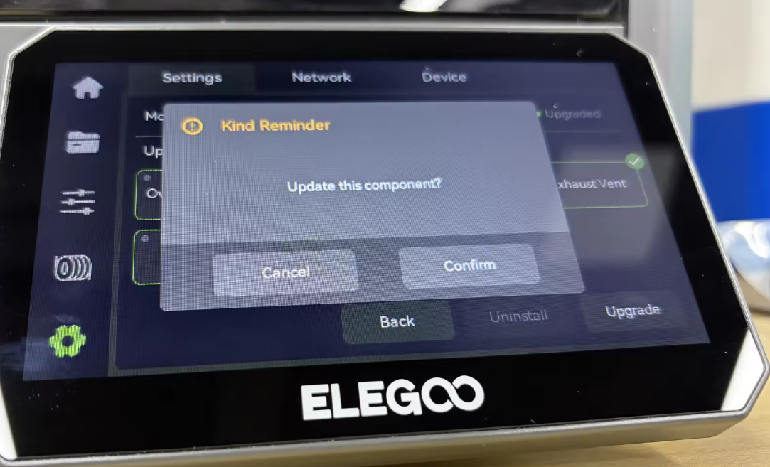
Click Upgrade → Confirm.
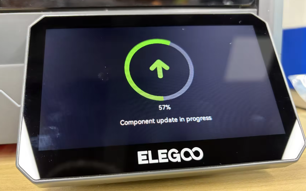
Wait for the printer to complete the upgrade process.
¶ Tighten the Left and Right Enclosure Panel Screws
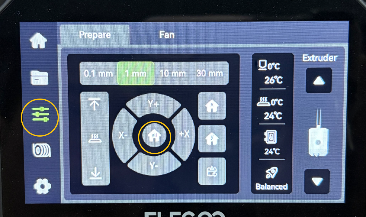
On the touch screen, navigate to:
Control → Home
Wait for the printer to complete homing.
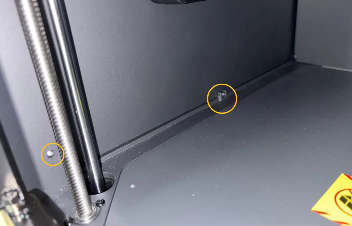
Using a 2.0 mm Allen key, tighten the 4 bottom screws securing the left and right enclosure panels.

¶ Calibration
On the touch screen, navigate to:
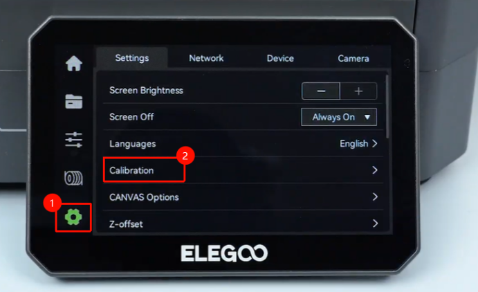
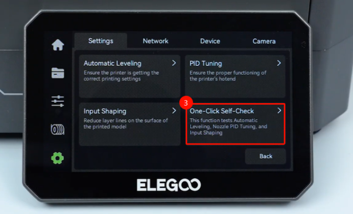
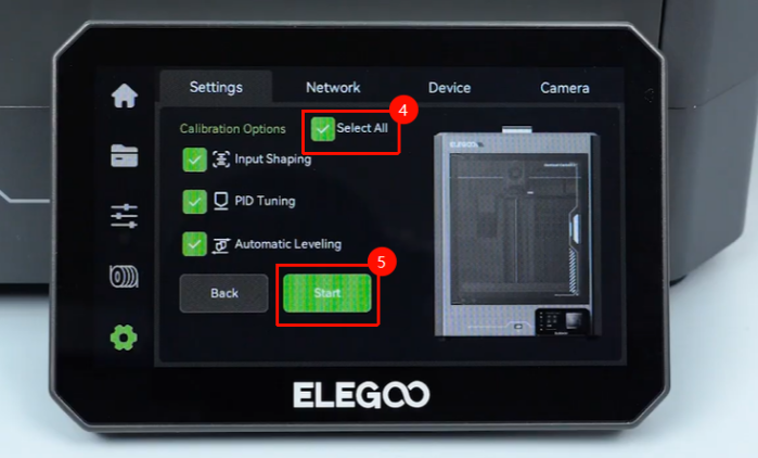
Calibration → One-Click Self-Check → Select All → Start
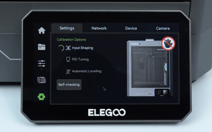
Wait until the printer completes the self-check. The printer is now ready for use.