¶ Tracking-control
In this lesson, we will teach you how to achieve the line-tracking function of the Smart Robot Car V 4.0 and make it move according to the black line we drawn.
If you want to make your own runway, here are some tips for you.
¶ Tips:
The cured part of the line should be as smooth as possible.If the radiusof the turning circle is too small,the car may probably miss the runway.
In addition to line tracking,we can also expand ourimagination todevelop other program according to the theoretical of line tracking.Forexample,we can develop a program that confine the car to an arearegardless of its movement.
¶ Main text
In our kit,the line-trackingfunction is achieved by the tracking module,and the tracking module is consisted of three photoelectric sensorandother electric components.
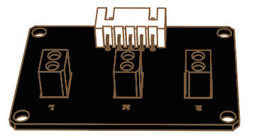
Please open the folder of last level for details:Related chip information->ITR20001 and SmartRobot-Shield。
The photoelectric sensoris composed of an infrared pair tube(transmitting/receiving)and an NPN silicon phototransistor,which is equipped with a lightsource and an optical receiving device.The light emitted by the light sourceis received by the photosensitive element through the reflection of theobject to be measured,and then the required information is obtainedthrough the processing of relevant circuits. It can be used to detect thechange of ground light and shade and color,as well as detect the presenceorabsence of close objects.
let's see which pin the three photoelectric sensors connect to and then we can start writing program.
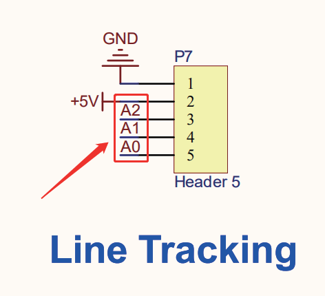
Please openTB6612 -> Demo1 in the current folder.
First of all, let’s define the related pins and variables:/in /DeviceDriverSet_xxx0.h
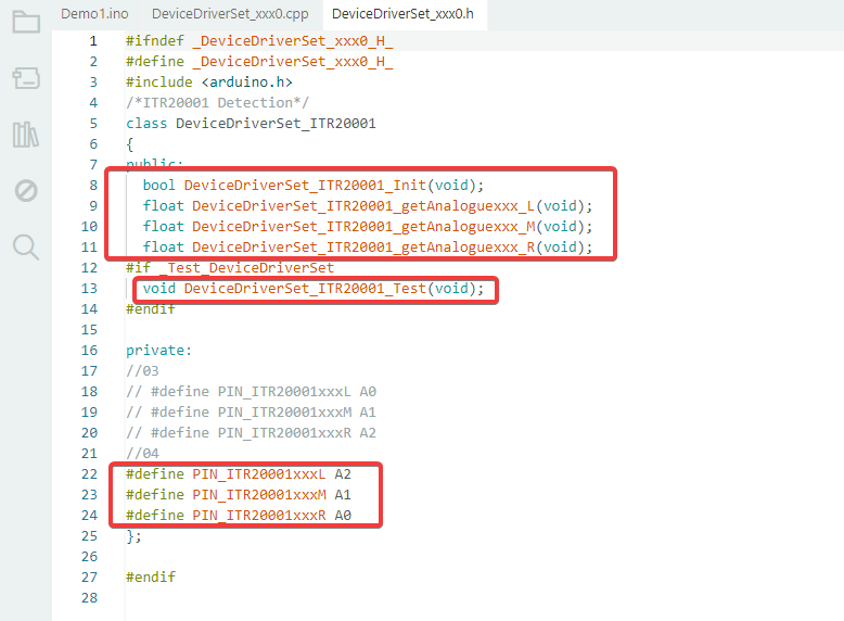
This is the header file for 3-channel IR line-tracking sensor ITR20001. It declares the class, functions, and sensor pins for external use.
Defines a class DeviceDriverSet_ITR20001 that encapsulates all sensor operations.
Init(): Initialize the sensors
getAnaloguexxx_L(): Read left sensor analog value
getAnaloguexxx_M(): Read middle sensor analog value
getAnaloguexxx_R(): Read right sensor analog value
Defines pins for three IR sensors: Left:A2 Middle: A1 Right:A0
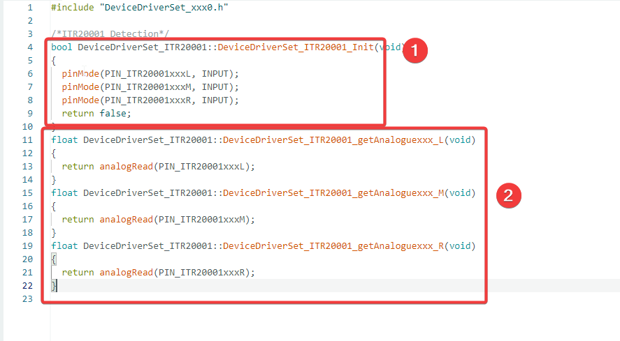
After declaring the functions in the header file, the next step is to write the specific implementation (function definition) of these functions in the .cpp source file. /in /DeviceDriverSet_xxx0.cpp
We can divide the .cpp source file into two parts:
- one part is the sensor initialization function.Set left, middle, and right IR sensor pins to INPUT mode so the Arduino can read sensor signals.
- and the other part is the sensor data reading function.Read the analog value of the corresponding sensor via the analogRead(PIN) function, return the result for subsequent program use.
Upload the program.(Please toggle the“Upload-Cam” button to “Upload”when uploading the program.)After the program has been uploadedsuccessfully,please open the serial port and you will see the data of the threephotoelectric sensors fluctuates around 1000.And if you block one of thephotoelectric sensors with your hands, the corresponding detected valuewill be greatly reduced.
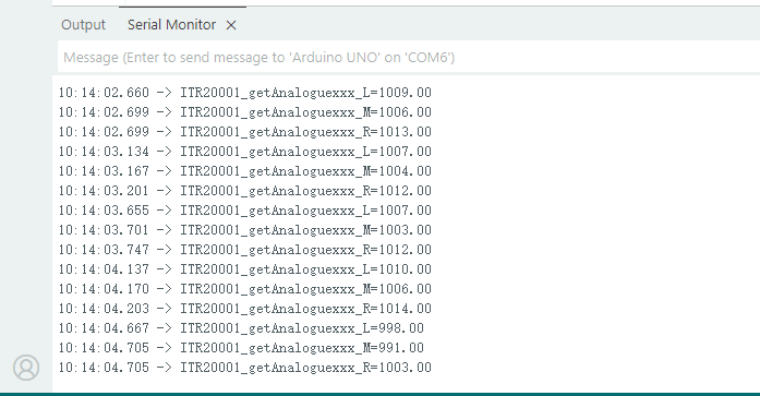
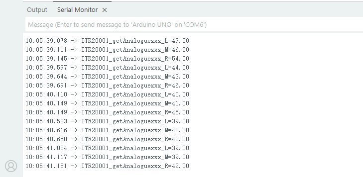
The above two sets of data show the output values of the line-tracking sensors when suspended in the air and when white paper is placed in front of them. It can be seen that the reading is about 1000 when the sensors are suspended, while the value is generally lower than 100 when facing white paper. We can set a trigger threshold for line tracking. If the sensor value is lower than the preset value, it means the sensor is above the white ground area.
After learning the previous courses, we have mastered the use of photoelectric sensor. Next, we are going to achieve the tracking function by combining the car's movement function learned in the lesson 2 and the photoelectric sensor.
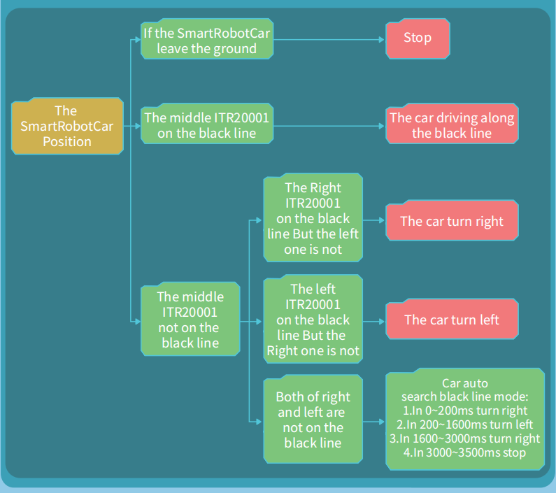
At the beginning, let’s look at the whole flow chart of the tracking mode.
Please open Demo2 in the current folder:
First of all, let’s take a look at the relative definition of tracking function.//in ApplicationFunctionSet_xxx0.h
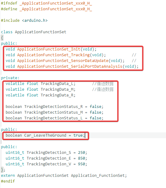
This file declares the application-level class for the car, including:
Line tracking functions
Sensor data update
Line-tracking variables (L / M / R)
Thresholds for line detection
Car ground detection flag
Key Functions:
Init(): Initialize motors, sensors, MPU6050.
Tracking():Main line-tracking function to follow the black line.
SensorDataUpdate():Update left, middle, right sensor values in real time.
Most people will go straight to check the CPP files at this stage. Without solid technical basics, you can hardly understand the code and sort out its logic. So what are more effective ways to solve this problem?
You can analyze step by step through the call hierarchy, and understand the code by following the program logic.
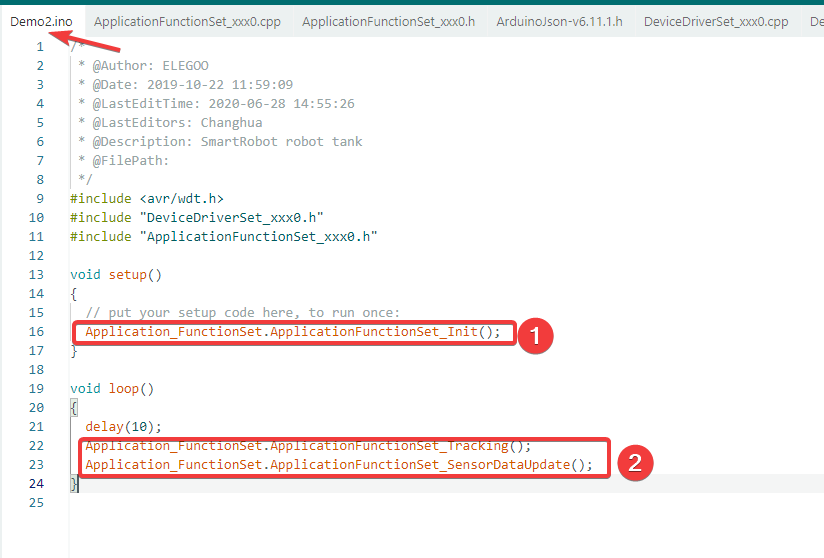
Click on demo2.ino, and you will see the code as shown in the figure.
It contains two functions:setup() and loop().
The setup() function calls an init() function to initialize specific data.
The loop() function calls two functions: line-tracking and sensor data update.You only need to open the corresponding called functions to check their implementation details.
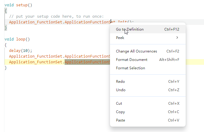
In most cases, you can hover your mouse over the corresponding function, hold down the Ctrl key and right-click. A pop-up menu will appear; click "Go to Definition" to view the function definition.
If the jump fails, select and copy the function name, switch to the associated .cpp file, and press Ctrl + F to search for it.
¶ Initialization Function ApplicationFunctionSet_Init()
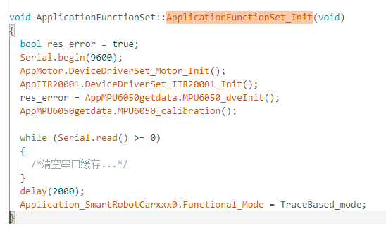
Function : Initialize all hardware devices and set working mode once after system power-on
Execution Flow :
-
Hardware Initialization (call 4 driver initialization functions in sequence)
- Serial.begin(9600) — Initialize serial communication for debugging output
- AppMotor.DeviceDriverSet_Motor_Init() — Initialize motor driver, configure pin modes
- AppITR20001.DeviceDriverSet_ITR20001_Init() — Initialize tracking sensors, configure A0/A1/A2 as input pins
- AppMPU6050getdata.MPU6050_dveInit() — Initialize MPU6050 attitude sensor
- AppMPU6050getdata.MPU6050_calibration() — Calibrate MPU6050 gyroscope
-
System Preparation
- Clear serial buffer ( while(Serial.read() >= 0) )
- Delay 2 seconds for system stabilization ( delay(2000) )
-
Working Mode Setting
- Set Application_SmartRobotCarxxx0.Functional_Mode = TraceBased_mode (tracking mode)
¶ Tracking Function ApplicationFunctionSet_Tracking()
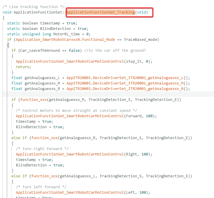
Function : Core tracking algorithm that controls the car to follow black lines based on three IR sensor readings
Execution Flow :
-
Pre-checks
- Check if current mode is tracking mode ( Functional_Mode == TraceBased_mode )
- Call ApplicationFunctionSet_SmartRobotCarLeaveTheGround() to detect if car is off ground. If yes, call ApplicationFunctionSet_SmartRobotCarMotionControl(stop_it, 0) to stop movement
-
Read Sensor Data
- Call AppITR20001.DeviceDriverSet_ITR20001_getAnaloguexxx_L() to read left sensor (A2 pin)
- Call AppITR20001.DeviceDriverSet_ITR20001_getAnaloguexxx_M() to read middle sensor (A1 pin)
- Call AppITR20001.DeviceDriverSet_ITR20001_getAnaloguexxx_R() to read right sensor (A0 pin)
-
Black Line Position Judgment & Action Execution (use function_xxx() to check if value is within threshold 250-850)
- Middle sensor detects black line → Call ApplicationFunctionSet_SmartRobotCarMotionControl(Forward, 100) to move forward
- Right sensor detects black line → Call ApplicationFunctionSet_SmartRobotCarMotionControl(Right, 100) to turn right
- Left sensor detects black line → Call ApplicationFunctionSet_SmartRobotCarMotionControl(Left, 100) to turn left
- No sensor detects black line → Enter blind search mode (swing left/right to find black line)
¶ Sensor Data Update Function ApplicationFunctionSet_SensorDataUpdate()
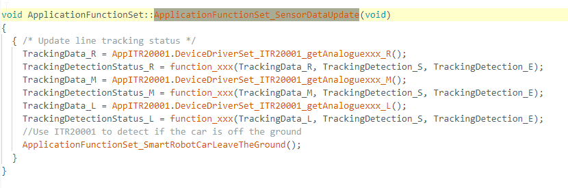
Function : Periodically update tracking sensor status and ground detection flag
Execution Flow :
-
Read and judge three sensor states
- Right sensor: TrackingData_R = AppITR20001.DeviceDriverSet_ITR20001_getAnaloguexxx_R() → TrackingDetectionStatus_R = function_xxx(TrackingData_R, 250, 850)
- Middle sensor: TrackingData_M = AppITR20001.DeviceDriverSet_ITR20001_getAnaloguexxx_M() → TrackingDetectionStatus_M = function_xxx(TrackingData_M, 250, 850)
- Left sensor: TrackingData_L = AppITR20001.DeviceDriverSet_ITR20001_getAnaloguexxx_L() → TrackingDetectionStatus_L = function_xxx(TrackingData_L, 250, 850)
-
Ground Detection
- Call ApplicationFunctionSet_SmartRobotCarLeaveTheGround() to update Car_LeaveTheGround flag
¶ Motion Control Function ApplicationFunctionSet_SmartRobotCarMotionControl()
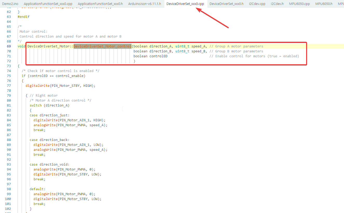
Function: Control left/right motors based on direction commands, supporting 9 motion states
Core Call:
- Ultimately calls
AppMotor.DeviceDriverSet_Motor_control()for low-level motor control
Motion Direction Table:
| Direction Constant | Action | Calling Method |
|---|---|---|
| Forward | Move Forward | ApplicationFunctionSet_SmartRobotCarMotionControl(Forward, 100) |
| Backward | Move Backward | ApplicationFunctionSet_SmartRobotCarMotionControl(Backward, 100) |
| Left | Turn Left | ApplicationFunctionSet_SmartRobotCarMotionControl(Left, 100) |
| Right | Turn Right | ApplicationFunctionSet_SmartRobotCarMotionControl(Right, 100) |
| LeftForward | Left Forward Arc | ApplicationFunctionSet_SmartRobotCarMotionControl(LeftForward, 100) |
| LeftBackward | Left Backward Arc | ApplicationFunctionSet_SmartRobotCarMotionControl(LeftBackward, 100) |
| RightForward | Right Forward Arc | ApplicationFunctionSet_SmartRobotCarMotionControl(RightForward, 100) |
| RightBackward | Right Backward Arc | ApplicationFunctionSet_SmartRobotCarMotionControl(RightBackward, 100) |
| stop_it | Stop | ApplicationFunctionSet_SmartRobotCarMotionControl(stop_it, 0) |
Upload program.(Please toggle the“Upload-Cam” button to “Upload”when uploading the program.) After uploading,put the car on the black line,the car will move along the black line. Otherwise, it will enter blind searchmode to look for the black line,it will turn left and right first,and then revolveto the left.