¶ Introduction:
In this lesson, we will teach you the functions and specific usagesof all the remaining components.
¶ First, the use of WI-FI module.
-
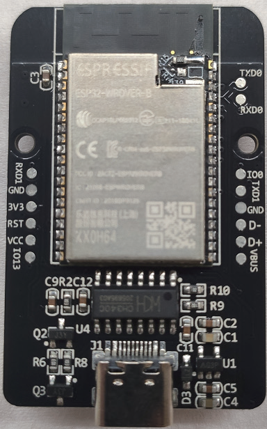
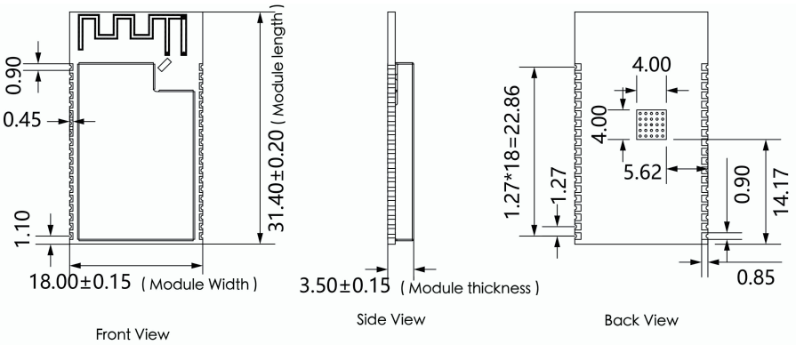
Wi-Fi can simply be understood as wireless communication aris one of the most widely used wireless network transmission technologies today Compared to Bluetooth, Wi-Fi has a wider coverage area, faster transmission speed, and is capable of many-to-many communication. In our kit, the Wi-Fi module is soldered on the ESP32 board. As the Wi-Fi module driveer is complex to use, we are worried that users will have a bad experience cdue to improper operation, so we have already soldered the Wi-Fi moduile and camera module on the ESP32 before leaving the factory, and we won'teach this part of the ESP32 for now.
-
The specific process is to use the Wi-Fi module of the ESP32 to ofpen the Wi-Fi hotspot, and send the information through the APP after thhe phone has connected to the hotspot. The information was sent out through the Wi-Fi module of the phone and then received by the Wi-Fi module of the ESP32. Since we have set the Wi-Fi module to pass-through mode before leaving the factory, the acquired data received by the Wi-Fi moduleof the ESP32 is transferred to the serial port of the ESP32. And since theserial port on ESP32 is connected to the serial port on UNO, we just need to read tThe serial port on the UNO to get the data from the APP.
-
As for the program of UNO, we obtain the string by reading the data received in the serial buffer, and then parse the string. The key infformation is extracted through the fixed format of the string, and the flag biis set according to different key information, and different functions are selected to be called to realize the corresponding function.
-
For specific communication instructions, please check out "Communication protocol for Smart Robot Car' in the "04 Related chip information" folder.
¶ Code Analysis
Now, please open Demo1 in the current folder:
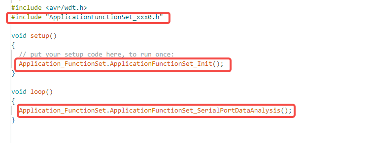
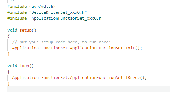
The setup() function calls the Application_FunctionSet.ApplicationFunctionSet_Init() function, and the loop() function calls the ApplicationFunctionSet_SerialPortDataAnalysis function.
Accordingly, we can first check the corresponding header files.
¶ header file
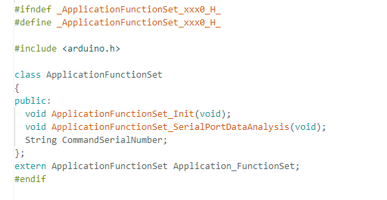
- Member variable: CommandSerialNumber
- Type: String (Arduino String)
- Purpose: Stores the command serial number received from the serial port (the H field in JSON data)
- Global Object Declaration:extern ApplicationFunctionSet Application_FunctionSet;
- Declares Application_FunctionSet as a global object in the .h (header) file.
- The actual definition resides in the .cpp file (ApplicationFunctionSet Application_FunctionSet;).
- Allows other files to access this global object by including this header file.
¶ CPP File
Although the ApplicationFunctionSet_SerialPortDataAnalysis function code in the .cpp file may seem quite lengthy, it essentially consists of only two steps: data reception and data verification.
As shown in the figure below, after collapsing the corresponding code blocks, you can see that the code is actually composed of two if statements, which correspond to the data reception and verification mentioned above.
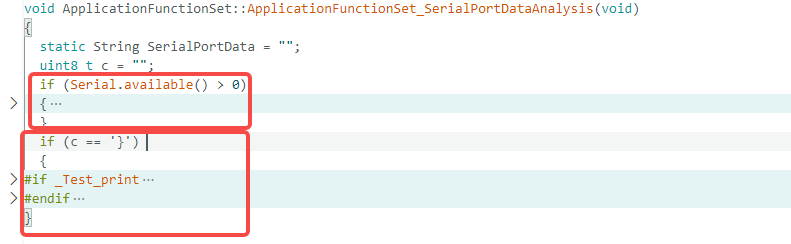
Data Reception Section:
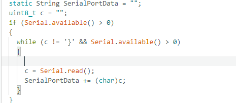
- static String SerialPortData: A static variable whose lifespan lasts throughout the entire program runtime, used to accumulate received data.
- Serial.available(): Checks if there is data available to read in the serial buffer.
- Serial.read(): Reads one byte of data from the serial port.
- while (c != '}'): Frame end delimiter check – uses } as the end marker for the JSON data frame
data verification:
if (c == '}')
{
// Data frame complete, enter parsing phase
}
A frame of data is considered complete only when the end delimiter '}' is received, preventing the parsing of incomplete data.
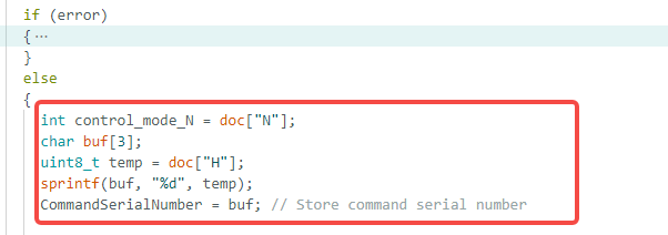
After obtaining the command successfully, the command neecis to be parsed.
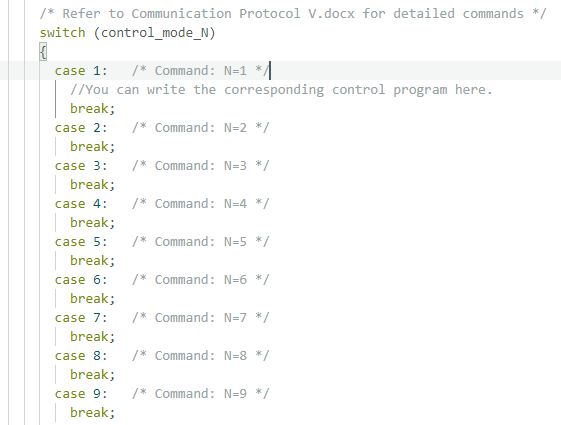
Each case represents one mode, and we just need to put in the functionswe have implemented in the previous few lessons to realize the APP switching function.
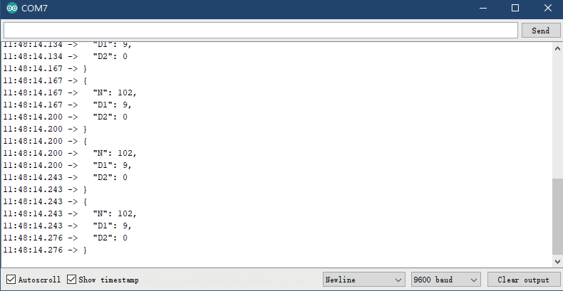
Upload program. (Please toggle the "Upload-Cam" button to "Uplload when uploading the program.) After the program has been uploaded successfully, please do not disconnect the USB cable. Turn the "Uploaad-Cam button to "Cam", and then open mobile' s APP and connect to thee car. When the connection is complete, operate the button in the APP casually. By this time, open the serial port monitor in the Arduino IDE and you will find that every operation you do on the APP will send a string to the car, and the car will perform the corresponding function according to these in:structions.
¶ Second, the use of keys.
We can also switch functions by the key on our Smart Robot Car.
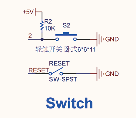
Please open the folder in the previous level for more details: Related chip information -> SmartRobot-Shield.pdf
As we all know, the key is connected to the pin D2 on the UNO.
Next, please open Demo2:
Follow the method of Demo1 above, first check what functions are contained in the main program demo and which functions are called.
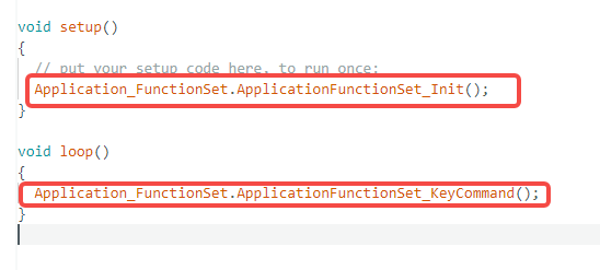
As can be seen from the diagram, demo2.ino calls two functions in Application_FunctionSet. Since only these two functions are declared in the .h file without any other declarations, we can directly view the corresponding function definitions in the .cpp file.
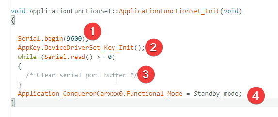
First, looking at the Init function, we can see that it defines :
- the serial baud rate as 9600,
- initializes the key device driver,
- clears the serial buffer, and
- the initial state of the smart car to standby mode.
The Init function of DeviceDriverSet is called here. If you are interested, after understanding the current cpp content, you can check which variables or functions are initialized inside it, and which functions are called.
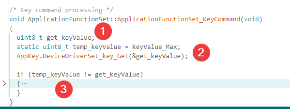
Next, let’s examine the specific definitions inside the ApplicationFunctionSet_KeyCommand function. Following the previous method, first observe the overall structure. After folding the code, we can see that the function is divided into three parts, as shown in the figure:
- first, define a variable temp_keyValue to store the previous key value;
- then obtain the current key value via AppKey.DeviceDriverSet_key_Get;
- finally, detect changes in the key state through if conditional judgments.
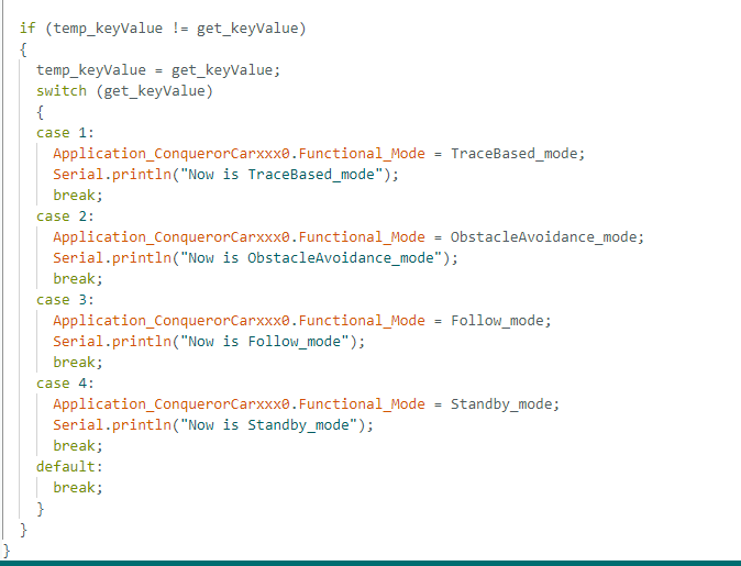
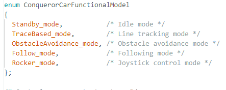
After expanding the if structure, you can see that the program assigns the currently acquired key value to the old key value, executes conditional judgments based on the key value, and then calls the corresponding motion mode (while outputting relevant information via the serial port). The judgment logic here uses members of the Application_ConquerorCarxxx0 struct/object for comparison, which has been defined at the top of the current cpp file.
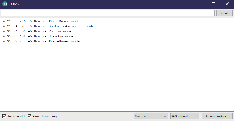
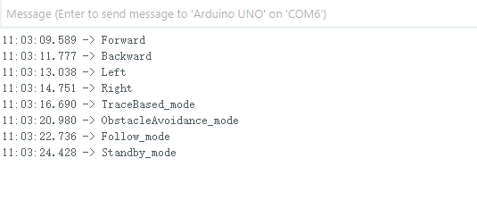
Upload program. (Please toggle the "Upload-Cam" button to "Uploaad" when uploading the program.) After the program has been uploaded successfully, please open the serial port and press the key, you will see the statement that switches to different functions is displayed on thee serial port Since our focus in this section is on the use of keys, we only print outhe current switched mode statement on the serial port and do not implement the corresponding specific function, but you can add different functions according to the previous lessons.
Due to project version iterations, some library files may differ, which may cause the code of legacy users to fail to run and display effects properly. If you encounter situations where functions cannot be implemented, you can click the download button to obtain the revised and improved program files.
¶ Third, the use of infrared receiving and transmitting module.
Other than pressing keys to switch functions, we can also switclthe functions of our Smart Robot Car through infrared remote control since we have applied the infrared receiving module.
Please open the folder in the previous level for more details: Relatedchip information -> Smart Robot-Shield.pdf
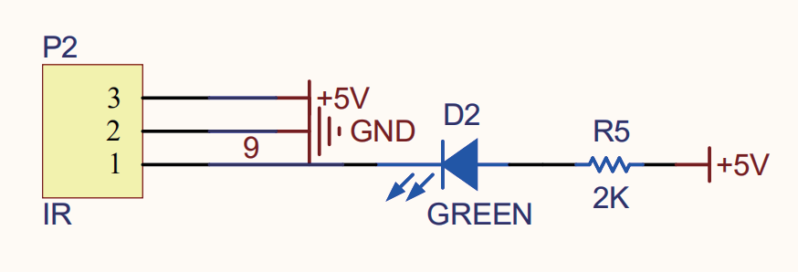
As shown in the figure, the infrared receiving module is connectedto pin D9 of UNO, and we also connected it to a green LED light. When we press tThe key of the remote control, if the infrared receiving module receives the signal, the LED light will turn on.
Infrared remote control is mainly composed of infrared transnhitter and infrared receiver.
The signals transmitted and received by infrared are actually aa series of binary pulse codes, and the high and low levels change accordingto a certain time rule to transmit corresponding information. In order to protect it from interference from other signals during wireless transmission, the signal is usually modulated on a specific carrier frequency (38K infrareed carrier signal) and transmitted through an infrared emitting diode, while the infrared receiving end needs to decode and adjust the signal, and then restore it to binary pulse code for processing.
Next, please open Demo3:
The operation method here is the same as before, so it will not be repeated. We will directly proceed to the explanation of the function definition.
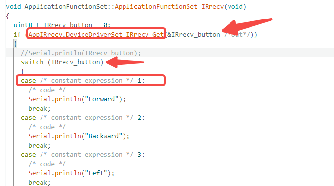
In the ApplicationFunctionSet_IRrecv function, it can be seen that it mainly performs two operations:
- first, it calls DeviceDriverSet_IRrecv_Get to obtain the pressed key value from the remote control,
- and then executes the corresponding actions based on the acquired key value.
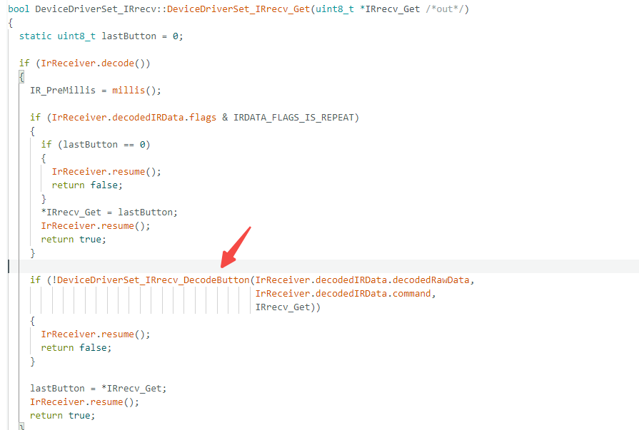
The DeviceDriverSet_IRrecv_Get function is called here. You can find this function in the DeviceDriverSet_xx.cpp file and check its specific function definition and calling relationships. As shown in the figure below, this function internally calls the infrared key decoding function DeviceDriverSet_IRrecv_DecodeButton, where you can view the decoding logic for the corresponding keys.
Upload program. (Please toggle the "Upload-Cam" button to "Upload"when uploading the program.) After the program has been uploaded successfully, please open the serial port and press the key, you will see the statement that switches to different functions is displayed on the seerial port .
Since our focus in this section is on the use of keys, we only print out the current switched mode statement on the serial port and do not implemhent the corresponding specific functions, but you can add different function according to the previous lessons.
Due to project version iterations, some library files may differ, which may cause the code of legacy users to fail to run and display effects properly. If you encounter situations where functions cannot be implemented, you can click the download button to obtain the revised and improved program files.
¶ Forth, voltage detection.
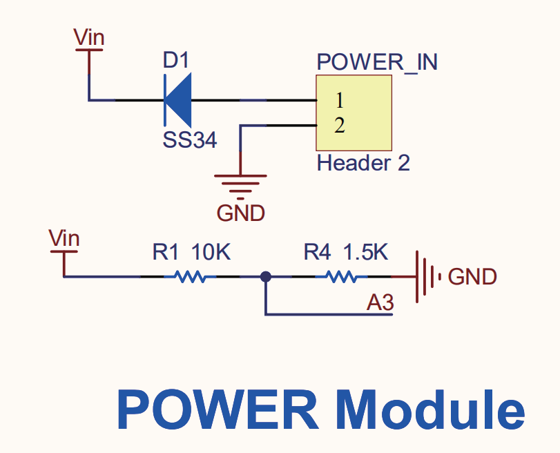
In order to prevent damage to the battery caused by excessive discharge ,voltage must be monitored. So we'll teach you how to measure the battery voltage now.
Now, please open Demo4:
Firstly, we need to initial the pin we used.
void voltageInit()
{
pinMode(VOL_MEASURE_PIN, INPUT);
}
Then calculate the power supply voltage according to the formula.
Vout =(Vin×R2)/(R1 + R2)
Then collect the value of A3 through the analogRead() function, vwe know that the Arduino controller has multiple 10-digital modular conversion channels. This means that Arduino can map voltage input signalsof 0-5V to a value of 0-1023.
In other words, we can divide the 5V signal into 1024 equal parts, the OV input signal corresponds to the value 0, and the 5Vt input signal corresponds to 1023.
To achieve voltage monitoring, it is not enough to use the analogRead() function to read the A3 value. We also need to convert this read value into an actual voltage value, so we can use the followingformula for conversion:
Battery voltage V = A3 read value * (5.00 / 1024.00) * multiplier
To sum up:
Battery voltage V = A3 read value *(5.00 / 1024.00) * ((R1 + R2)/R2)
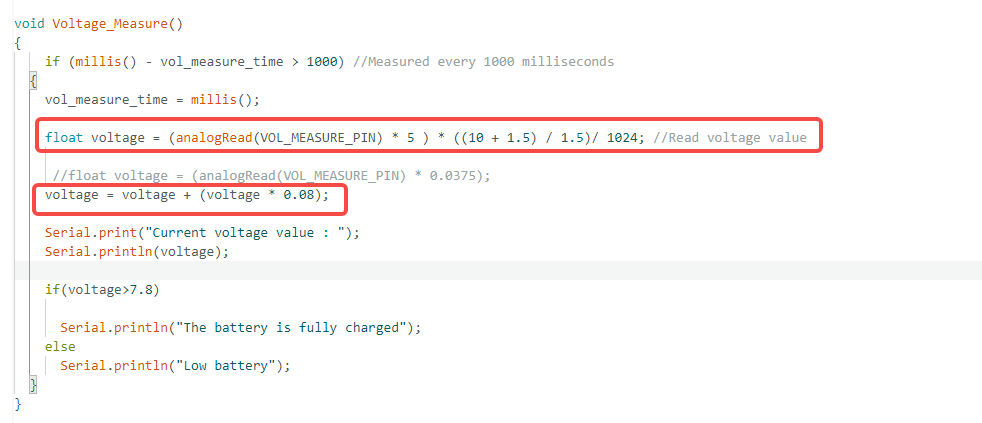
float voltage = (analogRead(VOL_MEASURE_PIN) * 5 ) * ((10 + 1.5) / 1.5)/ 1024; //Read voltage value
Since the data might be overlooked by the software and errors might occur if the decimal is too large when the data is dividing by 1024, we'd better divide the data by 1024 at the end.
Battery voltage V = A3 read value *(5.00) * ((R1 + R2)/R2) / 1024.00
Finally, we will need to correct the error.
Battery voltage V =Battery voltage V+ (Battery voltage V* 0.08)
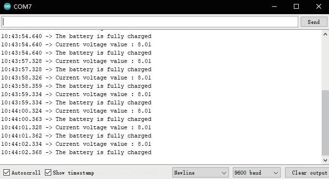
Upload program. (Please toggle the "Upload-Cam" button to "Upload"when uploading the program.) After the program has been uploaded successfully, please open the serial port and you will see the currenvoltage value.
¶ The last one, the use of RGB colored light.
We will teach you how to turn on the colored light on the car and changer its brightness and color.
In our kit, the realization of lighting effects uses the WS2812B modulel ,WS2812B is an intelligent externally controlled LED light source integrating a control circuit and a light-emitting circuit. The data protocol adopts a single-wire return-to-zero code communication method. After thee pixel is powered on and reset, the DIN terminal receives the data transrmitted from the controller.
The first 24bit data sent over is extracted by the first pixel and sent to the data latch inside the pixel, the remaining data is shaped and amplified by the internal shaping processing circuit and then forwarded through the DO port to start outputting to the next cascade of pixel, and the signal is reduced by 24bit for each pixel that passes through thetransmission.
The pixel adopts the automatic shaping and forwarding technology, so that the number of cascades of the pixel is not limited by the signal tranismission, but only by the signal transmission speed requirements. LED has the advantages of low voltage drive, environmental protection and energy-saving, high brightness, large scattering angle, good consistency, ultra-low power, and ultra-long life. Integrating the control circuiton the LED makes the circuit simpler and smaller in size, and easier to install.
Please open the folder in the previous level for more details: Related chipinformation -> SmartRobot-Shield.
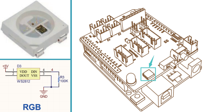
It can be seen from the figure that the RGB colored light is connected to the D4 pin of UNO.
This is an Arduino program that uses the FastLED library to control an RGB LED and implement a smooth color gradient cycle. The program cycles through colors in the sequence Red → Green → Blue → Red, creating a natural and fluid color transition effect on the LED.
First, check what settings are configured in the setup.
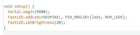
Function Description:
- Initialize the serial port for debug output.
- Configure the NEOPIXEL type LED driver; the number of LEDs can be set via the num_led parameter.
- Set the global brightness to 20 (approximately 8% brightness to avoid excessive glare).
Then check what functions are defined in the Color function。
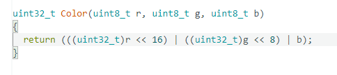
Core Principle: Pack three independent 8-bit RGB components into a 32-bit integer.
- r (red): (uint32_t)r << 16, occupying the high 16 bits
- g (green): (uint32_t)g << 8, occupying the middle 8 bits
- b (blue): b, occupying the low 8 bits
Example:
- Pure Red Color(255, 0, 0) → Result: 0x00FF0000
- Pure Green Color(0, 255, 0) → Result: 0x0000FF00
- Pure White Color(255, 255, 255) → Result: 0x00FFFFFF
Finally, there is the custom color function mycolor.
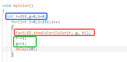
Three variables r, g, and b are defined in the function.
- Setting one of them to 255 means this color will be turned on first:
- If r = 255, the red light turns on; similarly, g = 255 turns on the green light, and b = 255 turns on the blue light.
- A for loop increments the variable i from 0 to 255 and modifies two of the variables in sequence to achieve color changes.
Upload program. (Please toggle the "Upload-Cam" button to "Upload"when uploading the program.) After the program has been upload successfully, please open the serial port and you will see the color of RG colored light is changing gradually.