¶ Introduction:
In this lesson, we will teach you how to make the car move as you wishby controlling the motor.
¶ Material Preparation:
- A Smart Robot Car (with battery)
- A USB Cable
First of all, let’s take a look at the 4 motors we used in our kit.
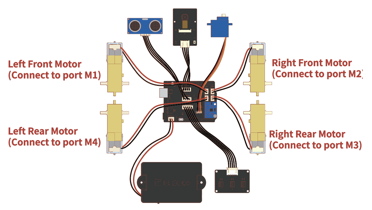
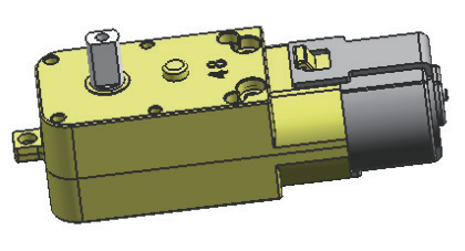
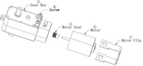
DC motor is the inductive load of large current (load with inductanceparameters), while the IO port of Arduino UNO single-chip microcomputerwe used has weak load capacity (output current capacity), and the drivingcapacity is not enough to supply enough current for the motor to rotate.
Therefore, we chose to use the motor driver chip DRV8835. (Although theremay be slight differences in the performance of different driver chips, theyare generally the same in usage.):
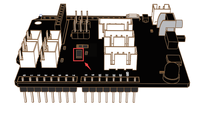
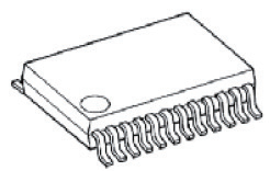
DRV8835 supplies enough current to the motor. Each H bridge of theDRV8835 can provide up to 1.5A of output current. It operates within themotor power voltage range of oV to 11V and the device power voltage rangeof 2Vto 7V.
DRV8835 acts as isolation to avoid damage of control devices by theimpulse current generated by the motor.
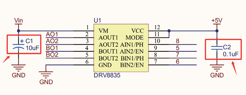
Perhaps everyone is more familiar with L298N. In fact, the use of the two isbasically the same. Compared with L298N's heat dissipation and peripheraldiode freewheeling circuit, it does not require an external heat sink, and theperipheral circuit is simple. It only needs an external power filter capacitor.Directly driving the motor is beneficial to reduce the size of the system, andthe frequency of up to 100KHZ is sufficient to meet most of our needs.
Please open the folder of last level for details: Related chip information ->DRV8835 and SmartCar-Shield-V1.0
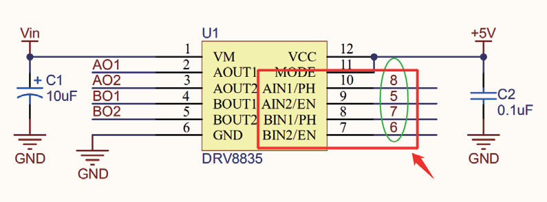
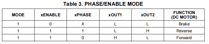
EN stands for enable pin, which changes the motor speed by changingPWM(0~255).
PH stands for phase pin, and the rotation direction (positive/reverse) of themotor is changed by changing the pin level (0/1).
In motor A, PWMA is connected to the UNO~D5 pins and AIN1 is connectedto the UNO D8 pin.
In motor B, PWMB is connected to the UNO~D6 pins and BIN1 is connectedto the UNO D7pin.
Finally, the driving method can be obtained from Related chipinformation->DRV8835
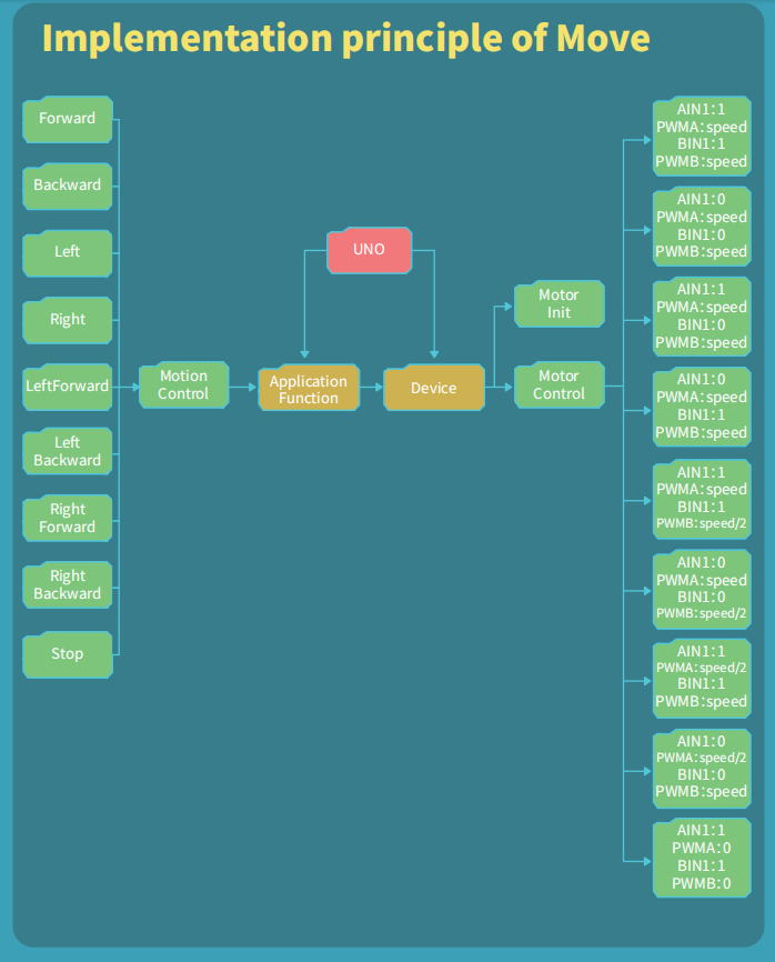
Then, we can start writing program according to the flow chart below.Please open Demo1 in the current folder:
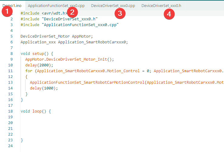
First of all, we can see that there are four files.
Next, let’s take a look at the definition of the relevant pins and variables:/ in DeviceDriverSet_xxx0.h
#ifndef DeviceDriverSet_xxx0_H
#define DeviceDriverSet_xxx0_H#include <arduino.h>
/Motor/
class DeviceDriverSet_Motor
{
public:
void DeviceDriverSet_Motor_Init(void);
#if _Test_DeviceDriverSet
void DeviceDriverSet_Motor_Test(void);
#endif
void DeviceDriverSet_Motor_control(boolean direction_A, uint8_t speed_A, //A组电机参数
boolean direction_B, uint8_t speed_B, //B组电机参数
boolean controlED //AB使能允许 true
); //电机控制
private:#define PIN_Motor_PWMA 5
#define PIN_Motor_PWMB 6
#define PIN_Motor_BIN_1 7
#define PIN_Motor_AIN_1 8public:
#define speed_Max 255
#define direction_just true
#define direction_back false
#define direction_void 3#define Duration_enable true
#define Duration_disable false
#define control_enable true
#define control_disable false
};#endif
Define the maximum speed of motor rotation:
#define speed_Max 255
Motor rotation direction flag
#define direction_just true
#define direction_back false
#define direction_void 3
These pins need to be initialized before they can be operated:in DeviceDriverSet_xxx0.cpp
void DeviceDriverSet_Motor::DeviceDriverSet_Motor_Init(void)
{
pinMode(PIN_Motor_PWMA, OUTPUT);
pinMode(PIN_Motor_PWMB, OUTPUT);
pinMode(PIN_Motor_AIN_1, OUTPUT);
pinMode(PIN_Motor_BIN_1, OUTPUT);
}
After initializing the pins, we can change the status of the pins to controlthe motor and make the motor rotate as we want.
- Car Motion://in ApplicationFunctionSet_xxx0.cpp
The motion control direction of the intelligent machine car is defined, including forward, backward, left turn, right turn and other directions.
enum SmartRobotCarMotionControl
{
Forward, //(1)
Backward, //(2)
Left, //(3)
Right, //(4)
LeftForward, //(5)
LeftBackward, //(6)
RightForward, //(7)
RightBackward, //(8)
stop_it //(9)
}; //direction方向:(1)、(2)、 (3)、(4)、(5)、(6)
- Motor control:// in DeviceDriverSet_xxx0.h
void DeviceDriverSet_Motor::DeviceDriverSet_Motor_control(boolean direction_A, uint8_t speed_A,
boolean direction_B, uint8_t speed_B, boolean controlED )
parameter:
direction_A、direction_B: Passing motor rotation direction flag.
speed_A,speed_B:range 0~255
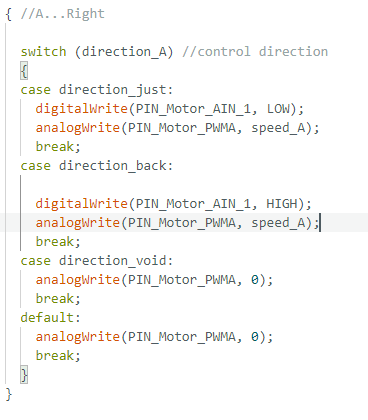
Based on
direction_A:
The program controls the right motor by judging the direction_A parameter:
when the parameter is direction_just, it sets the direction pin to LOW and outputs PWM speed to control the motor forward;
when it is direction_back, it sets HIGH to control backward; when it is direction_void or in default state, the PWM output is set to 0 to stop the motor.
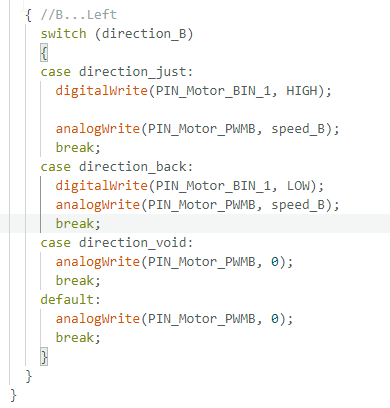
The program controls the left motor by judging the direction_B parameter, similar to A : when the parameter is
direction_just, set the direction pin to HIGH and output PWM speed to control the motor forward; when it isdirection_back, set the direction pin to LOW to control reverse; when it isdirection_voidor in the default state, set PWM output to 0 to stop the motor.
Next, let's look at the main motion control program of the small car:ApplicationFunctionSet_xxx0.cpp
It is very simple to control the robot car to achieve different motion states. Just pass in the corresponding motion direction and running speed parameters, and call the following function to realize it.
void ApplicationFunctionSet_SmartRobotCarMotionControl(SmartRobotCarMotionControl direction, uint8_t is_speed)
This function requires two parameters: movement direction and speed.
-
Input: You give a movement direction (like forward/left/backward) and a speed value.
-
Purpose: Controls the robot car to move in the specified direction at the set speed.
Switch Case Logic & Workflow
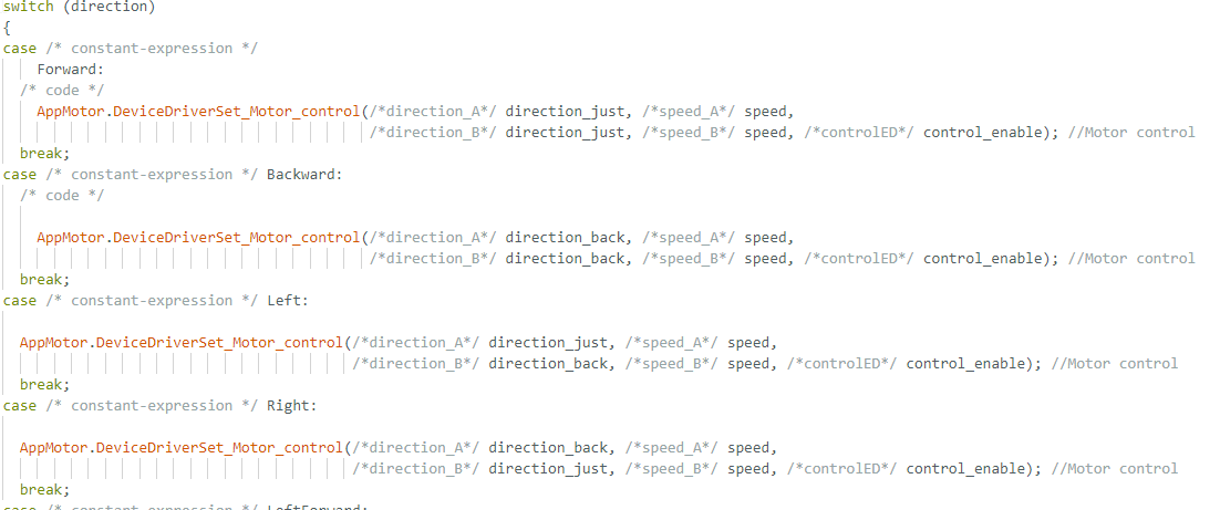
For each direction, it sets left motor and right motor (direction + speed) differently.
It calls the bottom motor driver to execute the action.
Brief Movement Logic:
Forward / Backward: Both motors run same direction at full speed.
Left / Right: Motors run opposite directions for in-place turning.
Diagonal directions (LeftForward, RightBackward...): One motor runs at half speed to make arc/diagonal movement.
Stop_it: Stops both motors immediately (speed = 0).
In the end, make the car move in each direction for one second after 2s waiting.
void setup() {
AppMotor.DeviceDriverSet_Motor_Init();
delay(2000);
for (Application_SmartRobotCarxxx0.Motion_Control = 0;
Application_SmartRobotCarxxx0.Motion_Control < 9;
Application_SmartRobotCarxxx0.Motion_Control = Application_SmartRobotCarxxx0.Motion_Control + 1)
{
ApplicationFunctionSet_SmartRobotCarMotionControl(Application_SmartRobotCarxxx0.Motion_Control /direction/, 200 /speed/);
delay(1000);
}
}
Upload the program.
(Pleasetoggle the "Upload-Cam" button to "Upload"when uploading the program.) Place the car on the ground and turn on theswitch after the program has been uploaded successfully.
Then, you will seethe car move forward, move backward, turn left, turn right, turn front-left,left-rear, turn front-right, turn right-rear at 1s intervals and finally stop.
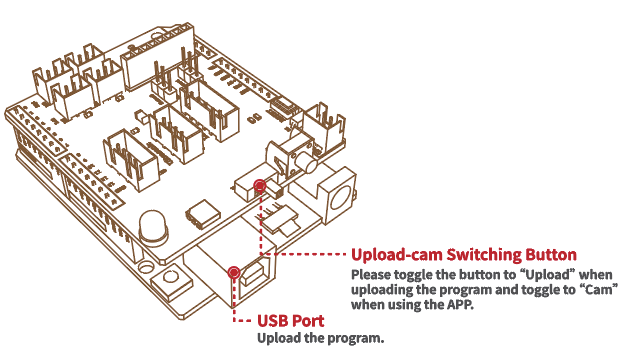
You can upload the program of Demo2 to keep observing if you don't see itclearly in the Demol.
Upload the program. (Please toggle the button B/U to "Upload" whenuploading the program.) You will see the car move forward and backwardat 1s of intervals. In the process of moving forward and backward, themoving route will have a more obvious deviation.
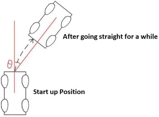
From the above, we know that similar to driving a car, if you close youreyes, it is difficult to keep walking straight for a long distance even if youstraighten the steering wheel. Therefore, we have to get the deviation by eyeand then correct it by turning the steering wheel manually to walk a straightline. Therefore, if we want the car to go in a straight line, we must introduceclosed-loop control.
Closed-loop control is a basic concept of cybernetics. Refers to a controlrelationship in which the controlled output returns to the controlled inputin a certain way and exerts a control influence on the input.
The advantage of closed-loop control over open-loop control is that it allowsthe results of the control to be fed back and compared to the desired valuesand adjusts the control effect based on theirerrors.
Therefore, by applying closed-loop control to Smart Robot Car, we canperform speed corrections via the PID algorithm after integrating the yawaxis data by obtaining the angular velocity filter of the deviation via theMPU6050.
Next, please open Demo3 in the current folder.
In this routine, we first ported the "MPU6050.h" library.

Let's first define a related class and class variable://in MPU6050_getdata.h
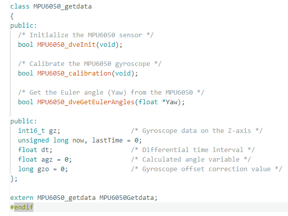
Defines the MPU6050 class
Declares 3 callable functions: Init, Calibration, Get Angle
Stores variables: gyro data, time, angle, offset
After declaring variables and functions in the header file, the specific implementation logic of these functions will be written in the MPU6050_getdata.cpp file. Therefore, you can also understand the functionality of the .cpp file starting from these three core functions.
MPU6050_dveInit(void)
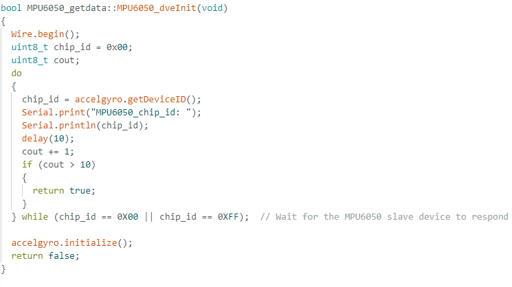
Function: Initialize the I2C bus and check if the MPU6050 sensor is connected and working properly.
Principle: Reads chip ID repeatedly. If the sensor responds normally, it initializes the sensor; if no response after 10 attempts, it returns an error.
MPU6050_calibration(void)
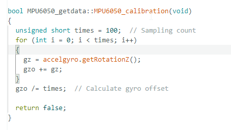
Function: Calibrate the Z-axis gyroscope to eliminate drift when the car is stationary.
Principle: Sample 100 times, calculate the average offset value, and store it in gzo to correct angle calculation.
MPU6050_dveGetEulerAngles()
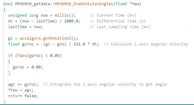
angular velocity along the Z-axis = (gyro z-axis raw data /131) °/s.
Because the execution time of the program is less than 1S, we need to multiply the final result by time.
Finally, the yaw value can be obtained by integrating the resulting angular velocity.
Functions and variables are declared in the .h header file, and the actual function logic is implemented in the .cpp file.
To make the MPU6050 work properly, you must call these functions in the main program.You can refer to the Demo3.ino example file for the specific usage.
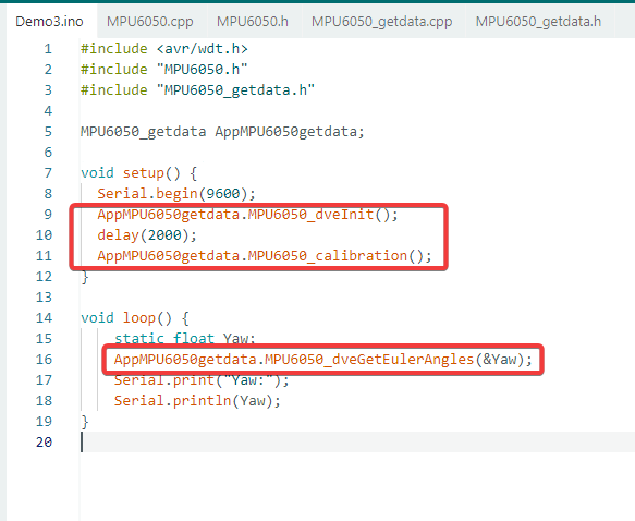
After powering on, the MPU6050 requires initialization and a calibration function to obtain the current angle offset.Therefore, MPU6050_dveInit() and MPU6050_calibration() must be placed in the setup() function and run only once.
Since the angle data from the MPU6050 changes continuously while the car is moving,
MPU6050_dveGetEulerAngles(&Yaw) needs to be placed inside the loop() function to read the latest data in real time.
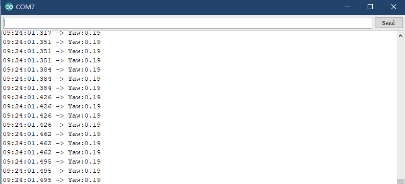
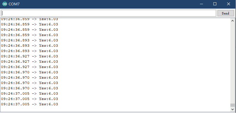
Please place the car steadily before uploading the program. (Please togglethe "Upload-Cam" button to "Upload" when uploading the program.) Afteruploading the program, if you do not move the car, wait two seconds andopen the serial port, the yaw angle will fluctuate around 0. If you move thecar slightly, the yaw angle will also change accordingly. The straight-linewalking function of the car is programmed based on this principle.
<img src="/robots-kits/movement_25.png"alt="/robots-kits/movement_25.png"
style="max-width: 100%; height: auto; border-radius: 4px; margin: 10px auto; display: block;">
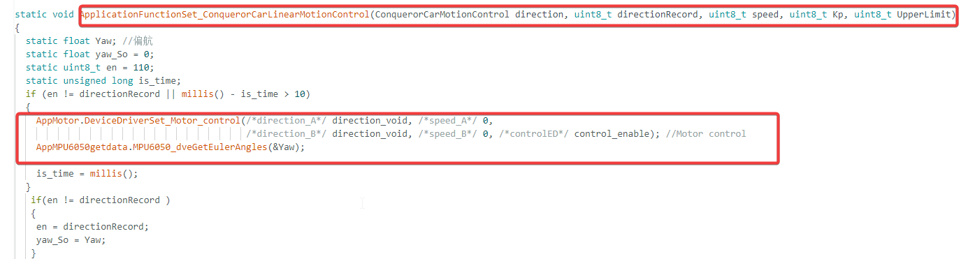
After the yaw data is obtained, the closed-loop feedback control can beachieved through PID algorithm to adjust the wheel speed so as to achievestraight-line walking. Next, please open Demo4 in the current folder.
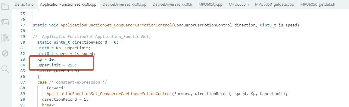
KP scale parameter is the best data we can get through repeated debugging.
UpperLimit is the maximum speed of the car.//in ApplicationFunctionSet_xxx0.cpp
The yaw data is acquired at the first startup, and the data is updatedevery ten millimeters.