¶ Tools and Materials
- 2.5mm Allen key x 1
- 2.0mm Allen key x 1
- New Z-axis shaft x 3
¶ Tutorial Video
Coming soon.
¶ Instruction
¶ Preparation
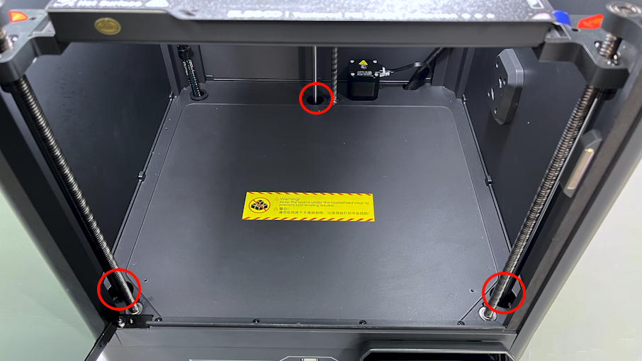
Check to ensure that there is no foreign matter inside the bearing holes before operation.
- Plug in the power cord and power on the printer.
- Select Function - all on the touchscreen and the printer starts the homing process.
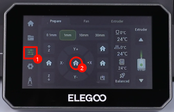
- On the touchscreen, select 30mm - lower down the Z-axis. The Z-axis lowers down to the bottom.
- Power off the printer and unplug the power cord.
¶ Remove the accessories, left-side, right-side and rear-side covers
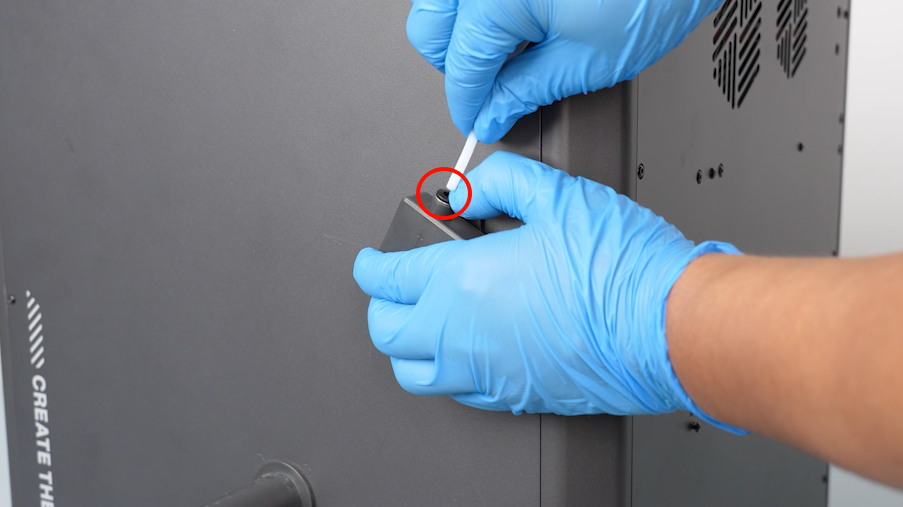
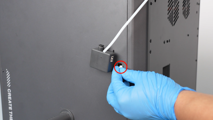
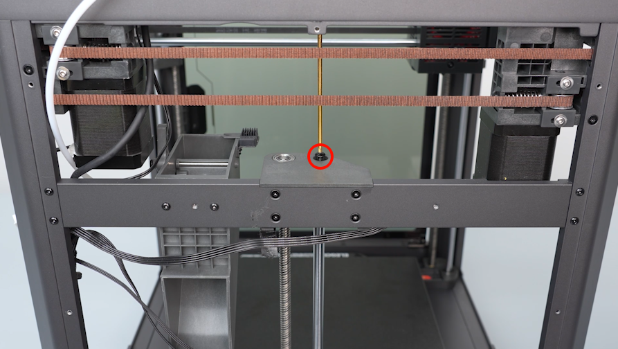
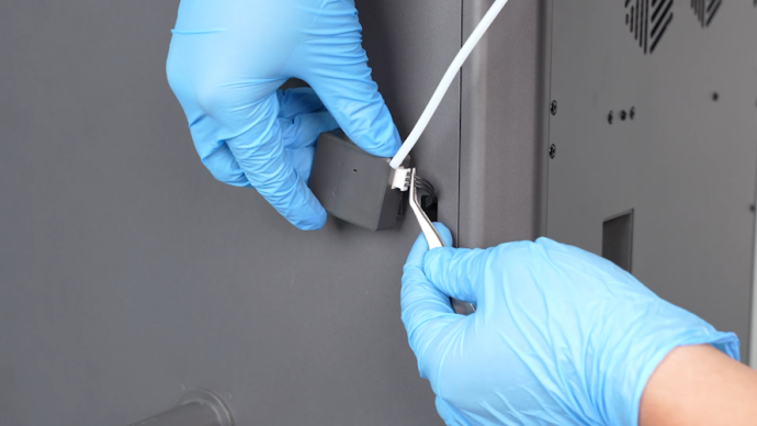
- Unplug the PTFE tube above the filament runout detetcion switch.
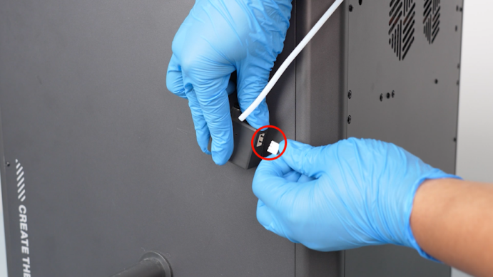
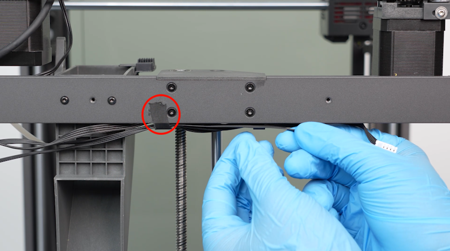
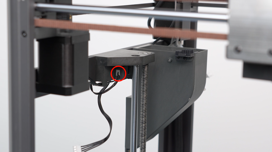
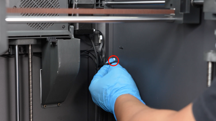
- Unplug the cables of the filament runout detection port. Pass thecables inside the printer through the cable hole.
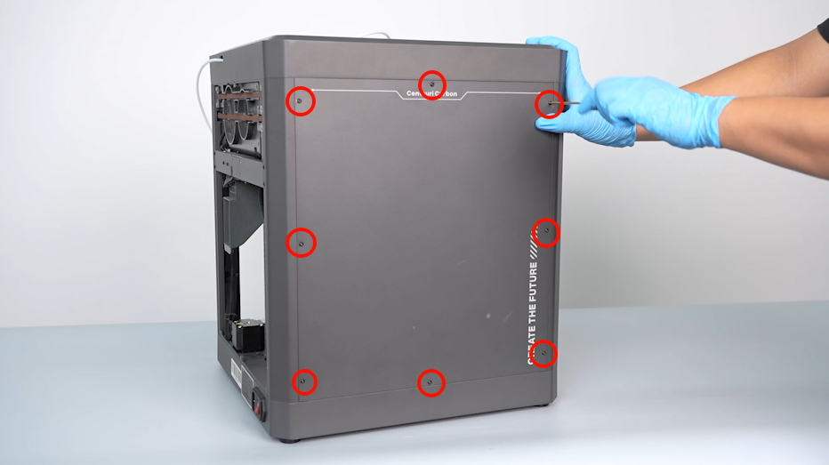
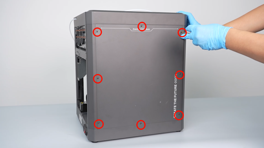
- Using a 2.0mm Allen key, loosen the eight screws holding the right-side cover. Remove the cover.
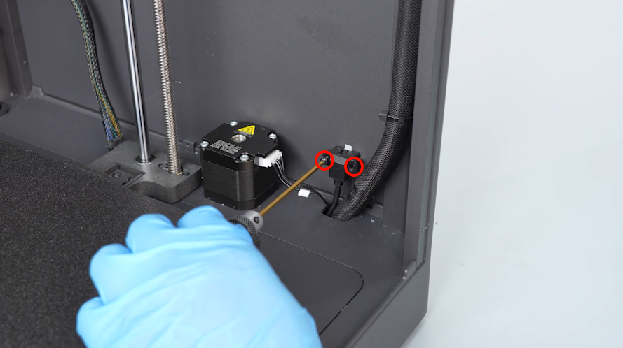
- Using a 2.0mm Allen key, loosen the two screws securing the multi-color connector. Remove connector.
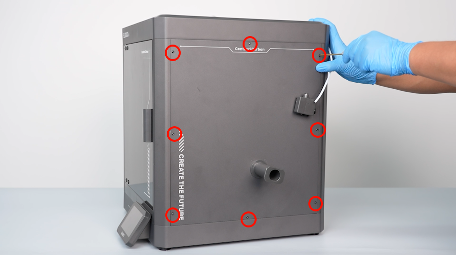
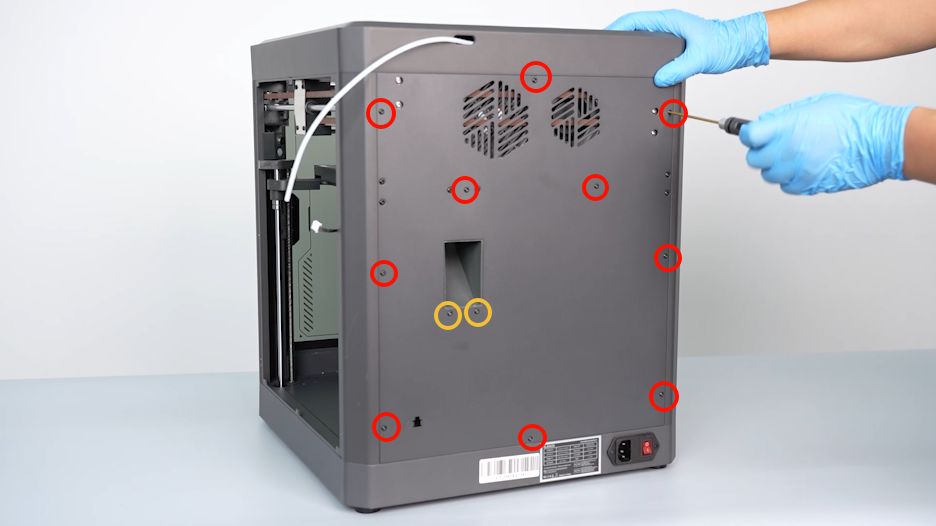
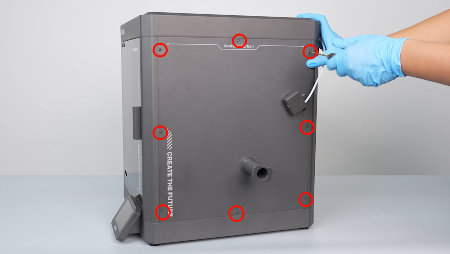
- Using a 2.0mm Allen key, loosen the twelve screws securing the back cover of the printer. Remove the back cover.
NOTE: Screw holes labeled by the red circle are M3*4, while screw holes labeled by the yellow circle are M3*8.

- Using a 2.0 mm Allen key, loosen the eight screws holding the left-side cover. Remove the cover.
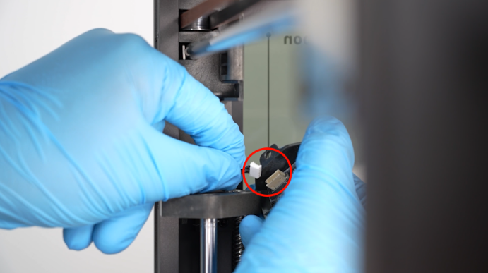
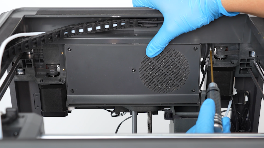
- Using a 2.0mm Allen key, loosen the screw securing the camera. Unplug the cables of the camera and remove the camera.
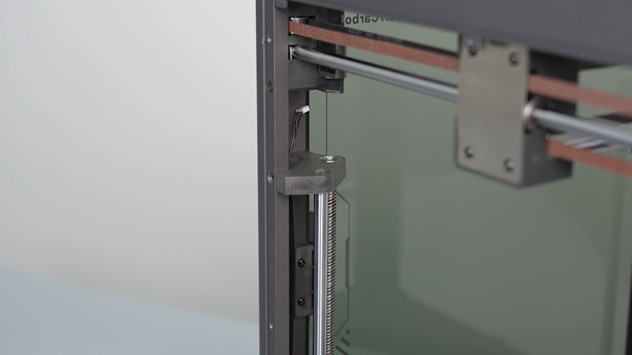
¶ Remove the old right-side shaft
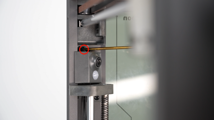
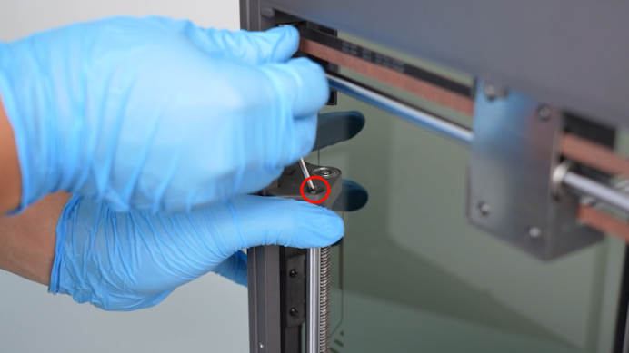
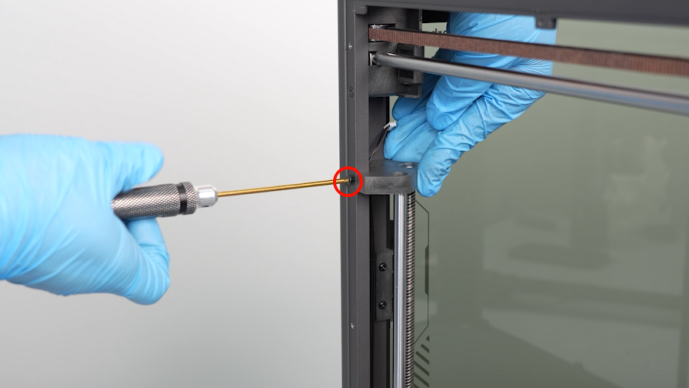
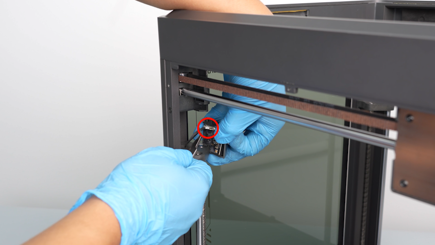
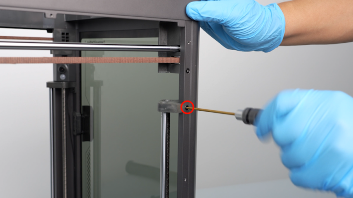
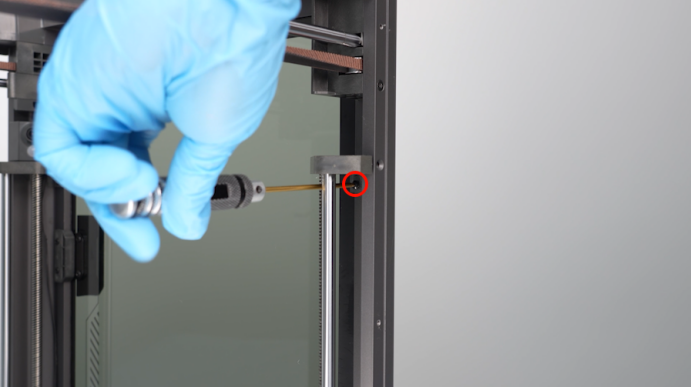
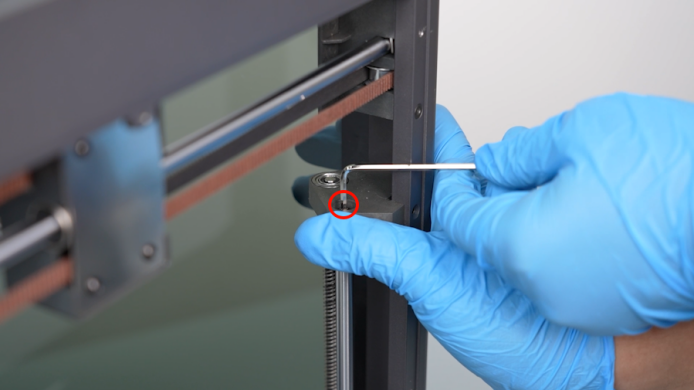
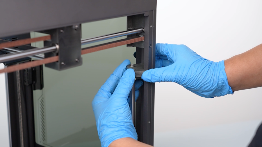
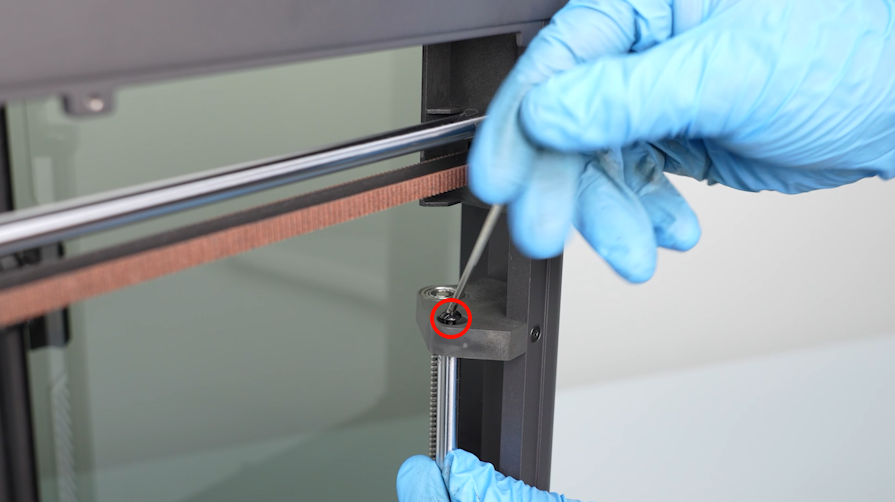
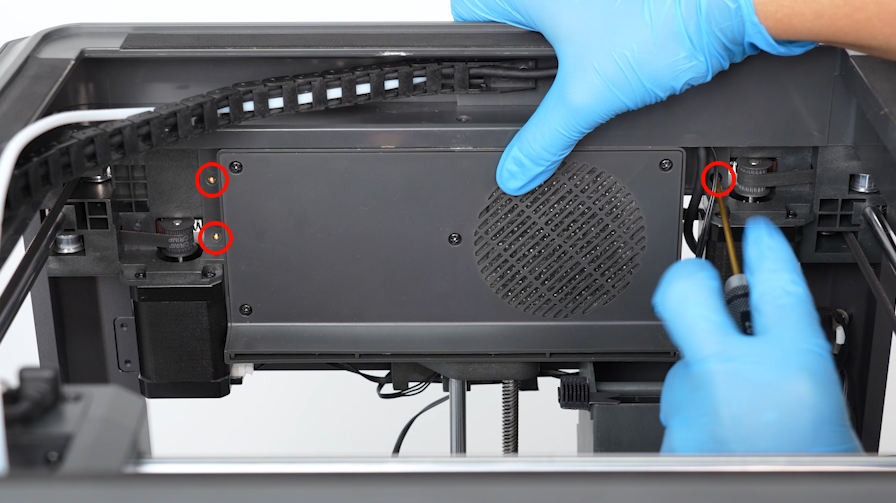
- Using a 2.0mm Allen key, remove the two screws securing the fixing block at the top of the Z-axis.
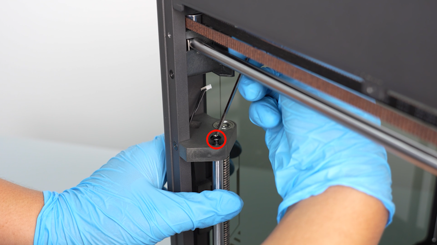
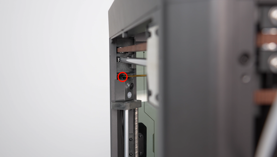
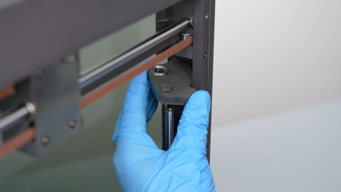
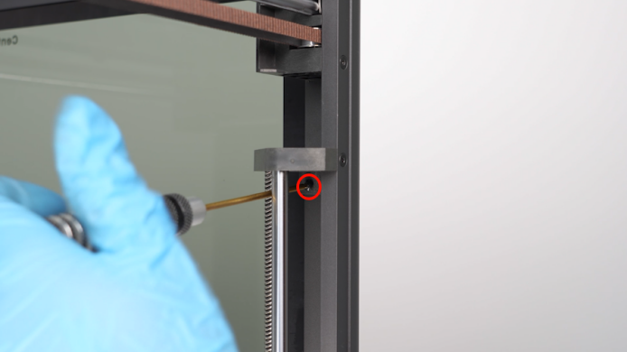
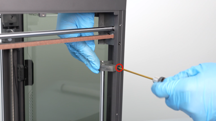
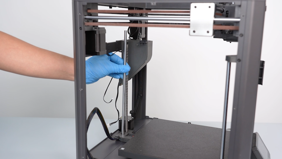
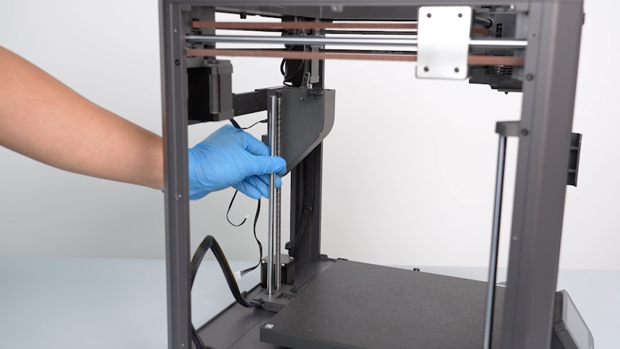
- Using a 2.5mm Allen key, remove the screw secured at the top of the shaft. Remove the fixing block at the at the top of Z-axis.
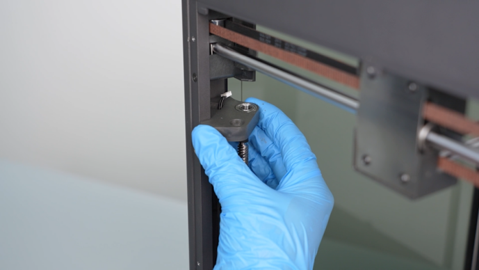
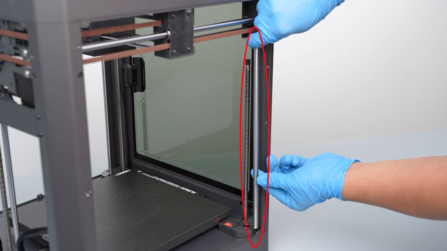
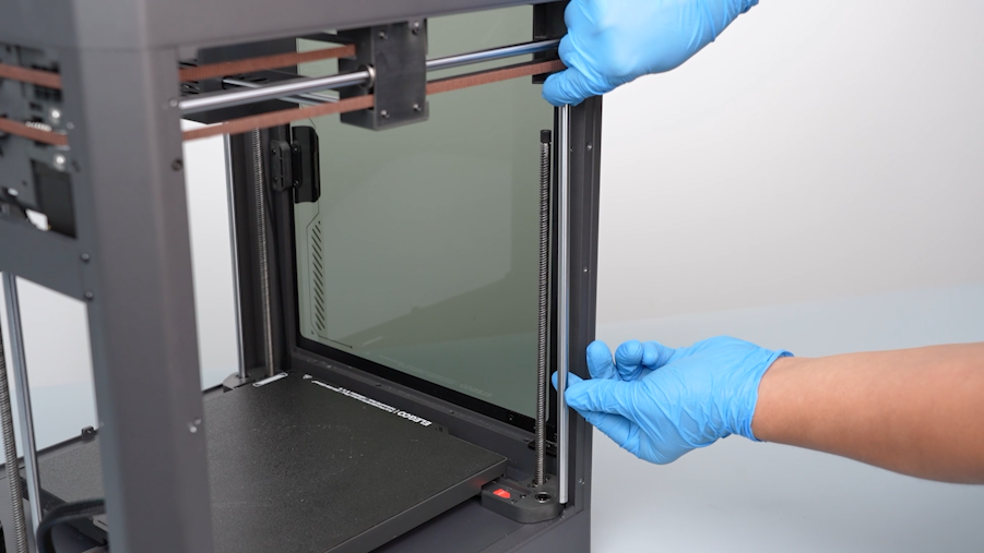
- Remove the old shaft.
¶ Install the new right-side shaft
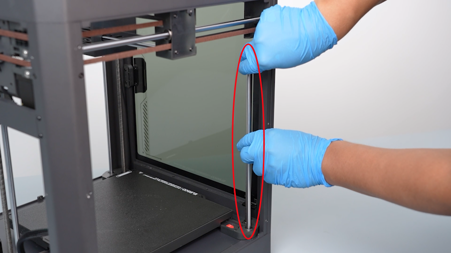
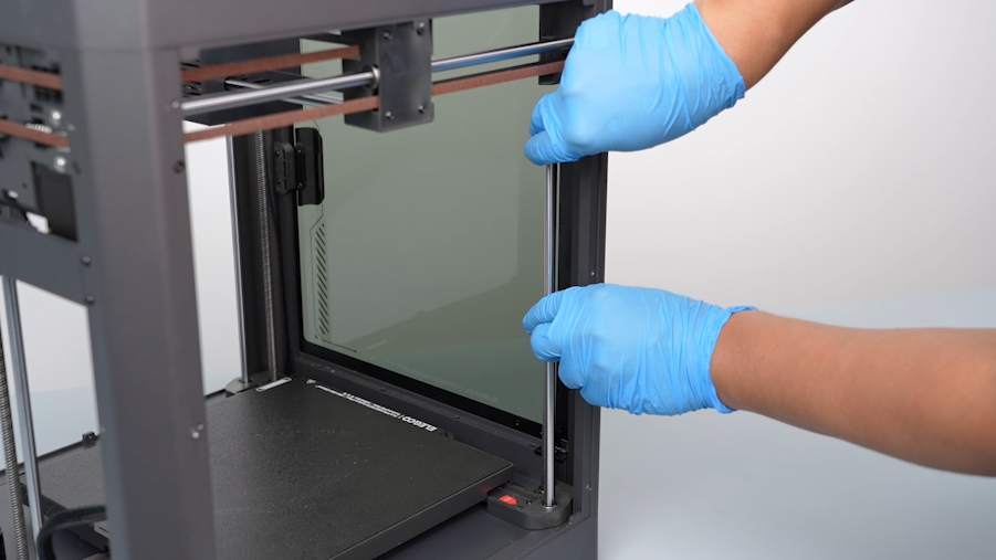
- Prepare the new bearing. Align the bearing with the installation holes and put it in the installation position.
- Align the fixing block at the top of the Z-axis with the lead screw and shaft hole. Put it in the installation position.
- Using a 2.0mm Allen key, tighten the two screws securing the fixing block at the top of the Z-axis.
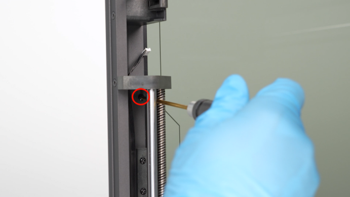
- Using a 2.5mm Allen key, tighten the screw secured at the top of the shaft.
- Prepare the camera. Insert the cables of the camera.
- Using a 2.0mm Allen key, tighten the screw securing the camera.
¶ Remove the old left-side shaft
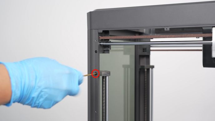
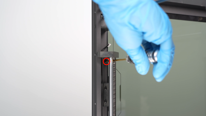
- Using a 2.0mm Allen key, remove the two screws securing the fixing block at the top of the Z-axis.
- Using a 2.5mm Allen key, remove the screw secured at the top of the shaft. Remove the fixing block at the at the top of Z-axis.
- Remove the old shaft.
¶ Install the new left-side shaft
- Prepare the new bearing. Align the bearing with the installation holes and put it in the installation position.
- Align the fixing block at the top of the Z-axis with the lead screw and shaft hole. Put it in the installation position.
- Using a 2.0mm Allen key, tighten the two screws securing the fixing block at the top of the Z-axis.
- Using a 2.5mm Allen key, tighten the screw secured at the top of the shaft.
¶ Remove the old rear-side shaft
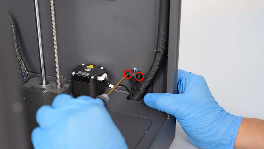
- Unplug the cables of the rear cooling fan assembly.
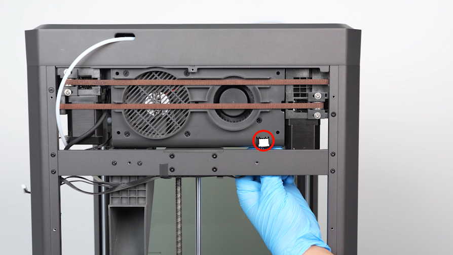
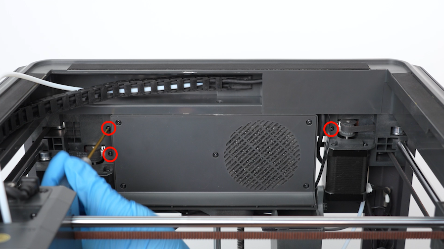
- Using a 2.0mm Allen key, loosen the three screws securing the rear-side cooling fan assembly . Remove the rear-side cooling fan assembly.
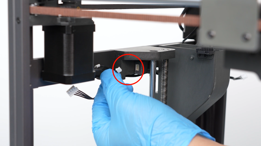
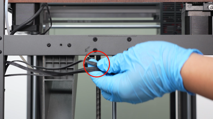
- Unplug the cables of the Z-axis limit switch.
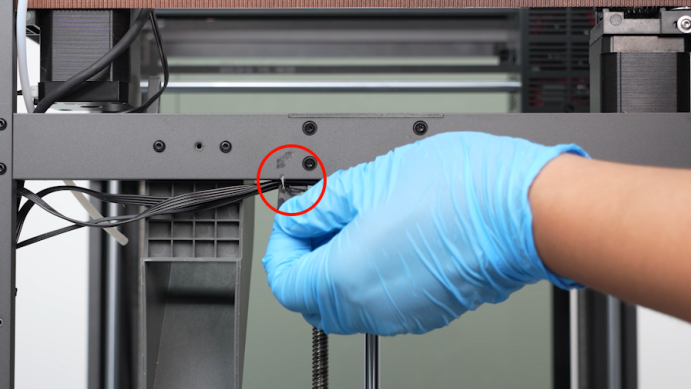
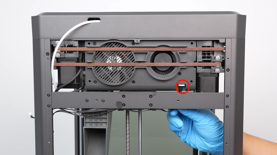
- Peel off the black tape securing the cables and remove the cables from the clip.
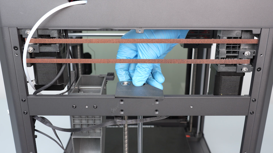
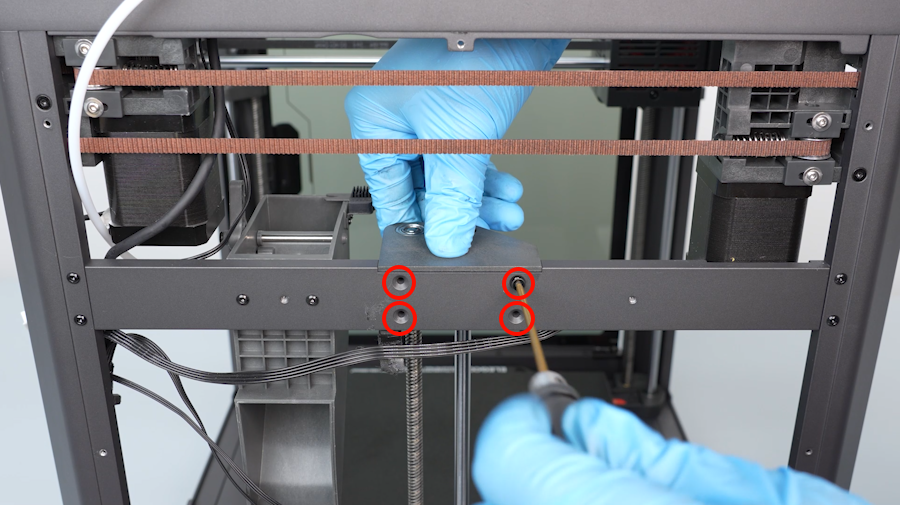
- Using a 2.0 mm Allen key, loosen the four screws securing the fixing block at the top of the Z-axis.
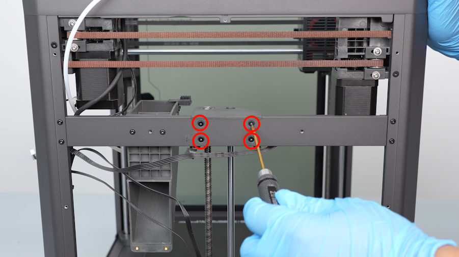
- Using a 2.5mm Allen key, loosen the screw secured at the top of the shaft.
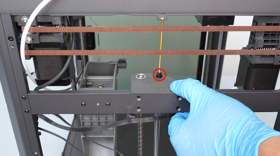
- Remove the fixing block at the top of the Z-axis.
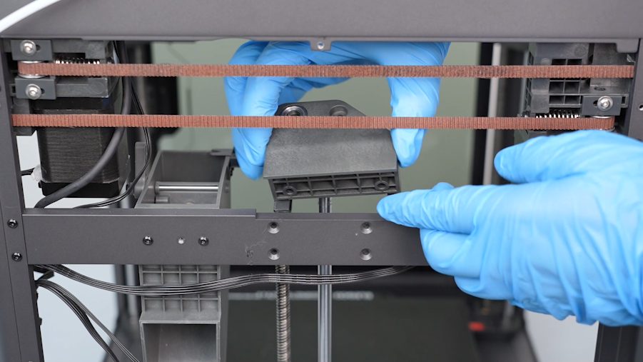
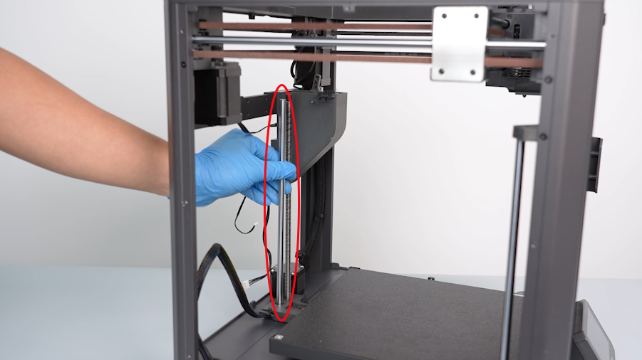
- Remove the old shaft.
¶ Install the new rear-side shaft
- Prepare the new shaft. Put it in the installation position.
- Align the fixing block at the top of the Z-axis with the lead screw and shaft hole. Put it in the installation position.
- Using a 2.0mm Allen key, tighten the four screws securing the fixing block at the top of the Z-axis.
- Using a 2.5mm Allen key, tighten the screw secured at the top of the shaft.
- Organize the cables and put them in the clip. Stick the black tape securing the cables.
- Insert the cables of the Z-axis limit switch port.
- Align the rear cooling fan assembly with the screw holes and put it in the installation position.
- Using a 2.0mm Allen key, tighten the three screws securing the rear cooling fan assembly.
- Insert the cables of the rear cooling fan assembly into the port.
¶ Install the accessories, left-side, right-side and rear-side covers
- Put the left-side cover in the installation position by aligning it with the screw holes. Using a 2.0mm Allen key, tighten the eight screws securing the left-side cover .
- Align the back cover with the screw holes and put it in the installation position. Using a 2.0mm Allen key, tighten the twelve screws securing the back cover .
- Align the the multi-color connector with the screw holes and put it in the installation position. Using a 2.0mm Allen key, tighten the two screws securing the multi-color connector.
- Put the right-side cover in the installation position by aligning it with the screw holes. Using a 2.0 mm Allen key, tighten the eight screws securing the right-side cover.
- Pass the cables of the filament runout detection through the hole. Insert the cables into the port of the filament runout detection.
- Insert the PTFF tube into the connector above the filament runout detection.
¶ Restart the printer
- Plug in the power cord and power on the printer.
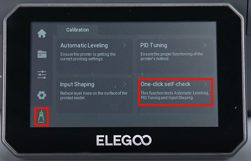
- Select Function - Self check - All - Start on the touchscreen.
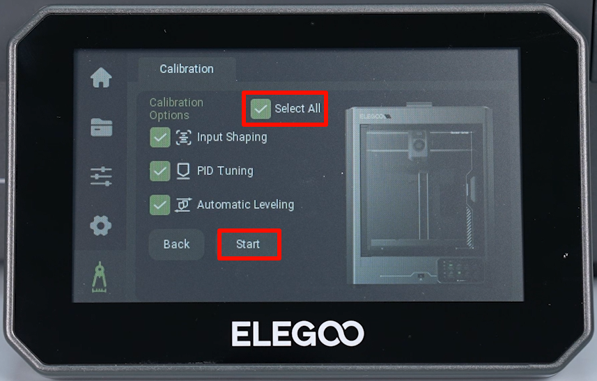
- The printer is ready for use after self inspection.