¶ Tools and Materials
- 2.5mm Allen key x 1
- 2.0mm Allen key x 1
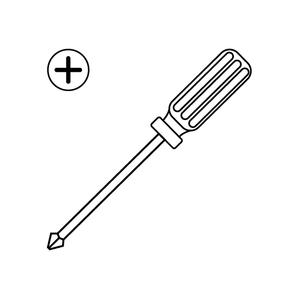
- A Phillips screwdriver
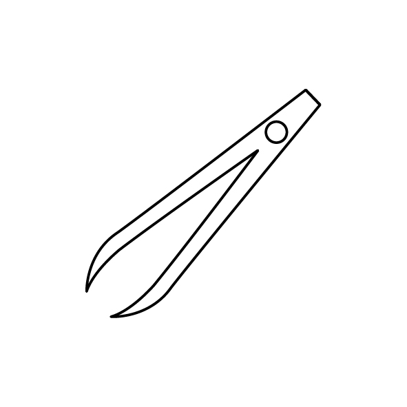
- A pair of tweezers
- New Z-axis lead screw x 3

¶ Tutorial Video
Coming soon.
¶ Instruction
- Power off the printer and unplug the power cord.
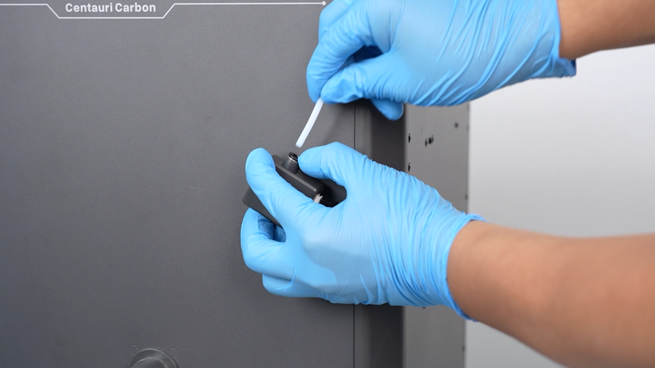
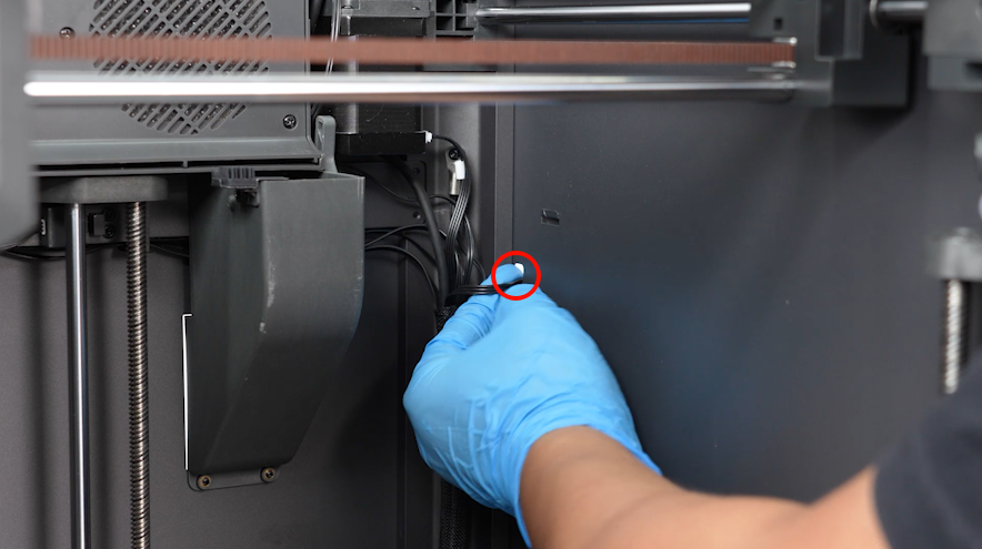
- Unplug the PTFE tube above the filament runout detetcion switch.
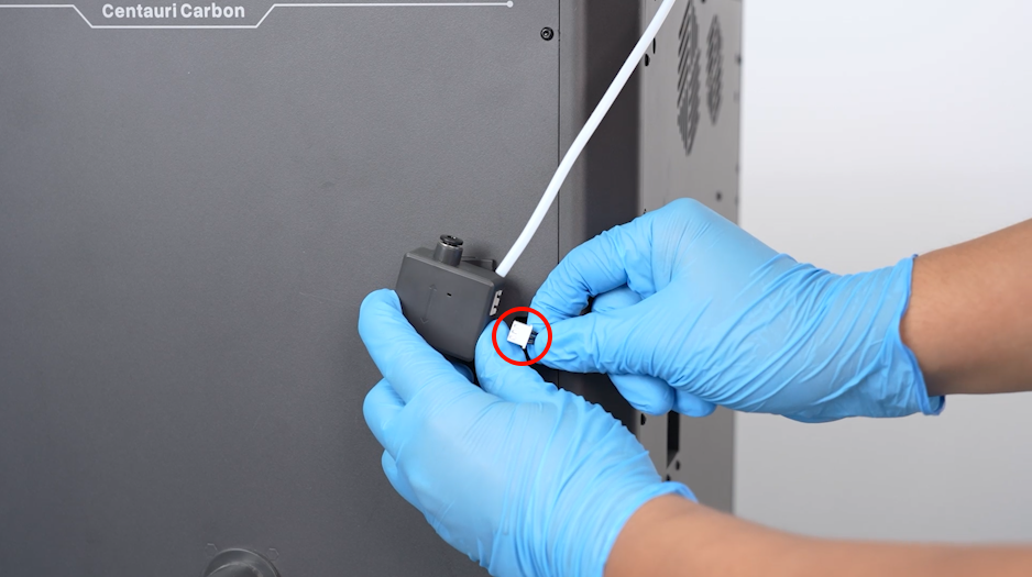
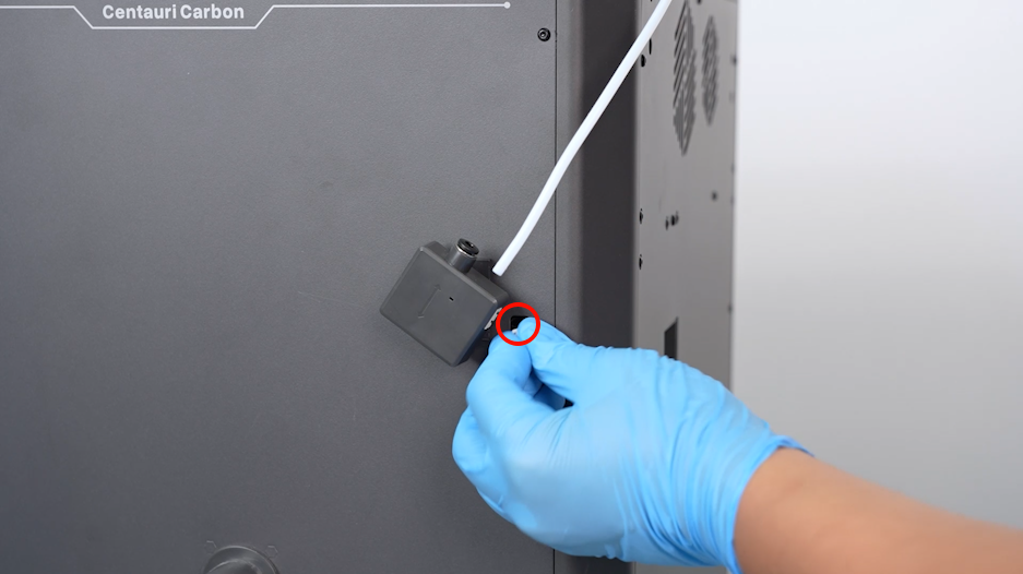
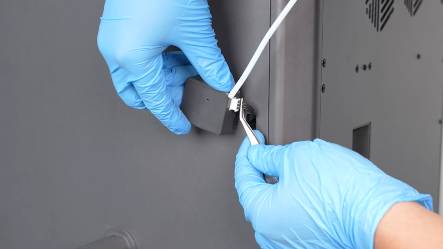
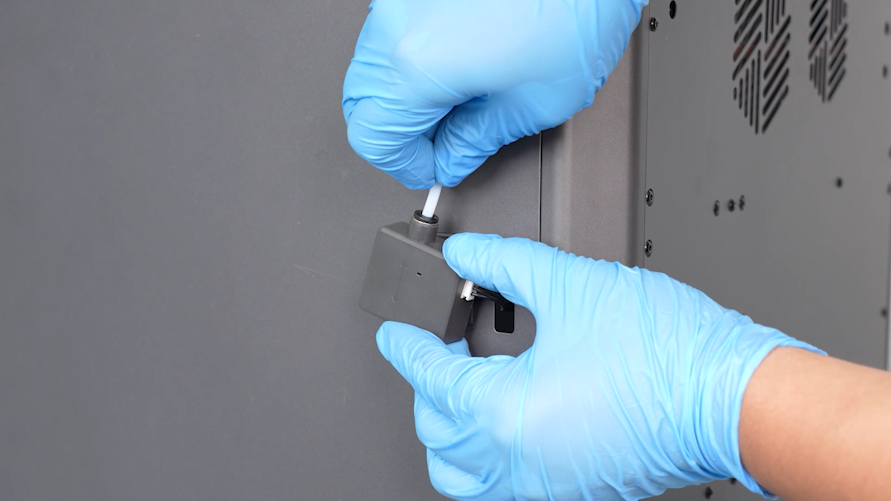
- Unplug the cables of the filament runout detection port. Pass thecables inside the printer through the cable hole.
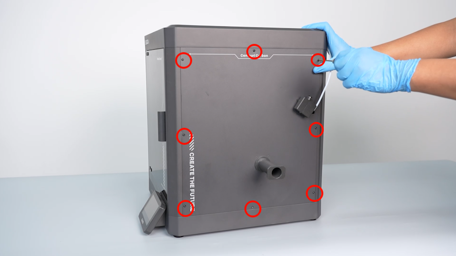
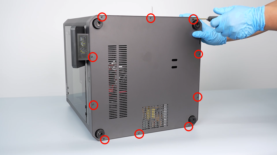
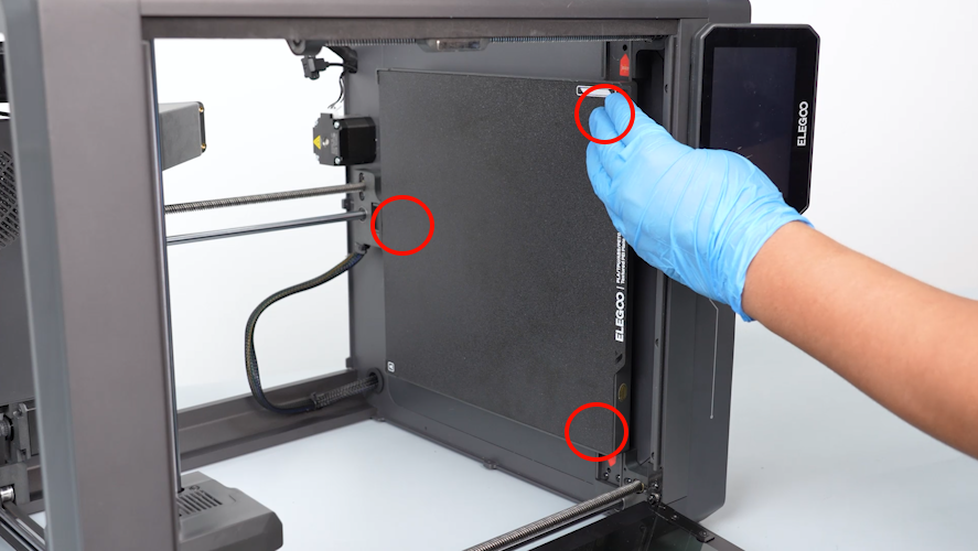
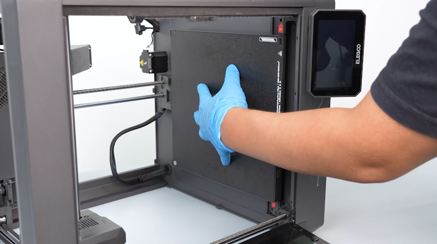
- Loosen the eight screws holding the right-side cover using a 2.0mm Allen key. Remove the cover.
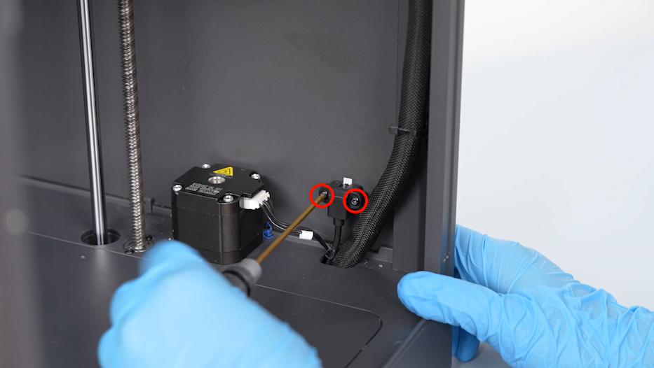
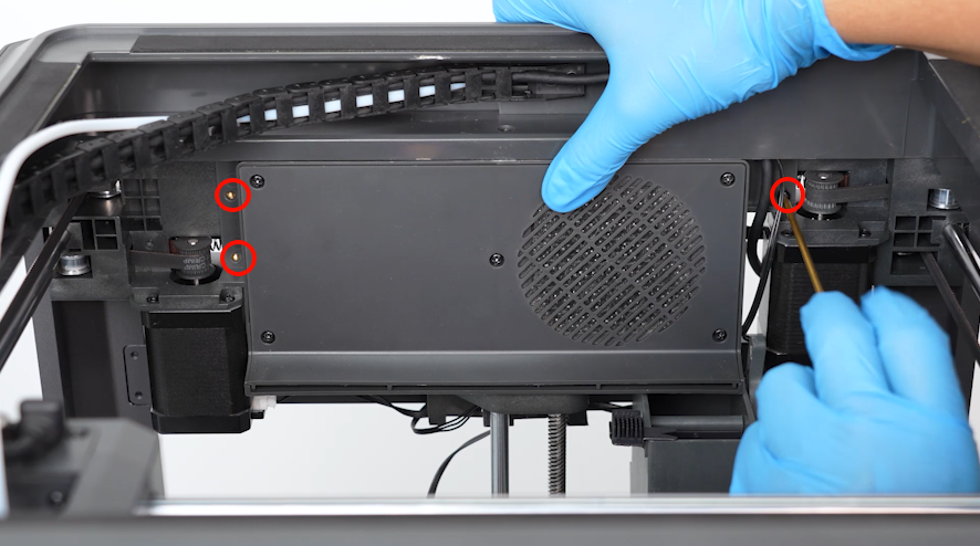
- Loosen the two screws securing the multi-color connector using a 2.0mm Allen key. Remove connector.
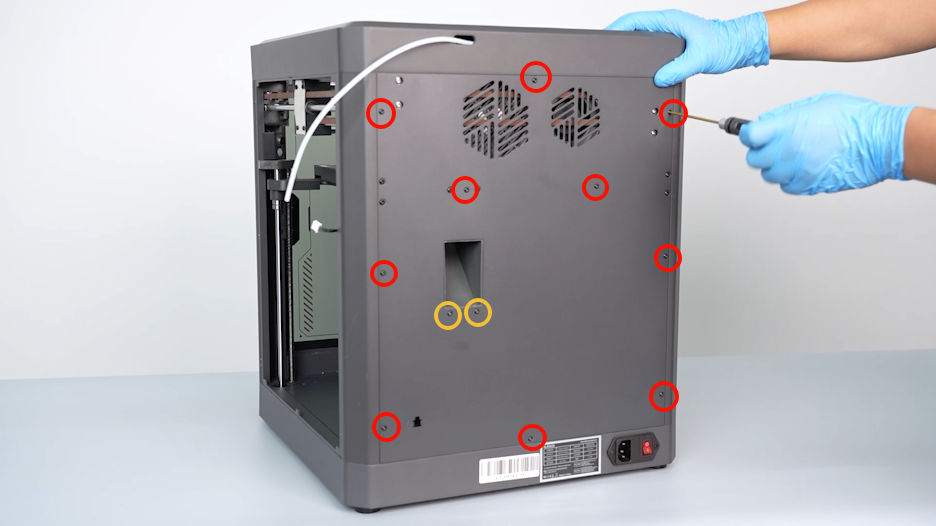
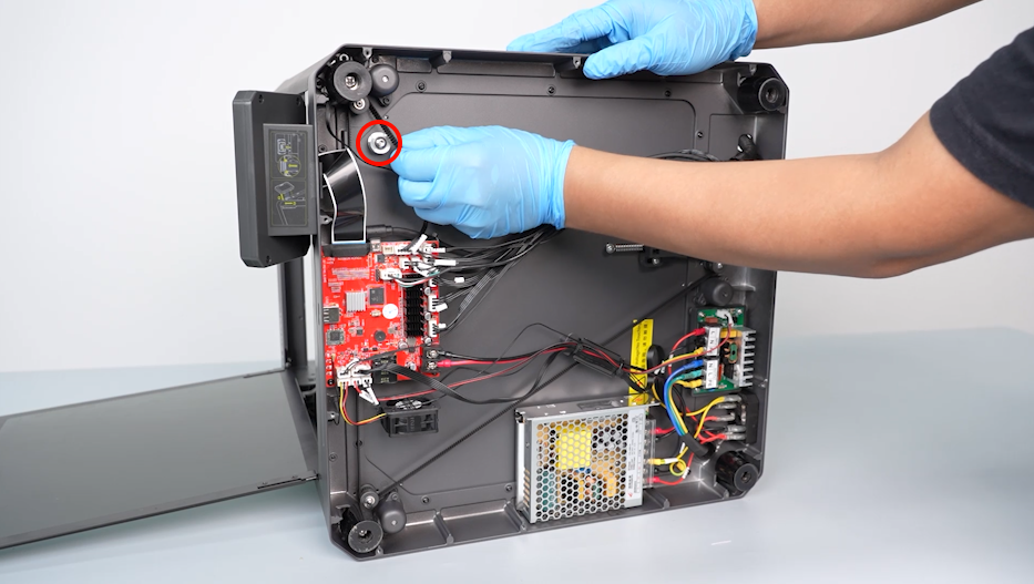
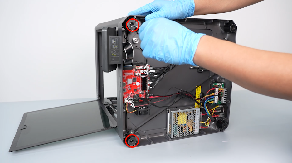
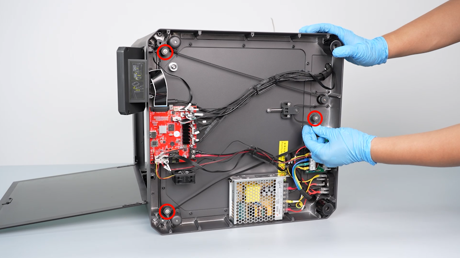
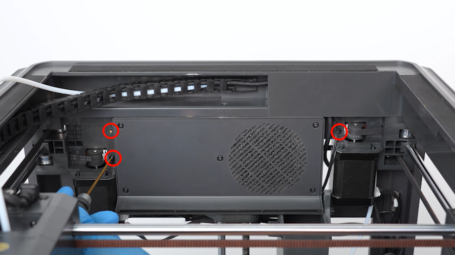
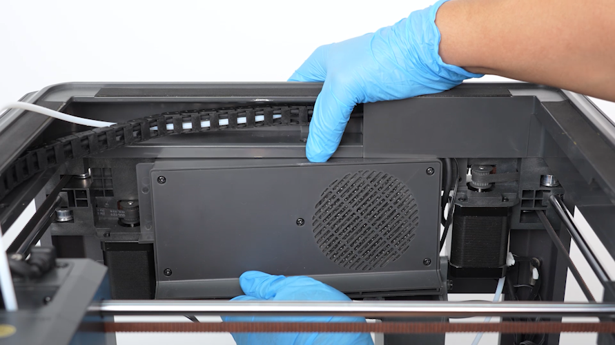
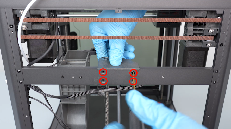
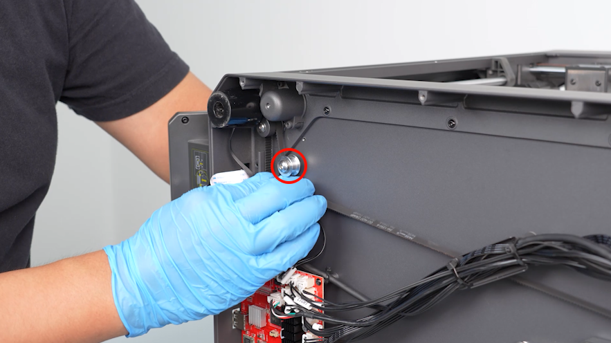
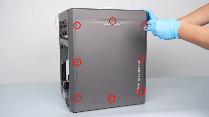
- Loosen the twelve screws securing the back cover of the printer using a 2.0mm Allen key. Remove the back cover.
NOTE: Screw holes labeled by the red circle are M3*4, while screw holes labeled by the yellow circle are M3*8.
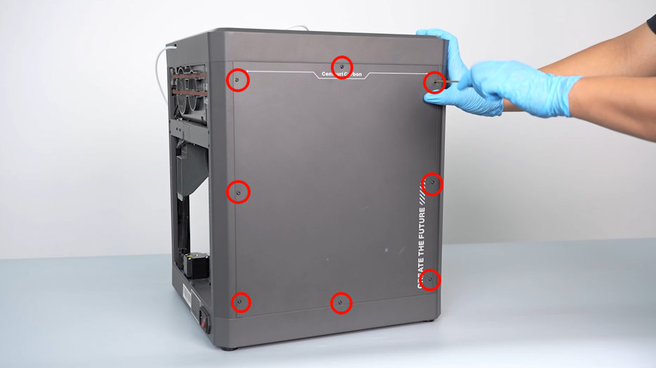
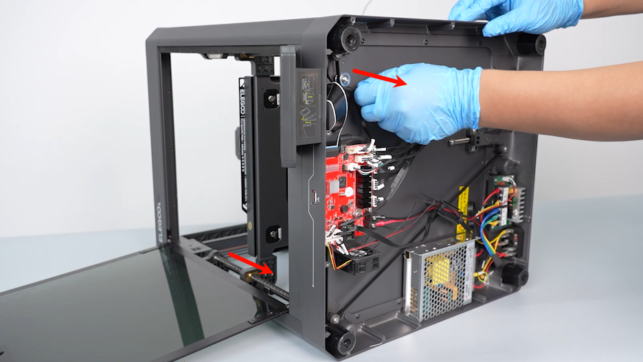
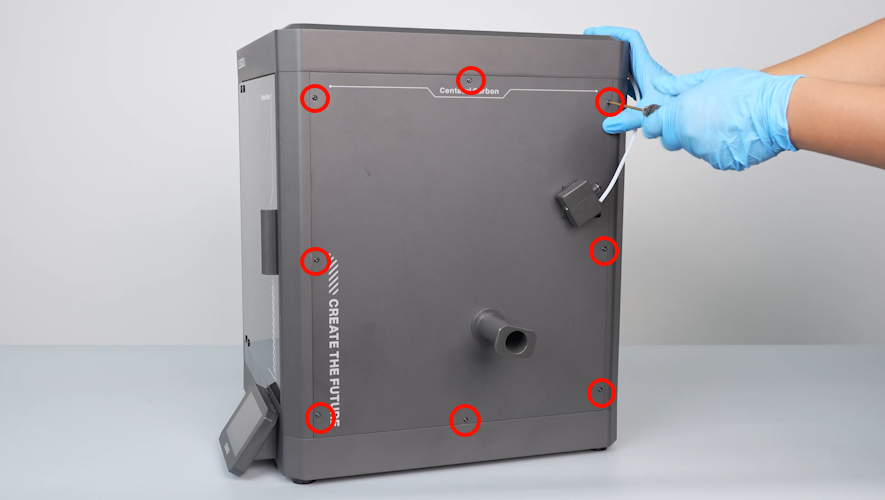
- Loosen the eight screws holding the left-side cover using a 2.0mm Allen key. Remove the cover.
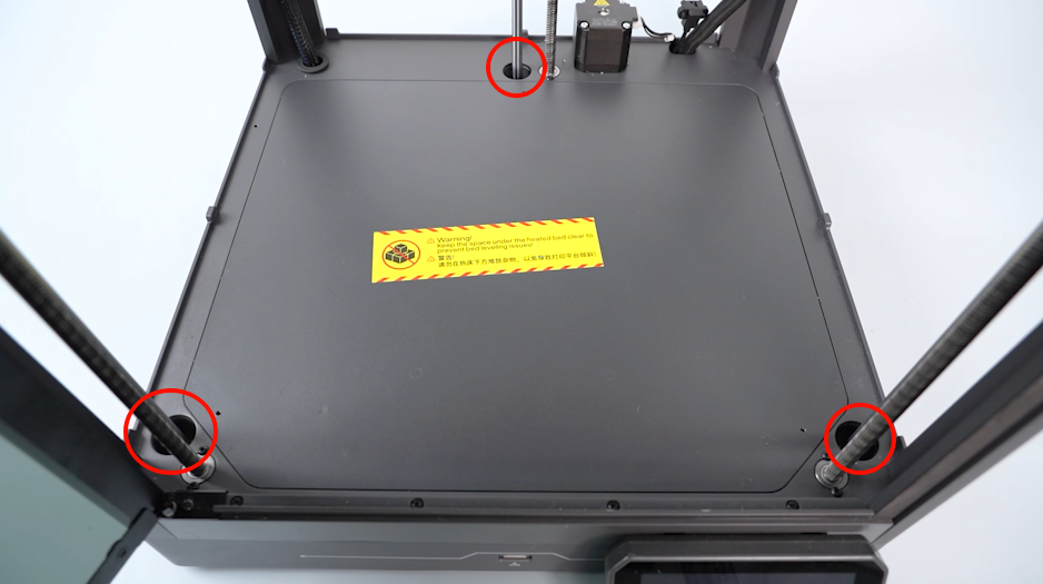
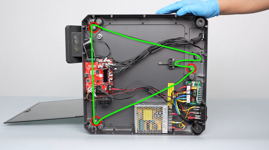
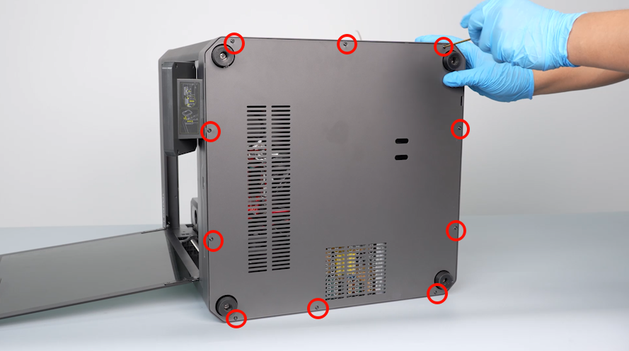
- Put the printer on its side. Loosen the twn screws securing the bottom cover of the printer using a 2.0mm Allen key. Remove the printer.
- Check to ensure that there is no foreign matter inside the bearing holes.
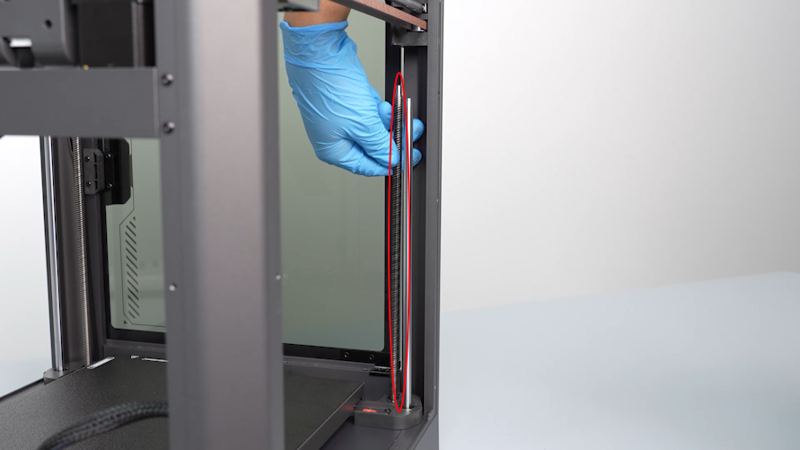
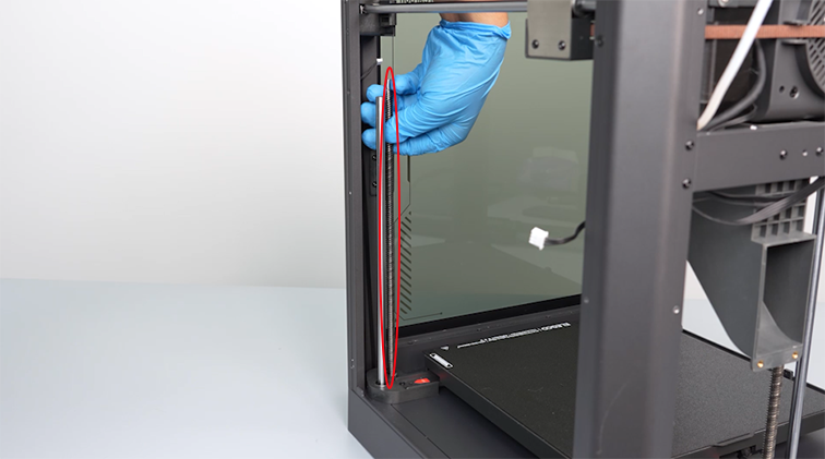
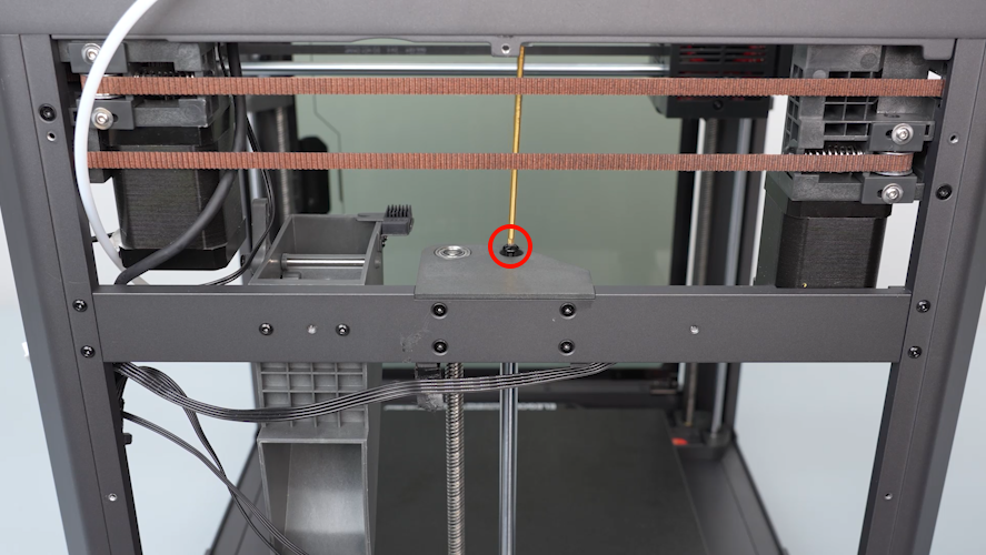
- Pull the timing belt to lower the heated bed to the bottom of the printer.
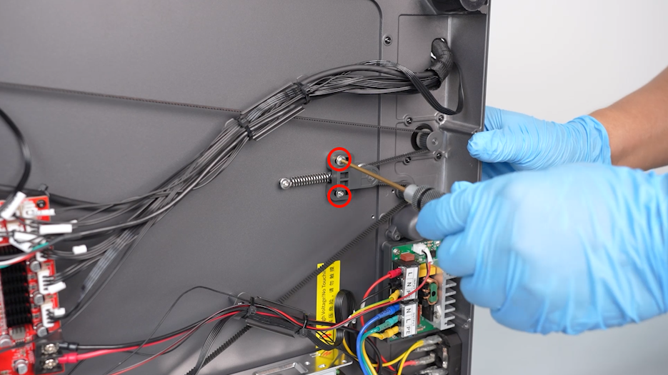
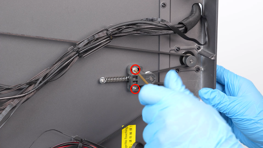
- Loosen the two screws securing the belt tensioner using a 2.0mm Allen key.
- Remove the timing belt from the idler pulley.
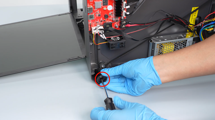
- Using a Phillips screwdriver, loosen the two foot pads at the twos sides of the motherboard.
- Remove the timing belt from the three timing pulleys.
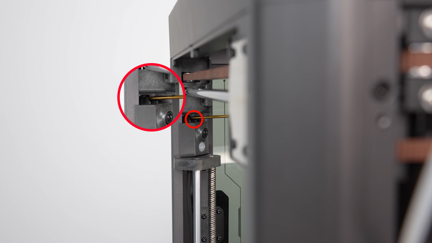
- Insert a 2.0mm Allen key into the side screw hole to secure the timing pulley. Using another 2.0mm Allen key, loosen the screw at the bottom of the timing pulley.
- Loosen the two screws securing the timing pulley using a 2.0mm Allen key. Remove the timing pulley.
- Remove the other two timing pulleys in the same way.
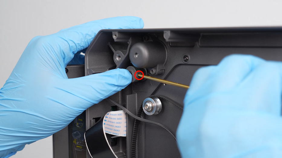
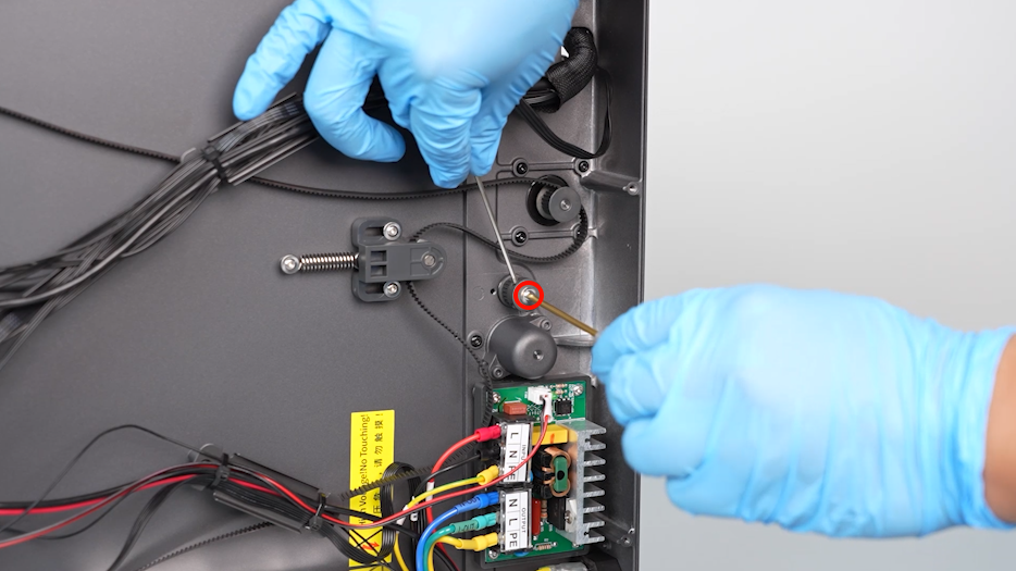
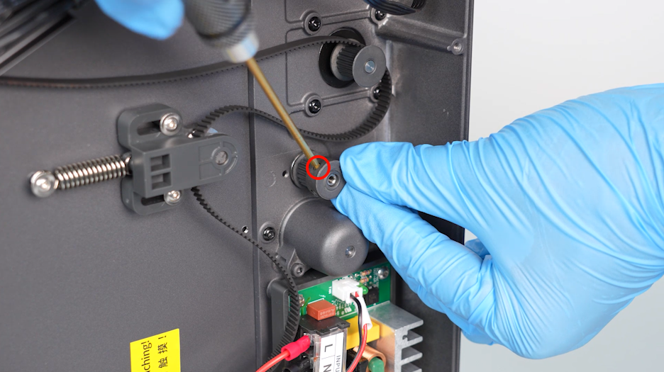
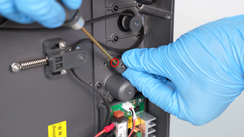
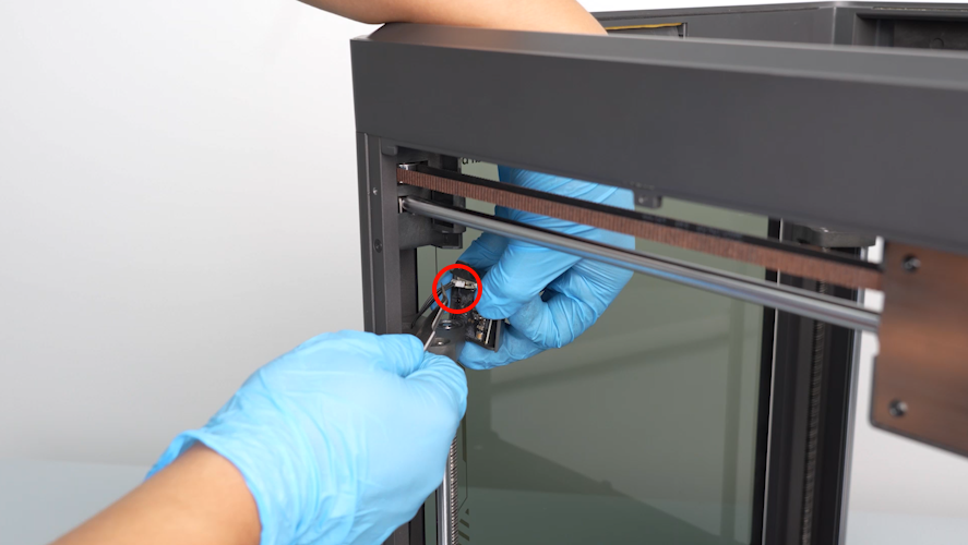
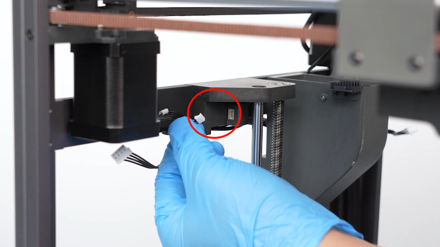
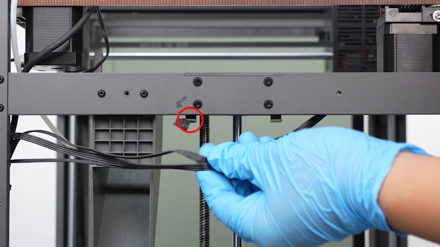
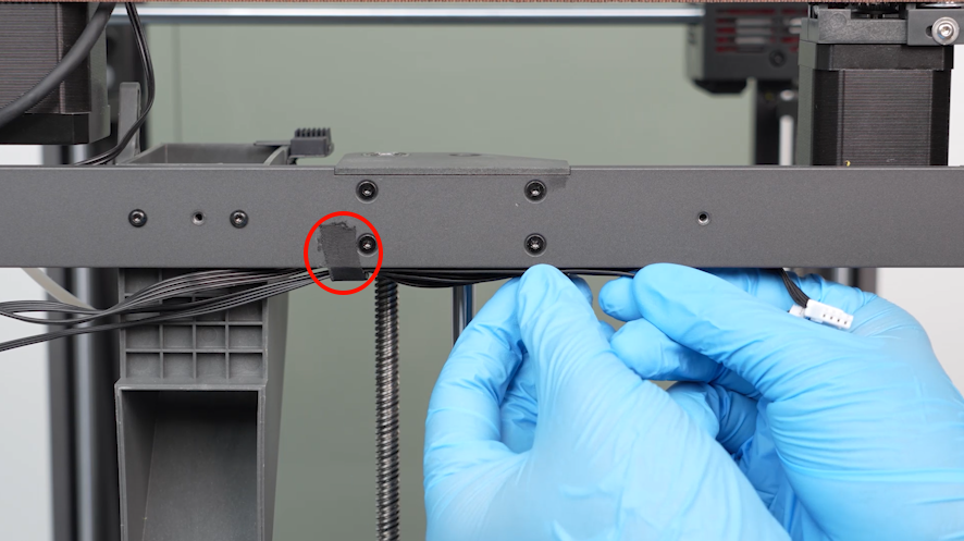
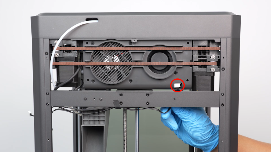
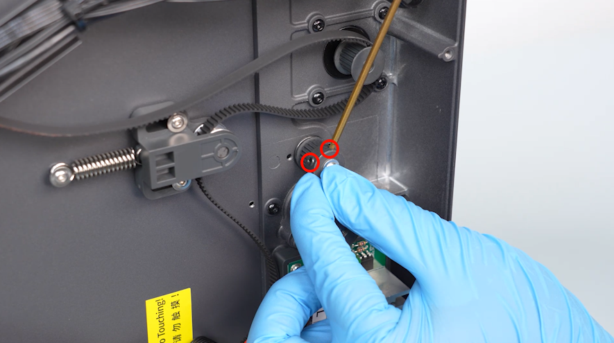
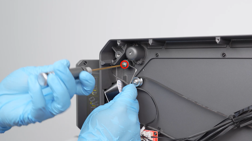
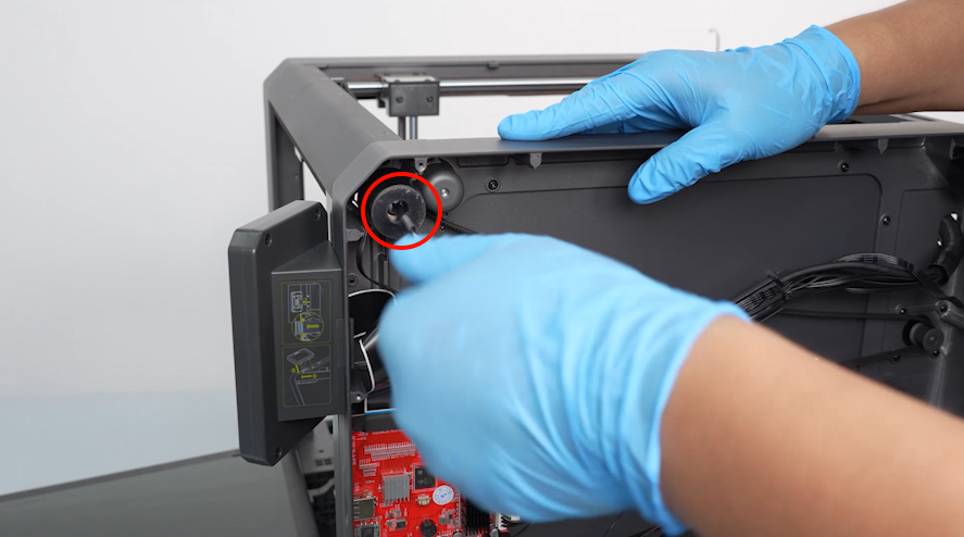
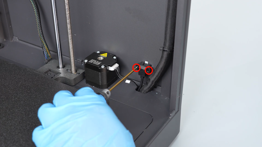
- Loosen the screw securing the camera using a 2.0mm Allen key.
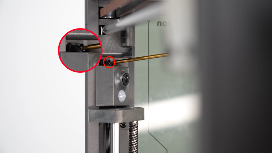
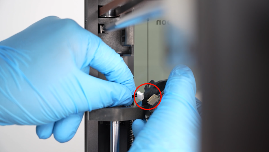
- Unplug the camera cables. Remove the camera.
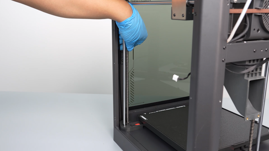
¶ Replace the right-side lead screw
¶ Remove the old lead screw
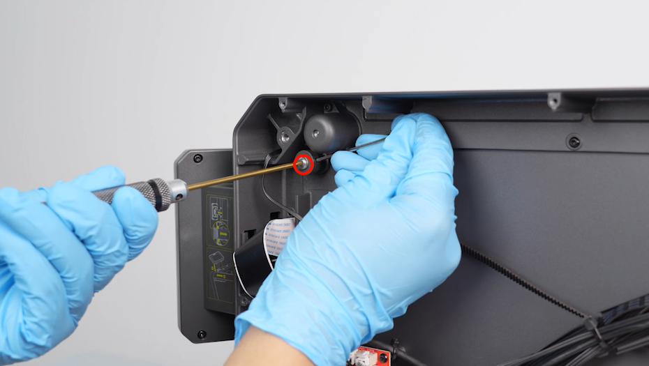
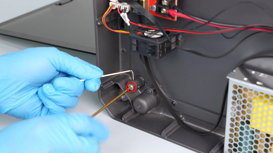
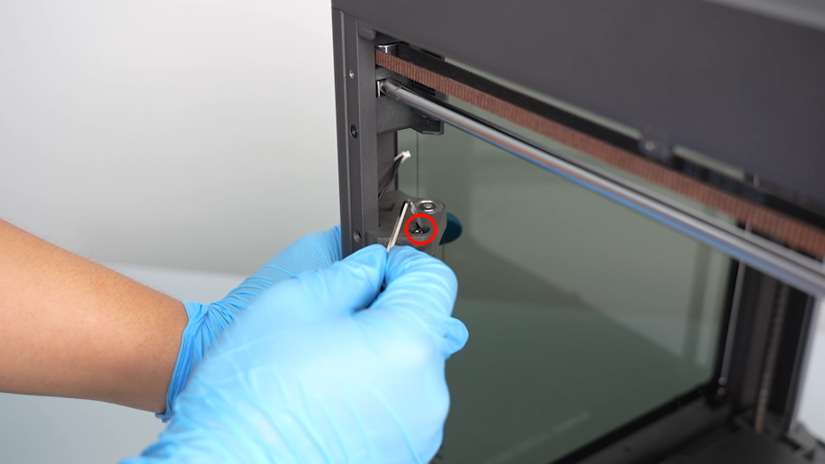
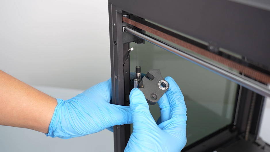
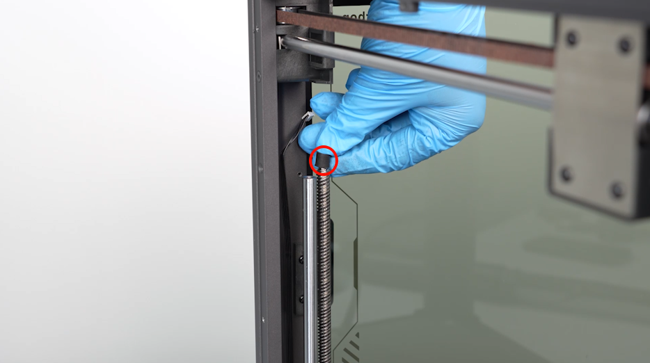
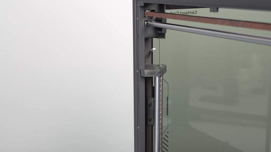
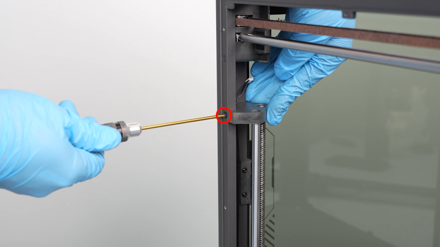
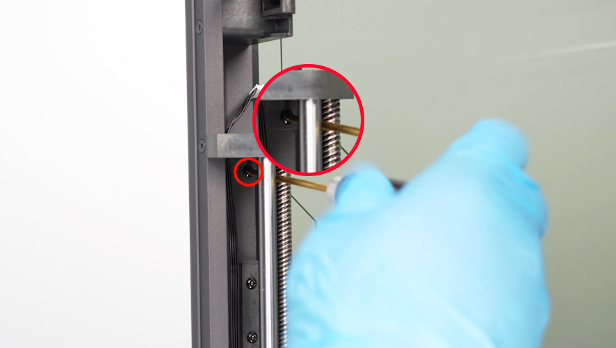
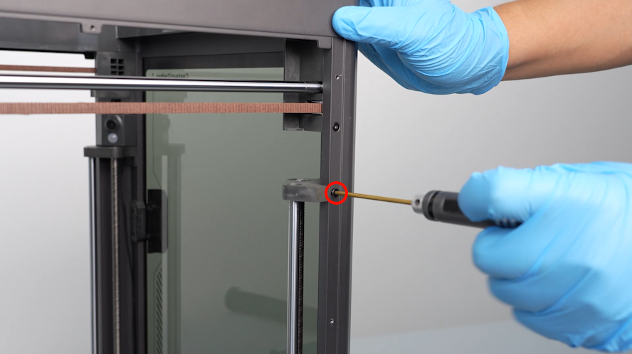
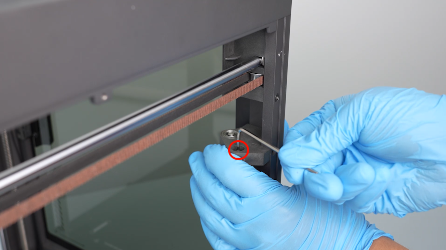
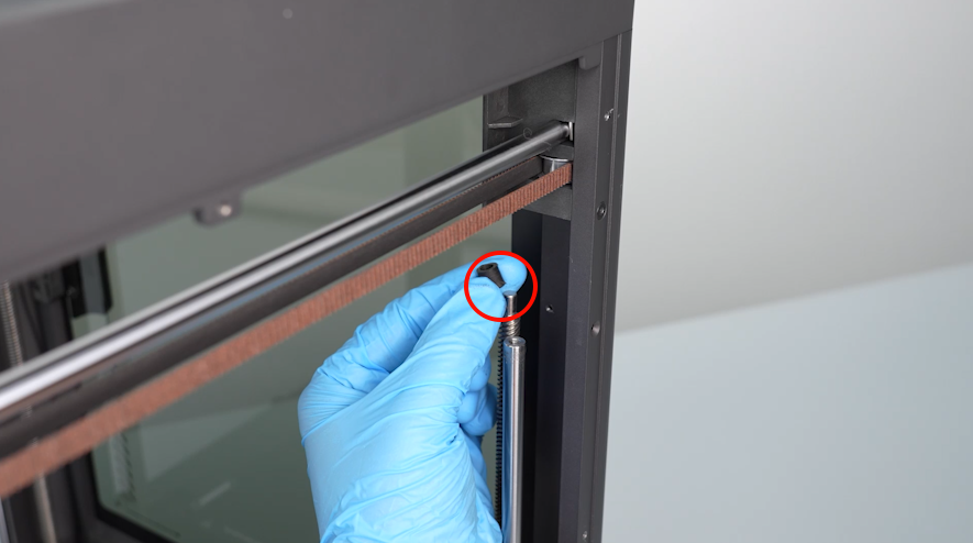
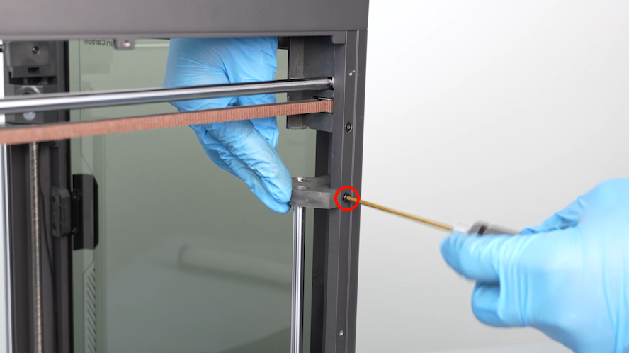
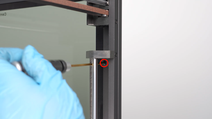
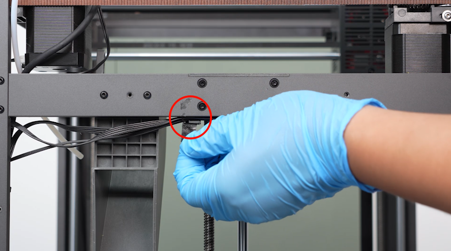
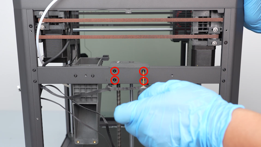
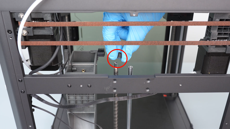
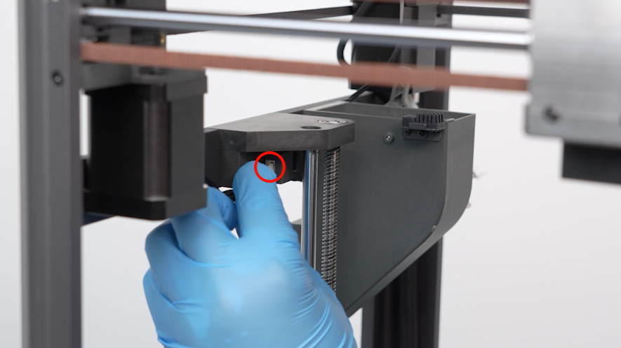
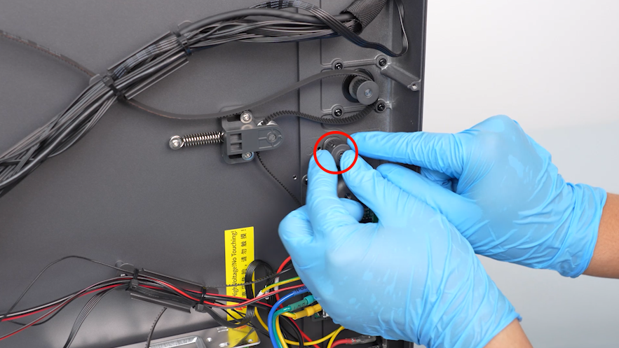
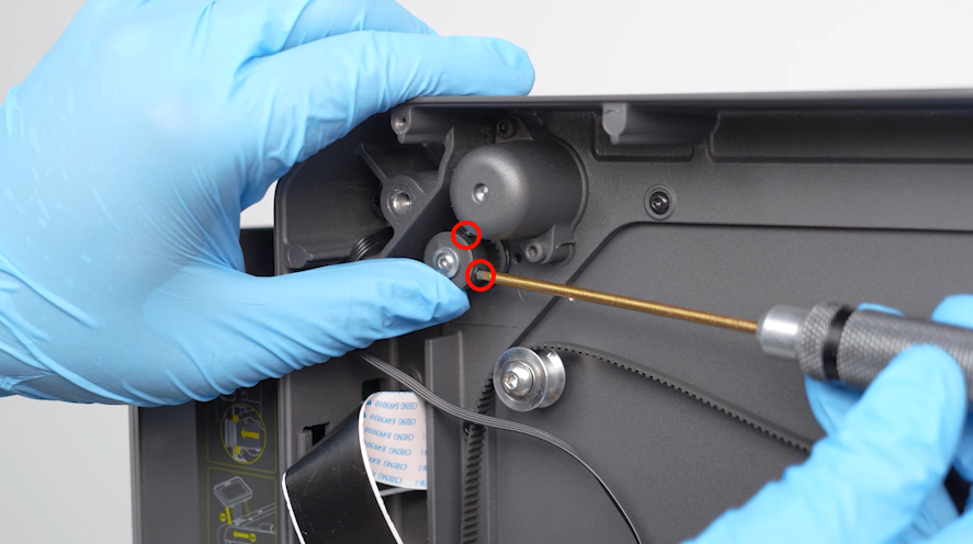
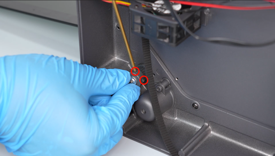
- Using a 2.0mm Allen key, remove the two screws securing the fixing block at the top of the Z-axis.
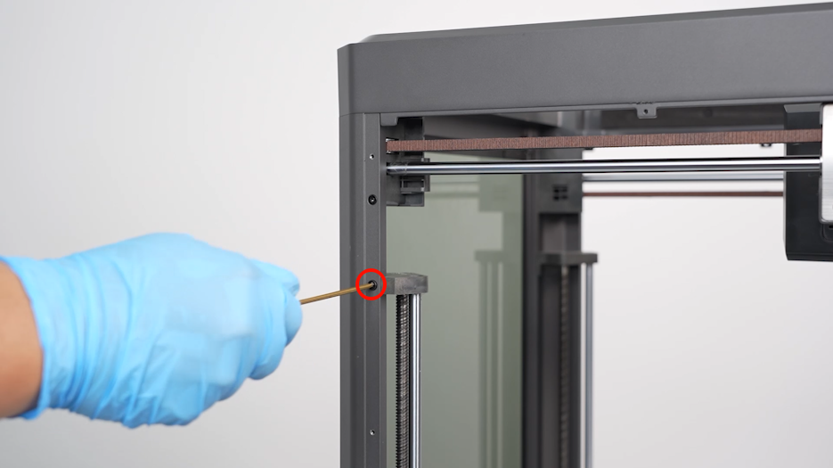
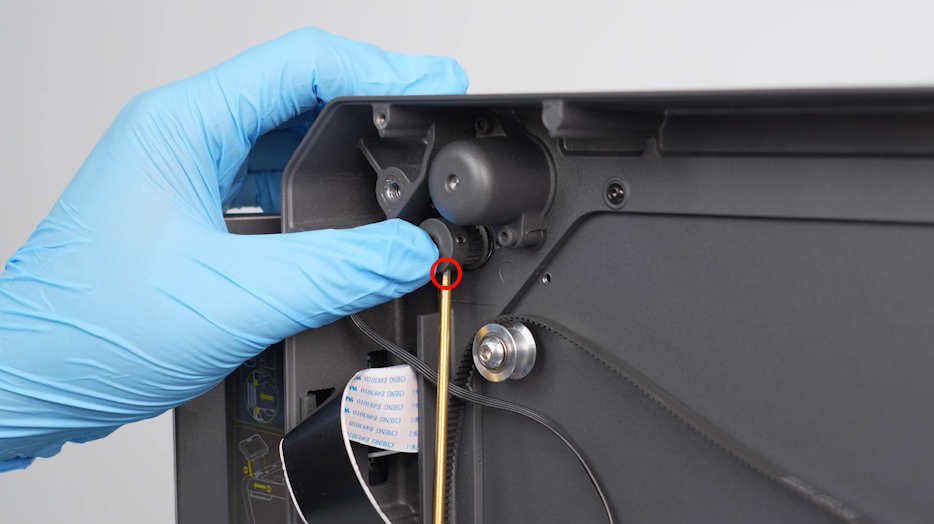
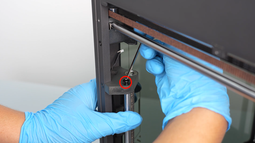
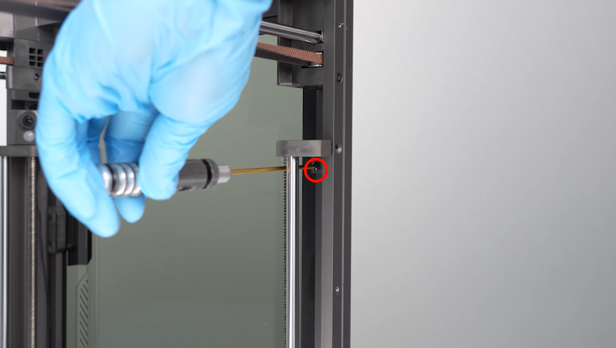
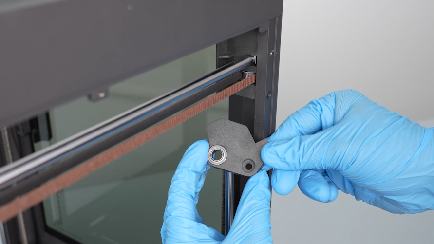
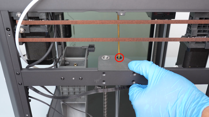
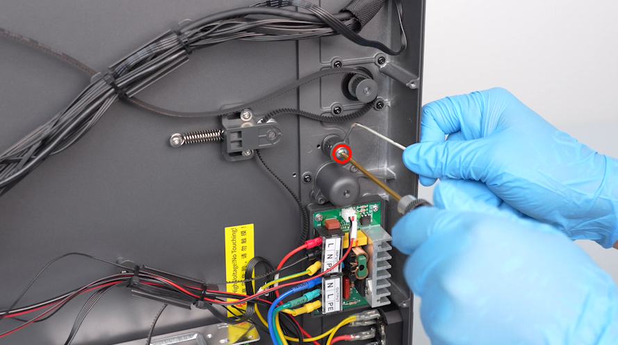
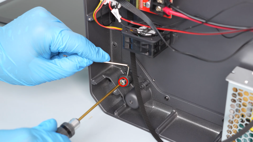
- Using a 2.5mm Allen key, remove the screw secured at the top of the shaft. Remove the fixing block at the at the top of Z-axis and the silicone sleeve.
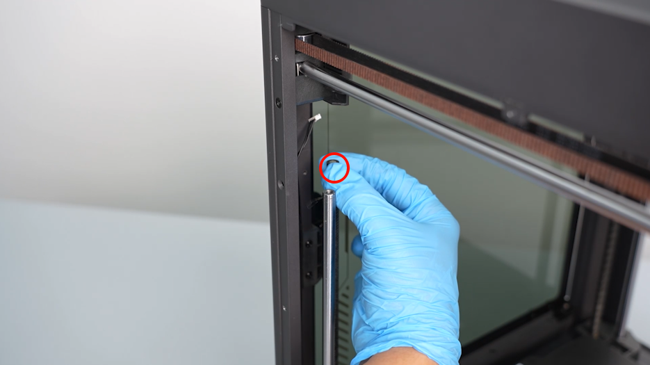
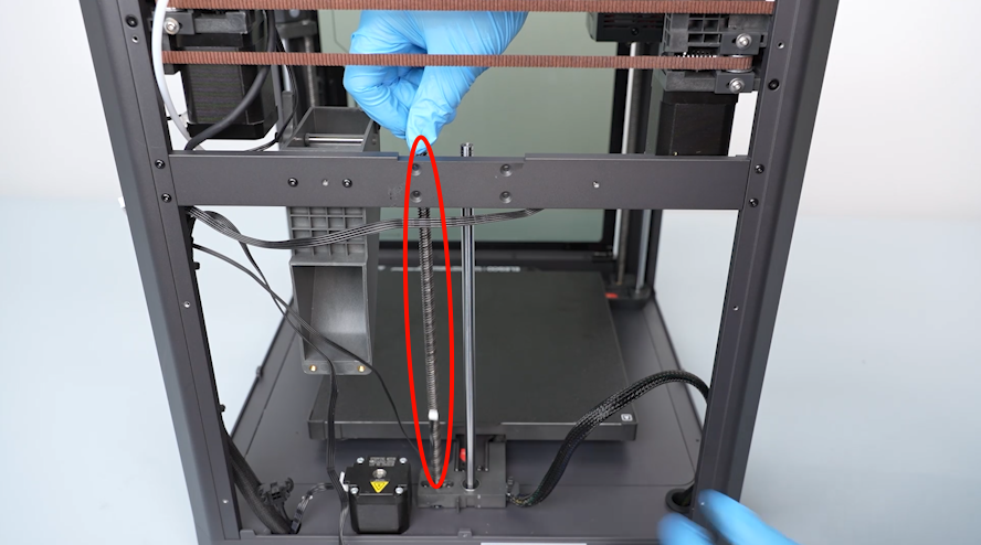
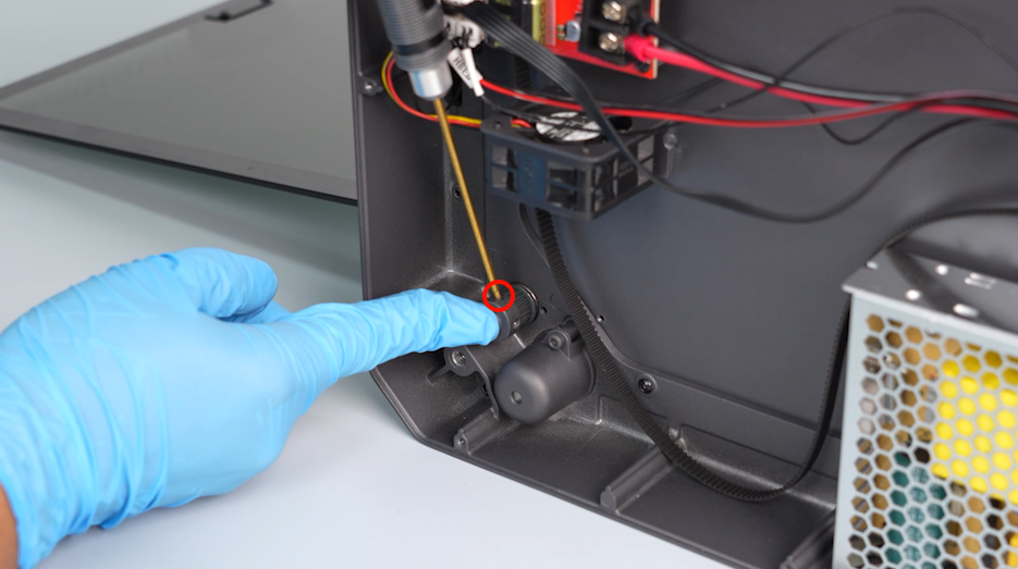
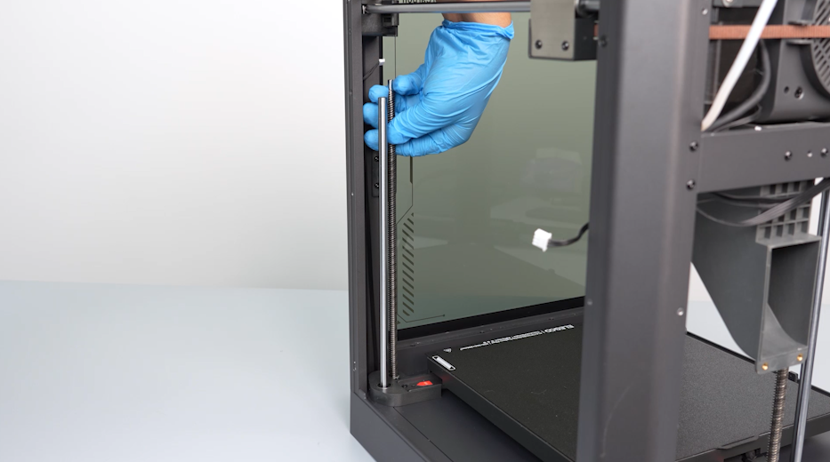
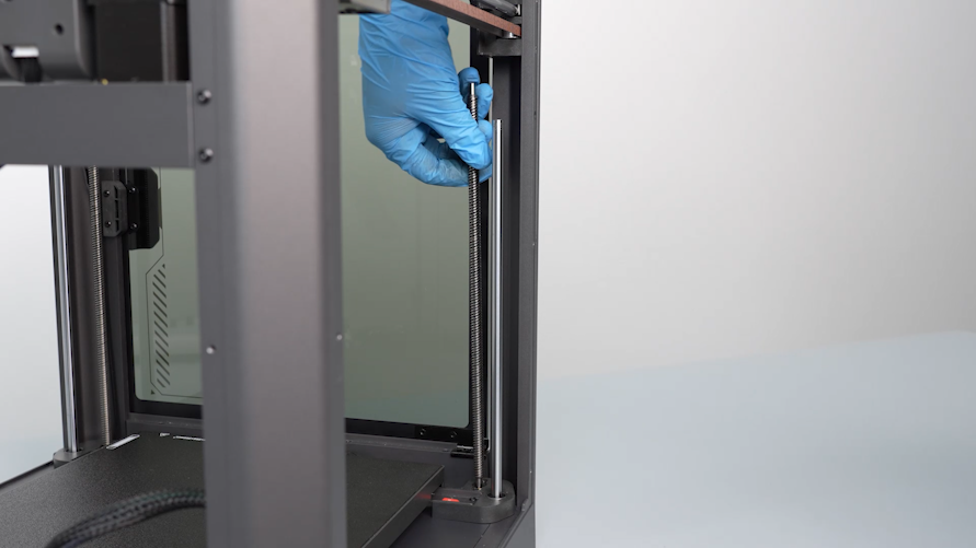
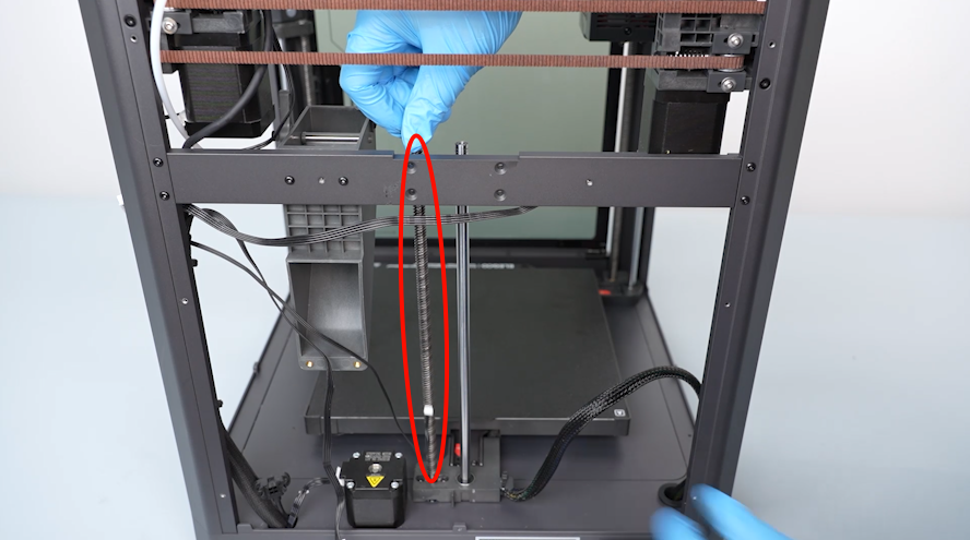
- Rotate and remove the old lead screw.
¶ Install the new lead screw
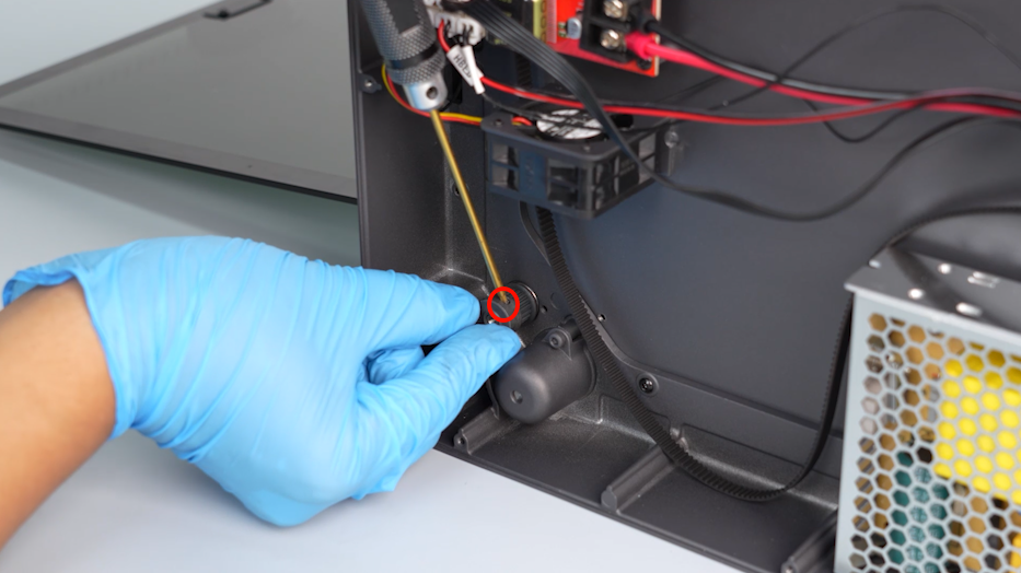
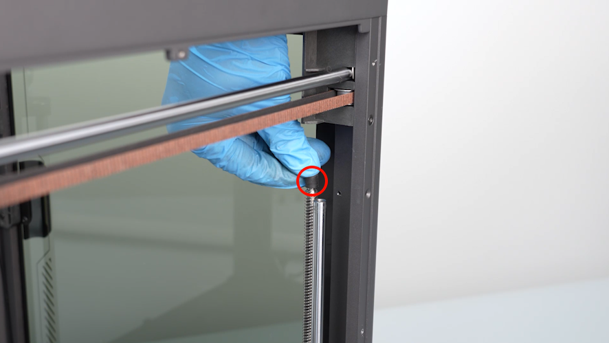
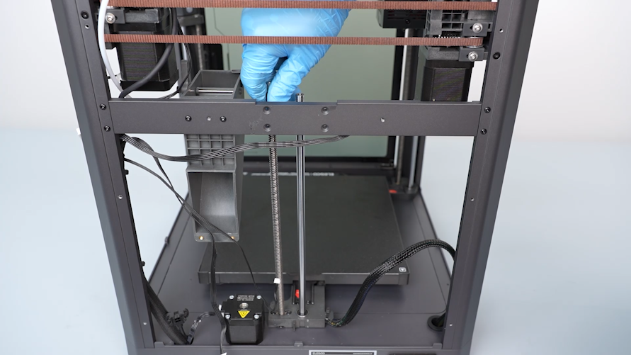
- Prepare the new lead screw. Align it with the installation holes and rotate it until it is in place.
- Put the silicon sleeve in its original position.
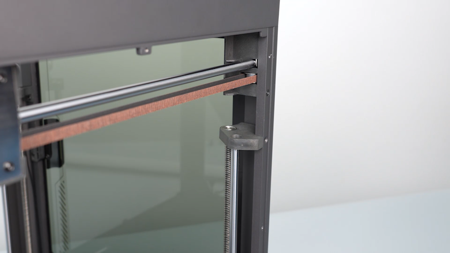
- Align the fixing block at the top of the Z-axis with the lead screw and shaft hole. Put it in the installation position.
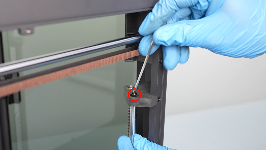
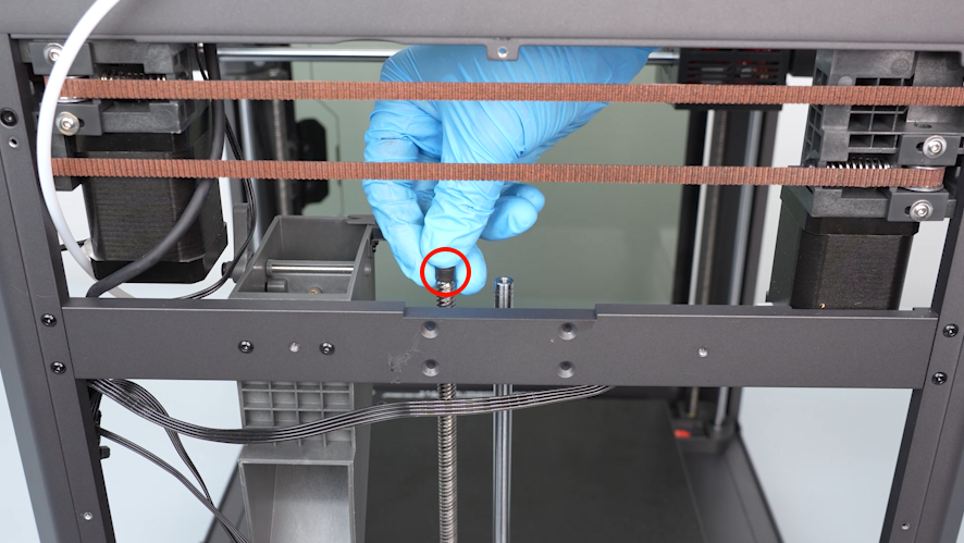
- Using a 2.0mm Allen key, tighten the two screws securing the fixing block at the top of the Z-axis.
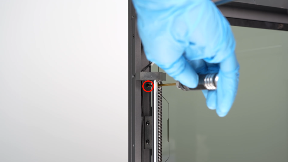
- Using a 2.5mm Allen key, tighten the screw secured at the top of the shaft.
- Prepare the camera assembly. Insert the cables of the camera.
- Tighten the screw securing the camera using a 2.0 mm Allen key.
¶ Replace the left-side lead screw
¶ Remove the old lead screw
- Using a 2.0mm Allen key, loosen the two screws securing the fixing block at the top of the Z-axis.
- Using a 2.5mm Allen key, remove the screw secured at the top of the shaft. Remove the fixing block at the at the top of Z-axis and the silicone sleeve.
- Rotate and remove the old lead screw.

¶ Install the new lead screw
- Prepare the new lead screw. Align it with the installation holes and rotate it until it is in place.
- Put the silicon sleeve in its original position.
- Align the fixing block at the top of the Z-axis with the lead screw and shaft hole. Put it in the installation position.
- Using a 2.0 mm Allen key, tighten the two screws securing the fixing block at the top of the Z-axis.
- Using a 2.5 mm Allen key, tighten the screw secured at the top of the shaft.
¶ Replace the rear-side lead screw
¶ Remove the old lead screw
- Unplug the cables of the rear cooling fan assembly.
- Loosen the three screws securing the rear-side cooling fan assembly using a 2.0mm Allen key. Remove the rear-side cooling fan assembly.
- Unplug the cables of the Z-axis limit switch.
- Peel off the black tape securing the cables and remove the cables from the clip.
- Using a 2.0mm Allen key, loosen the four screws securing the fixing block at the top of the Z-axis.
- Using a 2.5mm Allen key, remove the screw secured at the top of the shaft. Remove the fixing block at the at the top of Z-axis and the silicone sleeve.
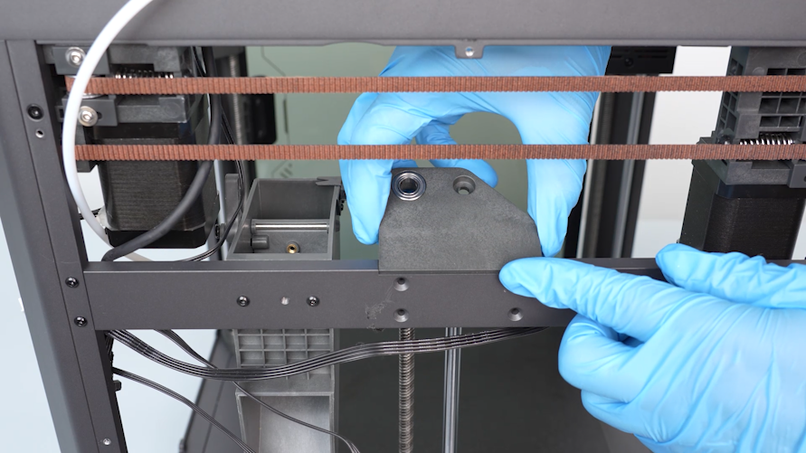
- Rotate and remove the old lead screw.
¶ Install the new lead screw
- Prepare the new lead screw. Align it with the installation holes and rotate it until it is in place.
- Put the silicon sleeve in its original position. Align the fixing block with the lead screw and shaft hole and put it in the installation position. Tighten the screw securing the fixing block at the at the top of Z-axis using a 2.0mm Allen key.
- Using a 2.5mm Allen key, tighten the screw secured at the top of the shaft.
- Organize the cables and put them in the clip. Stick the black tape securing the cables.
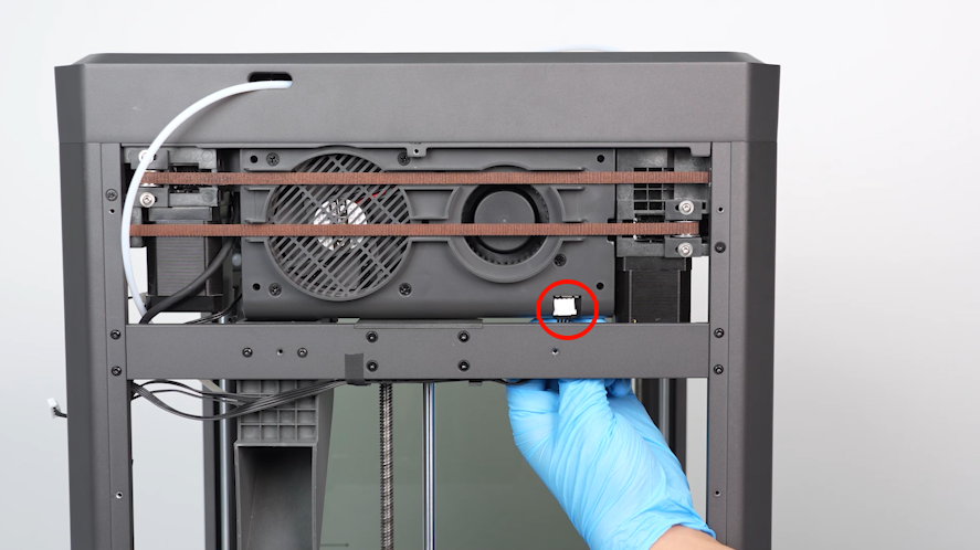
- Insert the cables of the Z-axis limit switch port.
- Align the rear-side cooling fan assembly with the screw holes and put it in the installation position. Tighten the three screws securing the rear-side cooling fan assembly using a 2.0 mm Allen key.
- Insert the cables of the rear cooling fan assembly into the port.
- Align the timing pulley with the lead screw and put it in the installation position.
- Insert a 2.0mm Allen key into the side screw hole to secure the timing pulley. Using another 2.0mm Allen key, tighten the screw at the bottom of the timing pulley.
- Using a 2.0mm Allen key, tighten the two screws securing the side of the timing pulley.
- Install the other two timing pulleys in the same way.
- Organize the timing belt. Install it on the three timing pulleys.
- Using a Phillips screwdriver, tighten the two foot pads at the twos sides of the motherboard.
- Press down on the three points of the heated bed connecting to the lead screw. Keep the three points clinging to the bottom of the printer.
- Press down on the center of the heated bed and keep the three lead screw connection points clinging to the bottom of the printer. Install the timing belt on the idle pulley.
- Use a 2.0mm Allen key to tighten the two screws securing the belt tensioner.
- Put the bottom cover in the installation position by aligning it with the foot pad holes and screw holes. Tighten the ten screws securing the bottom cover using a 2.0mm Allen key.
- Align the left-side cover with the screw holes and tighten the eight screws securing the left-side cover using a 2.0mm Allen key.
- Align the back cover with the screw holes and put it in the installation position. Tighten the twelve screws securing the back cover using a 2.0mm Allen key.
NOTE: Screw holes labeled by the red circle are M3*4, while screw holes labeled by the yellow circle are M3*8.

- Align the multi-color connector with the screw holes and put it in the installation position. Tighten the two screws securing the multi-color connector using a 2.0mm Allen key.
- Put the right-side cover in the installation position by aligning it with the screw holes. Tighten the eight screws securing the right-side cover using a 2.0mm Allen key.
- Pass the cables of the filament runout detection through the hole. Insert the cables into the port.
- Insert the PTFF tube into the connector above the filament runout detection.
¶ Restart the printer
- Plug in the power cord and power on the printer.
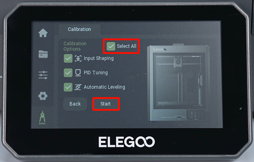
- Select Function - Self check - All - Start on the touchscreen.
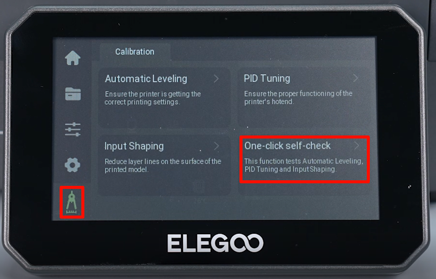
- The printer is ready for use after self inspection.